1
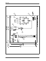
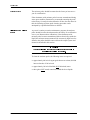
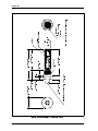
GE Infrastructure
Sensing
Furnace Gas
Sample System
User ’s Manual
GE Infrastructure
Sensing
Furnace Gas
Sample System
User ’s Manual
910-165B1
August 2004
August 2004
Warranty
Each instrument manufactured by GE Infrastructure Sensing is
warranted to be free from defects in material and workmanship. Liability
under this warranty is limited to restoring the instrument to normal
operation or replacing the instrument, at the sole discretion of GE
Infrastructure Sensing. Fuses and batteries are specifically excluded
from any liability. This warranty is effective from the date of delivery to
the original purchaser. If GE Infrastructure Sensing determines that the
equipment was defective, the warranty period is:
•
one year for general electronic failures of the instrument
•
one year for mechanical failures of the sensor
If GE Infrastructure Sensing determines that the equipment was damaged
by misuse, improper installation, the use of unauthorized replacement
parts, or operating conditions outside the guidelines specified by GE
Infrastructure Sensing, the repairs are not covered under this warranty.
The warranties set forth herein are exclusive and are in lieu of
all other warranties whether statutory, express or implied
(including warranties or merchantability and fitness for a
particular purpose, and warranties arising from course of
dealing or usage or trade).
Return Policy
If a GE Infrastructure Sensing instrument malfunctions within the
warranty period, the following procedure must be completed:
1. Notify GE Infrastructure Sensing, giving full details of the problem,
and provide the model number and serial number of the instrument. If
the nature of the problem indicates the need for factory service, GE
Infrastructure Sensing will issue a RETURN AUTHORIZATION
number (RA), and shipping instructions for the return of the
instrument to a service center will be provided.
2. If GE Infrastructure Sensing instructs you to send your instrument to
a service center, it must be shipped prepaid to the authorized repair
station indicated in the shipping instructions.
3. Upon receipt, GE Infrastructure Sensing will evaluate the instrument
to determine the cause of the malfunction.
Then, one of the following courses of action will then be taken:
•
If the damage is covered under the terms of the warranty, the
instrument will be repaired at no cost to the owner and returned.
•
If GE Infrastructure Sensing determines that the damage is not
covered under the terms of the warranty, or if the warranty has
expired, an estimate for the cost of the repairs at standard rates will be
provided. Upon receipt of the owner’s approval to proceed, the
instrument will be repaired and returned.
iii
August 2004
Table of Contents
Introduction . . . . . . . . . . . . . . . . . . . . . . . . . . . . . . . . . . . . . . . . . . . . . . . . . . . . . . . . . . . . . . . . . . . . . . 1
System Design . . . . . . . . . . . . . . . . . . . . . . . . . . . . . . . . . . . . . . . . . . . . . . . . . . . . . . . . . . . . . . . . . . . . 2
Option. . . . . . . . . . . . . . . . . . . . . . . . . . . . . . . . . . . . . . . . . . . . . . . . . . . . . . . . . . . . . . . . . . . . . . . . . . . 3
Installation . . . . . . . . . . . . . . . . . . . . . . . . . . . . . . . . . . . . . . . . . . . . . . . . . . . . . . . . . . . . . . . . . . . . . . . 3
Operation . . . . . . . . . . . . . . . . . . . . . . . . . . . . . . . . . . . . . . . . . . . . . . . . . . . . . . . . . . . . . . . . . . . . . . . . 6
Startup . . . . . . . . . . . . . . . . . . . . . . . . . . . . . . . . . . . . . . . . . . . . . . . . . . . . . . . . . . . . . . . . . . . . . . . 6
Shutdown . . . . . . . . . . . . . . . . . . . . . . . . . . . . . . . . . . . . . . . . . . . . . . . . . . . . . . . . . . . . . . . . . . . . . 7
Maintenance . . . . . . . . . . . . . . . . . . . . . . . . . . . . . . . . . . . . . . . . . . . . . . . . . . . . . . . . . . . . . . . . . . . . . . 7
Cleaning the Moisture Probe . . . . . . . . . . . . . . . . . . . . . . . . . . . . . . . . . . . . . . . . . . . . . . . . . . . . . . . . . 8
Furnace Gas Sample System
v
August 2004
Introduction
Furnace gas is typically comprised of hydrogen, nitrogen, and/or
other select dry gases at temperatures which exceed 400°C (700°F).
These gases contain significant amounts of metallic particles or
vapors. The maximum allowable temperature of the aluminum oxide
probe is 70°C (158°F); therefore, a sample gas stream must be
removed from the furnace and cooled before a moisture measurement
can be taken.
During such cooling, metal vapors sublime to form submicron-sized
metallic particles. Without proper filtration, these particles can
deposit in the aluminum oxide layer of the moisture probe. Metallic
deposition will cause a permanent change in calibration and, if
allowed to continue, will result in permanent damage to the moisture
probe.
The oil bath filter is an effective method of removing submicron,
solid, metallic particles from a gas stream. As the gas bubbles travel
upward through the oil, solid particles are attracted to the liquid
surface and become permanently trapped at the liquid-vapor
interface. The end result is a clean gas exiting the top of the oil bath
filter. When equilibrium conditions exist, the oil will neither remove
nor add water to the sample gas. Therefore, the oil bath filter will not
affect the moisture measurement.
SAMPLE
INLET
NEEDLE
VALVE
FILTER
SAMPLE
CELL
OIL
BATH
FILTER
NEEDLE
VALVE
SAMPLE
OUTLET
SAMPLE
PUMP
Figure 1: Flow Diagram (#732-962FD)
Furnace Gas Sample System
1
August 2004
System Design
Since the gas pressure in most furnaces is low (less than 1/2 psig), the
sample must be drawn through the sample system by a vacuum pump.
The standard Furnace Gas Sample System is illustrated in Figure 3 on
page 4. Your sample system may be slightly different depending on
the options that were ordered. The gases are drawn into the sample
system through the inlet needle valve (Sample Inlet), into the
polyethylene oil bath filter (item 2). The gas will then pass through a
7 micron, sintered, stainless steel filter (item 3) before reaching the
sample cell (item 4), which houses the moisture probe. The gas flows
through the sample cell and the outlet needle valve to the vacuum
pump (item 5) before exiting the sample system.
The standard Furnace Gas Sample System has two filters; an oil bath
filter (item 2) and a 7 micron, sintered, stainless steel filter (item 3).
The function of the oil bath filter is to remove all solid particles from
the gas. See Figure 2 below for a detailed drawing of the polyethylene
oil bath filter. The gas is drawn to the bottom of the filter column
through Tygon tubing, and then bubbled through a saturator stone.
The gas bubbles rise through the oil and exit out the top of the filter
column. This filter is designed for low pressure (less than 25 psig)
and wet dew points (greater than -40°C). The 7-micron, sintered,
stainless steel filter will trap oil droplets escaping from the oil bath
filter, allowing only the gas to reach the moisture sensor.
Union
1/4" SS Tubing
Male Compression Fitting
(bore through)
Sample Inlet
Sample Outlet
Male Compression Fitting
Threaded Aluminum Cap
6061-T6
Polyethylene
Graduated Cylinder
250 ml
Tygon Tubing
Saturator Stone
Figure 2: Polyethylene Oil Bath Filter (#750-290)
2
Furnace Gas Sample System
August 2004
Option
Installation
The standard oil bath filter is constructed of polyethylene
(PN 080A) and is not suitable for high pressure or for very dry gas. At
moisture levels dryer than -40°C frost point, permeation of ambient
moisture through the polyethylene can cause significant errors in the
moisture measurement. For such dry applications, the stainless steel
oil bath filter (PN 080B) is recommended.
1.
2.
3.
4.
5.
Using the mounting holes provided, secure the sample system
mounting plate (item 6) in a weather-protected location as close to
the sample point as possible, preferably within 5 to 10 feet.
Connect the sample port on the furnace to the sample system inlet
valve (Sample Inlet) with 1/4” stainless steel tubing.
Prior to start up, leak test all fittings.
Wire the pump terminal block (item 7) to a 115 VAC power
source (see Figure 3 on page 4). We recommend using a power
cord that is wired to an on/off switch.
Fill the oil bath filter (item 2) with approximately 120 ml of oil
(just less than half full). Use a detergent grade 10W40 motor oil,
preferably one that is produced in Texas, which you would use in
your automobile engine. (It has been found that oils produced
outside Texas contain additives that may adversely affect the
aluminum oxide moisture sensor.) Save the remaining 7/8 quart,
and change the oil every month or as required.
Note:
6.
7.
Furnace Gas Sample System
The polyethylene oil bath filter is shipped without oil.
Thread the moisture probe into the sample cell (item 4) and tighten
1/8 of a turn past finger tight.
Snap the connector end of the probe cable onto the moisture probe
and wire the other end of the cable to the hygrometer read-out
unit. Refer to the hygrometer user’s manual for wiring
instructions.
3
August 2004
6
AI
D
"2
/1
7
PY
T)
7.
21
(
5
DNU OR G
L A RT UE N
EL
P
M
A
S
E NI L
TE
LT
U
O
4
)8
.1
34
(
00
.7
1
)4
.7
83
(
52
.5
1
EL
P
M
A
S
).s
re
te
im
li
(m
se
hc
ni
in
er
sna
ois
ne
m
iD
LL
E
C
1
3
NUPRO
1
2
EL
P TE
ML
I
SA N
)2
.2
2(
57
.8
00
.7
1
)8
.1
34
(
5
.25
1
)2
.2
2(
57
.8
)4
.7
83
(
Figure 3: Mounting and Assembly Drawing (#732-962AS)
4
Furnace Gas Sample System
EL
ITT
Furnace Gas Sample System
Mounting Plate
175
TS
6
7
Terminal Strip
Sample Pump
173A
5
3-Pin Terminal Strip for Pump Wiring
17" X 17" White Enamel Painted Steel
30 SCFH (max), 115 VAC
5000 psig, 316 SS
Sample Cell
2830
4
1
1
1
1
1
6000 psig, 7 micron Sintered SS Element,
316 SS, Tee-Type
Particulate Filter
075
3
1
1
E
M
A
N
25 psig, Polyethylene
N
O
IT
PI
R
C
SE
D
Oil Bath Filter
080A
M
ET
I
2
M
B
2
732-962
.Y
T
Q
5000 psig, 316 SS
Needle Valve
.
O
N
LE
D
O
M
.
O
N
TR
A
P
035
Furnace Gas Sample System Bill of Materials
VE
R
1
SS04B-0-0-0
August 2004
Figure 4: Bill of Materials (#732-962BM)
5
August 2004
Operation
Start Up
To operate the Furnace Gas Sample System, refer to Figures 2 and 3
on pages 4 and 5, and complete the following steps.
To start up the system:
1.
2.
3.
4.
5.
6.
Check the moisture probe calibration date at the top of the
supplied calibration data sheet. It is recommended that probes
with calibration dates older than one year be returned to
Panametrics for recalibration.
Verify that the calibration data for the moisture probe is
programmed correctly into the hygrometer. Refer to the
hygrometer user’s manual for wiring instructions.
Close both needle valves.
Open the inlet needle valve (Sample Inlet).
Turn on the sample pump (item 5).
Slowly open the outlet needle valve which is located between the
sample cell (item 4) and the vacuum pump (item 5).
Caution!
Be careful not to open the outlet valve too quickly, as oil
from the filter could flood the sample system.
The sample pump can pull a maximum of 30 SCFH of gas through
the sample system. However, it is recommended that the flowrate be
adjusted so that the oil bubbles to approximately 3/4 of the height of
the oil filter column (item 2). (If a flowmeter is mounted on the
sample system, set the flowrate to mid-scale.) The sample gas can be
vented to any atmospheric pressure location of your choosing.
The hygrometer will continuously monitor the moisture content of the
furnace gas. Before accepting the hygrometer reading as
representative of moisture in the furnace, be sure the system has
reached equilibrium . To determine when equilibrium has been
reached, record the dew/frost point readings at 5 minute intervals.
Equilibrium can be confirmed when the same dew/frost point
readings (±0.5°C) have been recorded in three consecutive
measurements.
6
Furnace Gas Sample System
August 2004
Shut Down
To shut down the system:
1.
Maintenance
7-micron Filter
Close the outlet valve which is located between the sample cell
(item 4) and the sample pump (item 5).
2.
Turn off the sample pump (item 5).
3.
Close the inlet valve (Sample Inlet).
4.
Disconnect the moisture probe cable from the moisture probe.
5.
Remove the moisture probe from the sample cell (item 4).
Periodically, the sample system should be inspected and tested to
insure a satisfactory installation. Panametrics recommends the
following items be checked:
During a sample system shutdown, the 7-micron filter in the tee-type
filter housing should be removed and inspected.
1.
Remove the filter by unthreading the lower cylindrical portion of
the housing.
2.
Inspect the filter for particulates or contamination.
3.
Clean or replace the filter element as needed.
Note:
4.
5.
Oil Bath Filter
Install the new filter element in the cylindrical housing, with the
open portion of the element facing upward.
Thread the cylinder onto the tee-type housing.
The filter oil should be changed every month, or as required, to
ensure proper operation.
1.
2.
3.
4.
5.
Furnace Gas Sample System
Panametrics offers replacement filter elements (P/N 076) for
this housing. Contact the factory for additional information.
Remove the lower portion of the oil bath filter.
Inspect the saturator stone for particulates and clean as necessary.
The stone can be cleaned by blowing compressed air through it to
remove any accumulated particulates.
Drain the used oil into a proper disposal container.
Refill the filter with new (unused) oil according to the installation
instructions on page 3.
Thread the cylinder onto the housing.
7
August 2004
Moisture Probe
The moisture probe should be returned to the factory at least once a
year for recalibration.
If the aluminum oxide moisture probe becomes contaminated during
some upset condition, Panametrics recommends returning the probe
to the factory for analysis and recalibration. If time does not allow for
this, the following moisture probe cleaning procedure can be
attempted by a qualified technician or chemist.
Cleaning the Moisture
Probe
As part of a routine preventive maintenance program, the moisture
probe should be removed and returned to the factory for recalibration
once a year. Between these calibrations, if the aluminum oxide
moisture probe becomes contaminated with an electrically conductive
liquid, the moisture measurements will be erroneously high. In such a
situation, the probe should be removed from the sample system and
cleaned as described in this section.
!WARNING!
The probe cleaning procedure should be performed only by
a qualified technician or chemist.
To clean the moisture probe, the following items are required:
8
•
approximately 600 ml of reagent grade hexane or toluene, divided
into two batches of 300 ml each
•
approximately 300 ml of distilled (NOT deionized) water
•
three glass (NOT metal) containers to hold the above liquids.
Furnace Gas Sample System
August 2004
Cleaning the Moisture
Probe (cont .)
To clean the aluminum oxide moisture probe, complete the following
steps:
1. Record the dew point of the ambient air.
IMPORTANT: To avoid damaging the sensor during the following
steps, do not allow the sensor to contact the walls or
the bottom of the containers.
2.
3.
4.
5.
6.
7.
8.
9.
Carefully remove the protective shield covering the sensor without
touching the exposed sensor (see Figure 5 on page 10).
Soak the sensor in one of the containers of hexane or toluene for
10 minutes.
Remove the sensor from the hexane or toluene and soak it in the
container of distilled water for 10 minutes.
Remove the sensor from the distilled water and soak it in the
second container of (clean) hexane or toluene for 10 minutes.
Remove the sensor from the hexane or toluene and place it sensorside-up in an oven set at 50°C ± 2°C (122°F ± 3.6°F) for 24 hours.
Repeat Steps 3-6 to clean the protective shield. To ensure the
removal of any contaminants that may have become embedded in
the porous walls of the shield, swirl the shield in the solvents
during the soaking procedure.
Without touching the exposed sensor, carefully reinstall the
protective shield over the sensor.
Connect the probe cable to the cleaned probe and measure the dew
point of the same ambient air recorded in Step 1.
10. If the probe is determined to be in proper calibration (±2°C/
±3.6°F), it has been successfully cleaned and may be reinstalled
in the sample cell.
If the probe is not in proper calibration, proceed to Step 11.
11. Repeat Steps 1-10 using soaking time intervals of 5 times the
previous cleaning sequence, until two consecutive cleanings
produce identical probe responses to the ambient dew point.
Furnace Gas Sample System
9
August 2004
dl
ei
hS
R
ro
sn
eS
)5
.90
8(
78
1.
3
)8
.58
2(
52
1.
1
)5
1.
75
(
520
.2
)0
.83
2(
73
9.
0
)y
tis
roo
P
no
rci
M
00
(1
)5
7.
(4
78
1.
0
)5
3.
6(
05
2.
0
eiz
S
gn
iR
-O
88)
.5
(1
52
6.
0
DH
T
61
-4
/3
.
iDa
23
/3
x
DI
4/
3
).
res
te
im
li
(m
se
hc
ni
in
er
as
no
is
ne
m
iD
A)
no
itV
(
)5
.89
6(
05
7.
2
)0
1.
11
(
73
4
0.
P4
-8
-H
1T
#.P
nn
oC
xi
dn
eB
ot
tn
lea
ivu
qE
Figure 5: Panametrics M2 Moisture Probe
10
Furnace Gas Sample System
USA
221 Crescent St., Suite 1
Waltham, MA 02453-3497
Telephone: 781-899-2719
Toll-free: 800-833-9438
Fax: 781-894-8582
E-mail: [email protected]
Web: www.gesensing.com
Ireland
Shannon Industrial Estate
Shannon, County Clare
Ireland
Telephone: 353-61-470200
Fax: 353-61-471359
E-mail: [email protected]