1
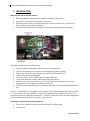
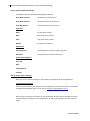
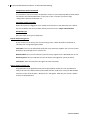
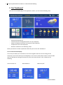
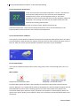
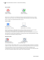
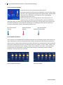
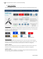
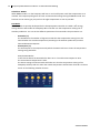
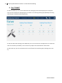
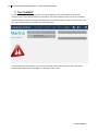
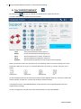
1 Heatpump WiFi Module Installatie- en Gebruikershandleiding
Heatpump WiFi Controller
For swimming pool heatpumps
Installation- and user manual
201405140850.1
2 Heatpump WiFi Module Installatie- en Gebruikershandleiding
1. INSTALLATION
Mounting the Heat Pump WiFi module
1. Before installing het Heatpump WiFi module , energize the Heatpump.
2. Unscrew the cover from the Heatpump en remove it.
3. Plug the power cord of your Heat Pump WiFi module connector A on the print of
your pool heat pump (see illustration)
4. Screw Heat Pump WiFi module then in the location specified (see illustration)
Installing the application on iOS devices
1.
2.
3.
4.
5.
6.
7.
Take your tablet or smartphone with iOS and open the App store
Touch at the bottom of the screen on the magnifying glass (search)
Type in the search bar the search term "Heat Pump Controller WiFi"
The search results are displayed
Touch the "Free" in the "Heat Pump Controller WiFi"Klik
Touch here after the "Install" button which will then appear
After this you may need to log in to the iTunes Store, this depends on your own
settings on your smartphone or tablet PC with iOS
8. The Heat Pump Heat Pump WiFi Controller application is now installed and ready for
use.
Caution ! The application is available in two variants; an iOS smartphones and iOS for tablet
pc. If you want to use the application on both a smartphone and a tablet PC with iOS, you
must perform above steps on both devices. To use the Heat Pump WiFi controller application
you should at least have iOS 7.0 or later on your device.
Installing the application on Android-tablet pc’s
1. Find on your tablet PC with Android the Google Play Store app
2. Touch search
201405140850.1
3 Heatpump WiFi Module Installatie- en Gebruikershandleiding
3.
4.
5.
6.
7.
Search for “Heat Pump WiFi Tablet”
The app “Heat Pump WiFi Tablet Heat Pump Controller” will appear
Touch the button “Install”
Read the rights which the application gets and touch “Accept”
The Heat Pump WiFi Tablet Heat Pump Controller application is now ïnstalled on your tablet
pc with Android and ready for use.
Caution! The application is available in two variants for Android: one for tablet pc’s and one for
smartphones with the Android operating system. Note
that you actually "Heat Pump Controller WiFi Tablet" install on your tablet. To install and use
the application your Android Tablet PC must at least have Android 4:03 or later.
Connecting the heatpump WiFi module with a wireless network
To connect the WiFi module to the internet you’ll use an existing networkconnection. Make sure
there is a sufficient reach between the wireless network and the place you put your heatpump
Check if there is an available network connection on the place of the heatpump by trying to connect
to google.com on your smartphone or tablet. If there is no available wireless network, you first have
to connect a proper wireless network at the place of the heatpump. Herefore you can use WiFi
extenders or repeaters. For this we refer you to the ppoint of purchase from your network
To install the heatpump WiFi module, you’ll need the following data:
-
Networkname (SSID)
Network key (password)
The heatpump Wifi module uses the revolutionary BlinkUp technology. This technology allows you to
install your heatpump WiFi module with your wireless network by flashes of light. This is a simple
task through the following steps:
1. Open the BlinkUp application (easy to install from Google Play store, Apple app store,
Windows Phone Marketplace)
2. Make sure your heatpump (and the WiFi module) is provided with electricity
3. The LED of t the heatpump WiFi module will blink red (if this is not the case, you have to
make the device without electricity and with electricity again).
4. Choose your wireless network in the Blink application
5. Give the network key (password) of your wireless network in the Blink application
6. Tapp ‘’Sens BlinkUp’’
7. Keep the screen of your Smartphone/tablet as close as possible against the sensorside of the
heatpump WiFi module during the whole time the screens blinks (make sure your phone and
heatpump WiFi module ar as stationary as possible
8. It will take around 10 to 20 seconds to make a succesfull installation
9. When the connection is succesfully made the built-in LED will blink green, your heatpump
WiFi module is now connect through the internet
201405140850.1
4 Heatpump WiFi Module Installatie- en Gebruikershandleiding
Caution: You will be advised to set up the network through an Apple Iphone. In connection with the
hardware that is being yo uit could occur that the BlinkUp technology isn’t working properly in
combinayion with your other devices. This only applies to the set up of the network data in your
heatpump WiFi module and has no consequenses for the furtheruse of the application and the
module
When you don’t have an Apple Iphone for the BlinkUp technology to configure the heatpump WiFi
controller, you can also use an Android phone. Because there are many different Android
smartphones, it is not always possible to succesfully configurate through an Android smartphone. To
get the best result possible, you should make sure you have the following setting on your Android
smartphone to sent the BlinkUp settings:
-
Make sure the brightness of your screen is not on ‘’automatic’’
Make sure the brightness of your screen is on ‘’max’’
Make sure that the power saving mode is of with a Samsung smartphone
o Swipe from top to bottom on your home screen will open Quick Settings menu
o Scroll though your menu to ‘’Power Saving’’
o Swith the power saving mode ‘’off’’
2. Installation of the app at first use
When you use the Heatpump WiFi controller for the first time you have to configure your
smartphone or tablet. Herefore you can use the following instructions on your smartphone or tablet
screen.
Step 1: Start the application on your smartphone or tablet by tapping on the Heatpump WiFi
controller icon.
Step 2: Tap on ‘’Setup’’ to start ‘’settings at first use’’. Following the instructions on your screen. Tap
‘’next’’
Step 3: Setup: Administration:
This is the screen where you have to set up your personal settings, as well as the serial
number of your heatpump and of the heatpumpm WiFi module. Beside you have to give the
contact of your installer. The serial number of the heatpump is used to be found at the white
sticker on the side of your heatpump (usually underneath the nameplate with technical
aspects). The location of the sticker can differ bye ach model. The serial number of the
heatpump WiFi module can be found at the module (built in at step one) itself.
The in given data will only connect your heatpump with a cloud server to make sure the
relevant data will be send to your e-mail. This data will never be used for other (commercial)
purposes and will never be released to third parties.
201405140850.1
5 Heatpump WiFi Module Installatie- en Gebruikershandleiding
Step 4: Setup: Pool/Pond Settings:
Through this step you will set the following parameters
Pool Water Volume:
the pool water volume in m³
Pool Water Surface:
the water surface of the pool m²
Pool Wall Surface:
the wall surface of the pool in m²
Poolcover:
None
no poolcover present
Basic
basic pool cover present
Solar
solar pool cover present
Blanker
foil pool cover present
Application:
Swimming Pool
The heatpump is used for a swimming pool
Fish Pond
the heat pump is used for a fish pond
Construction Material:
Concrete
Brick
Isolation Brick
Insupool
Stap 5: Setup: System Settings
Here you can set various settings for the purpose of the operation of the application
Location data heatpump
At first you have to fill in the location of your heatpump on the basis of location coordinates
(Latitude and Longitude) that you can find on http://nl.mygeoposition.com/
Here you have to set up the location of your heatpump. By this it will be possible to see the
current wheater conditions on your application, as well as the possibilty to switch to ECO
mode
201405140850.1
6 Heatpump WiFi Module Installatie- en Gebruikershandleiding
Temperature Sensor Connected
It is possible to connect an extern temperature sensor on your Heatpump WiFi module which
can measure the watertemperature in your pool. If this is connect you have to flag:
“Temperature Sensore Connected” on.
Send alarm email to installer
When this function is flagged on your installer will receive an e-mail when there is a failure.
This e-mail will be sent to the installer which you have set up in step 3 administration
Heatpump type
Here you select your type of Heatpump.
Stap 6: Setup: Energy Cost
In this screen you can set up your current energy costst. These data will be used later to
calculate your savings during ECO mode
Tariff Plan: here you can indicatethe tariff plan your electricity supplies uses. You can choose
between a day and night rate or a fixed rate.
Weekend Plan: here you can indicate if your electricity supplier uses a Weekend plan or not.
Electricity Price: here you indicate the rates of the day and nightrate (cents per KwH)
Tariff Zones: these are the times the night rate starts and stops
Stap 7: Setup: Finishing up…
Congratulations! The application and your heatpump WiFi module are now installed and
ready to be used. The data will be synchronized with the cloud server and your WiFi module.
Leave this screen until the tekst: ‘’Ready To Go’’ will appear. After this you can tap ‘’START’’
to move to the dashboard
201405140850.1
7 Heatpump WiFi Module Installatie- en Gebruikershandleiding
3. Tab “Dashboard”
This tab is the standard page of the application, where you can see the following data:
-
Current time and settings timer-function
Actual pool temperature
Location and surroundingstemperature of your heatpump
Power of the WiFi connection on the place of the heatpump
Temperature set for the heatpump
Wheater conditions in the following 5 days
Below you will find a further explanation about the parts of the tab ‘’dashboard’’
Part 1: Time and statusdisplay
This is the part where you can find the current time together with the current settings of the
heatpump. You will see directly if the heatpump is set to Timer-mode, Boost-mode or manual mode.
Also you will find the settings of the timer if you use the timer function. This is shown by the
following
Timer-function on
Boost Mode on
Manual on/off
201405140850.1
8 Heatpump WiFi Module Installatie- en Gebruikershandleiding
201405140850.1
9 Heatpump WiFi Module Installatie- en Gebruikershandleiding
Part 2: Actual water temperature
In this second part the actual pool temperature is shown. This value can
be measured in different ways. This value will show standard the
temperature the sensor at the heatpump measures. This sensor
calculates the value of the water that flows into the heatpump. When the
heatpump is not working, the value that was measured last when the
heapump was working will be shown.
This value can also be measured by an external sensor, which will measure the
poolwatertemperature.. These external temperaturesensors can be connected directly to the
heatpump WiFi module to measure the accurate pool temperature.
Part 3: Actual wheater conditions
In this part the actual wheater conditions of the place the heatpump stands will be shown. The place
of the heatpump is determined by the settings of the geo-data you have entered during the set-up at
firat use. Here you see the accurate wheater conditions at the place of your heatpump.
Part 4: Status-display
In this part the different statuses will be shown using various icons. The meaning of the icons is as
follow:
WiFi-symbols:
Heatpump not connected to WiFi
Heatpump is connected to WiFi
The above Wifi symbols will show if the heatpump is connected to the wireless network and the
internet. When the right symbol will be shown the heatpump can’t be controlled by distance and and
the heatpump first have to have a working signal. At the most right symbol the strength of the
connection will be sjown. More the stripes, the better the connection at the heatpump. When the
signal is from poorer quality, there could be a delay in the connection and akso problems with loss of
connection.
201405140850.1
10 Heatpump WiFi Module Installatie- en Gebruikershandleiding
Alarm-symbols
Alarm-symbol A
(There is a failure)
Alarm-symbol B
(There is no failure)
When there is a failure with your heatpumo the Alarm-symbol A will be shown in part 4: statusdisplay. On the tab ‘’alarms’’ you can find the possible causes and solutions for the failure. When
there is no failure, the symbol B will be shown in part 4
Defrost-symbol
Defrost-symbool A
(defrostmode is working)
Defrost-symbool B
(defrostmode is not working)
When the heatpump is in defrosting mode, the defrost-symbol A wil be shown in part 4: statusdisplay. When the defrostingmode is not working Defrost-symbol B will be shown.
The defrosting of a heatpump is periodically needed to make sure the heatpump will continue the
right operation. During the defrostingmode the heating system will be turned upside down to make
sure that ice on the condensor will be prevented.
Waterflow-symbol
Waterflow-symbol A
(no waterflow detected)
Waterflow-symbol B
(waterflow detected)
Above waterflow symbols display if there is or isn’t a waterflow through the heatpump. If waterflowsymbol A is visible, it means dat there is no water detected through the flow switch in the heatpump.
In this case the flow is to low to use the heatpump, you can solve this by switching on the
circulationpump. Tips to make sure there is enough waterflow can be found in the application under
tab ‘’alarms’’(only when symbol A will be shown). Type in failurecode EE03.
201405140850.1
11 Heatpump WiFi Module Installatie- en Gebruikershandleiding
Part 5: Temperature display
In the fifth part the divers temperatures will be shown.
De big red temperature will show the temperature set (in this case: 28°C).
Also the in and outgoing water temperatures will be shown, which will be
measured at the heatpump. In the image are the in and outgoing
temperatures the same (27°C).
When the heatpump is not working (because the temperature set is
reached or there is a failure), the thermometer in part 5 will be shown
with a grey filling, as shown in the image. When the heatpump is heating, there will be shown a red
animation from bottom to top. When the heatpump is in coolingmode, there will be shown blue
animation from bottom to top. Underneath the divers icons:
Blue thermometer
Cooling
Red thermometer
Heating
Grey thermometer
Heatpump off/standby
Part 6: Wheater prediction
In the sixth part of the dashboard the wheater predictions for the following 5 days will be shown. De
upper temperatures are the predicted maximum outdoor temperatures with above an indication if i
twill be sunny or cloudy. The bottom line of numbers will show the set temperature of the heatpump
fort hat dat. Before this tow there is an indication which says ‘’MAN’’ or ‘’ECO’’. When ‘’MAN’’ is set
the manual set temperature (tab ‘’settings’’) will be shown. When is says ‘’ECO” , the temperature
settings will be set automatically on the basis of ECO-settings in combination with the weather
predictions. Part 6 will be shown as follow:
Part 6: weather prediction with a
Manual temperature (28°C)
Part 6: Wheater condition with a
Active ECO-mode
201405140850.1
12 Heatpump WiFi Module Installatie- en Gebruikershandleiding
4. Tabb “SETTINGS”
In the tab ‘’SETTINGS’’ you can set the most common settings of the heatpump using simple icons.
Operating Mode
Here you can set the heatpump to cooling, heating or automatic mode. Also the temperature can be
set using – or + at right. Below the function buttons is said what the button does. In the example the
heatpump is said to be “Heating 28°C”.
These are the icons and their meaning:
Cooling non-active
Cooling active actief
Automatic non-active Automatic active
Heating non-active
Heating active
Lower temperature
Raise temperature
Operating Schedule
Here the operation schedule of the heatpump can be set. These can be put on and off simply by
pressing on or off. Below a prescription of the different operating schedules is given. Caution: The
heatpump can only work when the filter/circulationpump is on and there is enough flow.
Schedule 1: ON/OFF
When you use this setting you have to put on your heatpumo ON or OFF by manual. Caution: The
heatpump can only work when the filter/circulationpump is on and there is enough flow.
Schedule 2: TIMER
When you have schedule 2 (TIMER) on, the heatpump will go on and off automatically on the times
set. These setting can be set by audit on the tab TIMER
201405140850.1
13 Heatpump WiFi Module Installatie- en Gebruikershandleiding
Schedule 3: BOOST
When BOOST mode is on the heatpump will heat or cool at full power untill the temperature set is
reached. The heatpump will ignore all Timer and ECO mode settings during the BOOST mode. This
function can be used to get your pool on the right temperature as soon as possible.
ECO Mode
The ECO mode is specially developed fot the heatpump WIFI controller to enable a 20% energy
saving. With the ECO mode the heatpump WiFI controller sets the temperature making use of
weather predictions. You can set the different parameters for ECO mode. The parameters are:
-
-
ECO Delta (°C)
The ECO Delta is the number of degrees outside that the temperature setting has to be
lowered when the outside temperature (according to the weather predictions) has ben
lowered below ECO Setpoint.
ECO Setpoint (°C)
The ECO setpoint is the temperature by which the ECO mode has to lower the temperature
settings using ECO Delta
Example ECO-Modus:
In the scheme above the ECO Delta has been set a 4°C and the ECO setpoint at 18°C.
The normal water temperature is 28°C.
The above settings of the ECO mode will make sure that the temperature setting of the
heatpump will drop with 4°C when the outside temperature will be lower than 18°C. As been
shown in the following weather forecast.
201405140850.1
14 Heatpump WiFi Module Installatie- en Gebruikershandleiding
5. Tab “TIMER”
On the tab TIMER you can set the advanced timer-settings by which the heatpump has to dispose.
There can be set when the heatpump has to switch on or of during working days (Monday till Friday)
and during the weekend (Saturday/Sunday)
On the left side under Heating Timer Weekend you can set the times the heatpumo has to switch ON
and of on Saturday and Sunday. You can do this by swipe to the desired hours and minutes.
On the same way you can set the desired on and off times for the working days (heating timer monfri)
201405140850.1
15 Heatpump WiFi Module Installatie- en Gebruikershandleiding
6. Tab “POWER”
On the tab ‘’POWER’’ the costs of the use of the heatpump will be shown, as well as the COP (energie
efficiency) and savings with help of the day and night rate and ECO mode
The measures that are shown are always indications. For this, no right can be derived. The achieved
energy savings depend on the settings, times, workingmodus and the weather.
COP
In this column the achieved COP (energy-efficiency) will be shown. This measure wil show how much
efficiency from the electricity that is being used currently (NOW) or in the last 7 days (WEEK) or
during the whole use of the heatpump (SEASON, starts counting when the heatpump WiFI controller
is being used for the first time)
Season Consumption
Here the actual used electricity for the heatpump is shown on the basis of technical aspects of the
heatpumo. The used electricity is beging devided into PEAK and Off-peak tariff. The total costs will be
added and displayed behind ‘’Cost’’. The correctness of these costs and peak/off-peak use depend on
the settings which are given at first use.
Savings / Contribution
In this column the savings with recpect to electrical heating are shown. These savings are devided
into the savings obtained by ECO-mode, and the savings obtained by the Peak/Off-peakrate
201405140850.1
16 Heatpump WiFi Module Installatie- en Gebruikershandleiding
7. Tab “ALARMS”
On the tab ‘’ALARMS’’ any failure reports are shown together with a description of the failure
content and a few possible solutions for the failure. The various failures which can occur can differe
between different types and models of heatpumps. For more information about the failures we refer
you to the manual which is included with your heatpump.
To find a definition of the failure you have to tap on the failure notice. After this the cause of the
failure and possible solution will appear on the right in the screen.
201405140850.1
17 Heatpump WiFi Module Installatie- en Gebruikershandleiding
8. Tab “SUPPORT/SERVICE”
By pressing the
icon you are refered to a special tab for support and service.
This tab is mainly for the installer/servicemechanics.
Above the measured temperatures will be displayed.
Inlet:
actual watertemperature that comes in
- Outlet:
de actual watertemperature that goes out
- Coil 1:
Actual temperature of battery 1measured
- Coil 2:
Actual temperature of battery 2 measured
- Ambient:
Actual outside temperature on the location of the heatpump.
Below you will find a few icons that show the actual working status of various essential parts of the
heatpump. When an icon is grey, it is inactief. When the icon is bleu, it is active. The parts are as
follow:
Compressor
4-wayvalve
Waterpump
Fan
On the tab Support/Service the various parameters can be adapted. With the – button the measured
will be lowered, and with the + button the measures will be increased
Using the bleu button ‘’FACTORY DEFAULTS’’ all parameters of the heatpump will go back to its
original factory settings.
On the next page you will read more about the parameters on the tab ‘SUPPORT’’
201405140850.1
18 Heatpump WiFi Module Installatie- en Gebruikershandleiding
Parameter
2
3
4
5
7
8
11
Description
Defrostingcycle
Battery temperature at start defrosting
Battery temperature at stop defrosting
Maximum defrosting time
Automatic restart after electric failure (0=nee,
1=ja)
Operation oppurtunities
0 = Cooling only
1 = Heating and cooling
2 = Heating, cooling and external heater
3 = only heating
Hysteria
Measure
30 – 90 min
-30 – 0 °C
2 – 30 °C
1 – 15 min
Standard
45 min
-7 °C
13 °C
8 min
0–1
1 (ja)
0–3
1
1 – 10 °C
2 °C
Parameters above can only be changed by certified installers and mechanics to prevent damage to
the heatpump.
201405140850.1
19 Heatpump WiFi Module Installatie- en Gebruikershandleiding
9. Troubleshooting
The heatpump WiFI module is supplied with built-in LED which can indicate the status of the module.
The various patterns are as follow:
-
No Wifi settings
-
amber
-
off
-
amber
-
off
-
BlinkUp successful
-
green
-
off
-
green
-
off
-
green
-
off
-
green
-
off
-
BlinkUp unsuccessful
-
red
-
off
-
red
-
off
-
red
-
off
-
red
-
off
-
WPS in Progress (press WPS button on router)
201405140850.1
20 Heatpump WiFi Module Installatie- en Gebruikershandleiding
-
green
-
red
-
green
-
off
-
green
-
red
-
green
-
off
-
Searching for Wifi network
-
red
-
off
-
red
-
off
-
red
-
off
-
Joining Wifi network
-
red
-
off
-
red
-
off
-
red
-
off
-
red
-
off
-
Getting IP address
-
red
-
amber
201405140850.1
21 Heatpump WiFi Module Installatie- en Gebruikershandleiding
-
off
-
red
-
amber
-
off
-
Resolving server name
-
amber
-
red
-
off
-
amber
-
red
-
off
-
Connecting to server
-
amber
-
off
-
red
-
off
-
Connected to server
-
green
-
off
-
green
-
off
-
Attempting to reconnect
-
red
-
off
-
red
-
off
-
red
201405140850.1
22 Heatpump WiFi Module Installatie- en Gebruikershandleiding
-
off
-
red
-
off
-
Downloading update
-
green
-
off
-
green
-
off
-
Installing update
-
green
-
Normal operation
-
off
BlinkUp probleemoplossing:
•
Stuck at "No Wifi settings"?
o
•
Stuck at "Searching for Wifi network"?
o
•
Ensure that DHCP is active on your router and has enough possible IP address for all
of your devices, including the imp. Also check that "MAC address filtering" isn't
enabled, or isn't denying the imp access.
Stuck at "Resolving server name"?
o
•
Check that your network password is entered correctly.
Stuck at "Getting IP address"?
o
•
Check that your network name (SSID) is entered correctly. Note that the imp will only
join 2.4GHz WiFi networks, not 5GHz ones.
Stuck at "Joining Wifi network"?
o
•
The imp hasn't received any BlinkUp settings - consult the advice above.
Check the DNS settings on your router. Some early imps may be confused by the
"DNS Relay" mode on some routers; try disabling this mode if need be.
Stuck at "Connecting to server"?
201405140850.1
23 Heatpump WiFi Module Installatie- en Gebruikershandleiding
o
•
Check the firewall settings on your router. The imp needs to make a connection to
port 31314; ensure this is not blocked.
Connects to server (green flash), then flashes red, then repeats?
o
This is usually the symptom of a run-time error in the imp's Squirrel code. An error
message will be logged in the IDE when this happens.
201405140850.1
24 Heatpump WiFi Module Installatie- en Gebruikershandleiding
201405140850.1