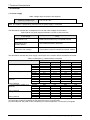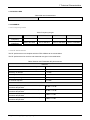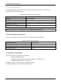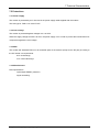
1
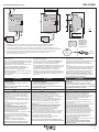
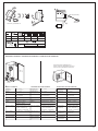
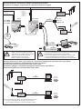
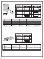
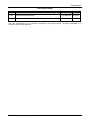
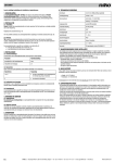
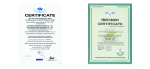
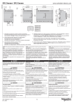
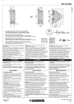
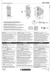
 Технический паспорт
продукта
Характеристики
SR2MOD02
GSM модем
Семейство продуктов
Zelio Logic
Тип изделия или компонента
Модем GSM
Состав комплекта
1 антенна с кабелем
1 кабель питания
2 монтажных ушка для крепления к панели
Крепление на DIN рейке (в сборе с GSM модемом)
Модем GSM
Тип модема
Типовой 4-диап. 900/1800 МГц, 850/1900 МГц
Доступные функции
Контроль обновления микропрограммного обеспечения
Отправка аварийного сигнала/получение инструкции
Отправка аварийного сигнала по электронному
адресу
Перенос программы
Резервируемые данные
Флеш-память
[Us] номинальное напряжение питания
12...24 V пост. ток
Дополнительно
Кол-во сообщений
≤ 28
Сохраняемые данные
Дата и время
Дискретное и цифровое значение
По телефону/e-mail
Пределы напряжения питания
5,5...32 V
Потребляемый ток
87 A 24 V
165 mA 12 V
≤ 2100 mA 5,5 В
Рассеиваемая мощность, Вт
2,1 W
Соответствующий номинал предохранителя
2,5 A
Электрическое соединение
1 антенна с кабелем
1 кабель
1 кабель Com-M Com-M специализированный для Zelio последовательный
RS232 , специальный коммуникационный протокол Zelio для связь с модемом, команды ТА
1 кабель Com-Z Com-Z специализированный для Zelio , специальный коммуникационный протокол Zelio для интеллектуальные реле Zelio Logic SR.B.....
и SR2 E..... версия (>= V3.1)
Кабель питания
Длина кабеля
1,5 m кабель питания
2,5 m антенна с кабелем
Изоляция
1780 В оптопара , тип разъема: Com-Z специализированный для Zelio
Кабелем R2 CBL07 , тип разъема: Com-M специализированный для Zelio
Тип подключения
Винтовые зажимы , 1 x 0,25...1 x 2,5 мм² , 24...14 , гибкий кабели с кабельным наконечником
Винтовые зажимы , 2 x 0,25...2 x 1,5 мм² , 23...16 , сплошной кабели
Винтовые зажимы , 1 x 0,25...1 x 2,5 мм² , 24...14 , полутвердый кабели
Винтовые зажимы , 1 x 0,25...1 x 2,5 мм² , 24...14 , сплошной кабели
Винтовые зажимы , 2 x 0,25...2 x 0,75 мм² , 24...18 , гибкий кабели с кабельным наконечником
Момент затяжки
0,5 N.m
Масса продукта
0,335 kg
18.02.2011
1
The information provided in this documentation contains general descriptions and/or technical characteristics of the performance of the products contained herein.
This documentation is not intended as a substitute for and is not to be used for determining suitability or reliability of these products for specific user applications.
It is the duty of any such user or integrator to perform the appropriate and complete risk analysis, evaluation and testing of the products with respect to the relevant specific application or use thereof.
Neither Schneider Electric Industries SAS nor any of its affiliates or subsidiaries shall be responsible or liable for misuse of the information contained herein.
Главная
Окружающая среда
Сертификаты продуктов
C-Tick
CSA
FCC часть 15 стандарт
GOST
IC
PTCRB
UL
Стандарты
EN/IEC 60068-2-32
EN/IEC 60068-2-6 Fc
Электромагнитная совместимость
Испытание на невосприимчивость к коммутационным помехам/коротким пакетам уровень 1 EN/IEC 61000-4-4
Испытание стойкости к с электролитическому разряду уровень 2 контакт EN/
IEC 61000-4-2
Испытание стойкости к с электролитическому разряду уровень 3 воздух EN/
IEC 61000-4-2
Испытание стойкости к электромагнитному полю EN/IEC 61000-4-3
Проверка стойкости к наведенным РЧ помехам уровень 2 EN/IEC 61000-4-6
Cтепень защиты IP
IP31 соответствует требованиям IEC 60529
Характеристики окружающей среды
Директива R & TTE соответствует требованиям ETSI EN 301419-1
Директива R & TTE соответствует требованиям ETSI EN 301489-7
Директива R & TTE соответствует требованиям ETSI EN 301511
Директива по ЭМС соответствует требованиям EN 301489-1
Директива по низковольтному оборудованию соответствует требованиям
EN/IEC 60950-1
Помеха излучаемая/наведенная
Класс B соответствует требованиям EN 55022-11 группа 1
Степень загрязнения
2 соответствует требованиям EN/IEC 61131-2
Температура окружающей среды при работе
-20...55 °C соответствует требованиям МЭК 60068-2-1 и МЭК 60068-2-2
Температура окружающей среды при хранении
-40...70 °C
Рабочая высота
2000 m
Максимальная высота при транспортировке
≤ 3048 m
Относительная влажность
95 % при 55 °C без образования конденсата
95 % без образования конденсата во время хранения
Дата европейского сертификата соответствия
RoHS
4Q2009
Состояние европейского сертификата RoHS
Будет соответствовать
2
SR2 COM01
www.telemecanique.com
1500 0395
71,2/2.8
2
12-24 V DC
27.5
1.08
59,9/2.35
12-24 V DC
COM-M
STATUSU/Run
U/Run
27.5
1.08
STATUSU/Run
108
4.25
COM-M
35
1.37
SR2COM01
100
3.93
SR2COM01
90
3.54
1
3
L = 300
L = 11.81
1
mm
inch
57/2.24
70/2.75
COM-Z
COM-Z
SR2MAN01EN
SR2MAN01FR
SR2MAN01DE
SR2MAN01SP
SR2MAN01IT
SR2MAN01PO
1 - Retractable mounting feet / Pattes de fixations retractables / Einziehbare Befestigungslaschen /
Patas de fijaciones retractables / Asole estraibili di fissaggio / Patilhas de fixação retrácteis
2 - Power supply terminals / Borniers à vis d'alimentation / Schraubklemmen für die Anschlusspannung /
Terminales de tornillos de alimentación / Morsettiera di alimentazione / Terminais de parafusos alimentação
3 - 35 mm rail clip-in spring / Ressort de clipsage sur rail de 35 mm / Klemmfeder auf 35 mm Schiene /
Resorte de clipsado en carril 35 mm / Molla di aggancio su barra metallica da 35 mm /
Mola de engate sobre carril de 35 mm
IMPORTANT : This document provides installation
instructions only.
Refer to User Manual #SR2MAN01EN for complete
Zelio 2 set-up, operation and software instructions.
Those responsible for the application,
implementation or use of this product must ensure
that the necessary design considerations
have been incorporated into each application,
completely adhering to applicable laws,
performance and safety requirements, regulations,
codes and standards.
The customer is responsible for all consequences
of the application.
DANGER
IMPORTANT : Ce document ne fournit que des
instructions d'installation.
Reportez-vous au Manuel Utilisateur #SR2MAN01FR
pour des instructions concernant outre l'installation,
le fonctionnement et la partie logicielle Zelio 2.
Les responsables de l'application, de la mise en œuvre
ou de l'utilisation de ce produit doivent s'assurer que les
considérations nécessaires de conception ont été
incorporées à chaque application, en parfaite
adéquation aux lois, aux besoins de performance et
de sécurité, la réglementation, aux normes et standards.
Le client est responsable des conséquences de son
application.
DANGER
CDROM
SR2 SFT01
V u 3.1
IMPORTANTE: Este documento solo contiene
instrucciones para la instalación.
Consulte el manual de instrucciones # SR2MAN01SP
para obtener informaciones más allá de la
instalación, del funcionamiento y del programa
Zelio 2.
Los responsables de la aplicación, implementación
o uso de este producto deben asegurarse que las
consideraciones de diseño necesarias hansido
incorporadas en cada aplicación,completamente
de acuerdo con las leyes, requirimientos de
rendimiento y seguridad, regulaciones, códigos y
modelos aplicables. El cliente esta responsable
de la consecuencia de su aplicación.
PELIGRO
HAZARD OF ELECTRIC SHOCK, EXPLOSION
OR ARC FLASH
- Turn power off before installing, removing,
wiring or maintaining.
RISQUE D'ELECTROCUTION, D'EXPLOSION
OU D'ARC ELECTRIQUE
- Coupez l'alimentation avant d'installer, de câbler ou
d'effectuer une opération de maintenance.
RIESGO DE ELECTROCUCION, DE EXPLOSION
O DE ARCO
- Desconecte la alimentación antes de realizar
los procesos de instalación, cableado, o mantenimiento.
Failure to follow this instruction will result in
death or serious injury.
Le non-respect de cette instruction entraînera la mort
ou des blessures graves.
Si no se respetan estas instrucciones, se producirán
graves daños corporales o la muerte.
WARNING
EXPLOSION HAZARD
- According to CSA C22.2 No 213: This equipment
is suitable for use in class I, division 2, groups
A, B, C and D or non-hazardous locations only.
Substitution of components may impair suitability
for class I, division 2.
- Confirm that the product power supply voltage
and its tolerances are compatible with those of the
network.
- Do not disconnect equipment unless power has
been switched off or the area is known to be
non-hazardous.
UNINTENDED EQUIPMENT OPERATION
- This product is not intended for use in safety
critical machine functions. Where personnel and
or equipment hazard exist, use appropriate
hard-wired safety interlocks.
- Do not disassemble, repair or modify the controllers.
- This controller is designed for use within an
enclosure according to specifications described in
these instructions in the paragraph on installation
conditions.
- Install the controllers in the operating
environement conditions described below.
Failure to follow this instruction can result in
death, serious injury or equipment damage.
AVERTISSEMENT
ADVERTENCIA
RISQUE D'EXPLOSION
- Selon CSA C22.2 No 213: cet équipement est
acceptable pour utilisation dans les endroits dangereux
de classe I, division 2, groupes A, B, C et D ou non
classifiés seulement. Le remplacement des composants peut
affecter l'utilisation en classe I, division 2.
- Assurez-vous que la tension d'alimentation du produit,
avec ses tolérances, est compatible avec celles du réseau.
- Assurez-vous que l'alimentation est coupée ou que
la zone ne présente aucun danger avant de connecter
l'équipement.
OPERATION D'EQUIPEMENT NON INTENTIONNELLE
- Ce produit ne doit pas être utilisé dans des fonctions
critiques de machine de sûreté. Là où il existe des
risques pour le personnel et/ou le matériel, utilisez
les contacts de sécurité câblés appropriés.
- Veuillez ne pas démonter, réparer, ni modifier le contrôleur.
- Ce contrôleur logique doit être utilisé dans une enceinte
fermée, selon les spécifications décrites dans cette notice,
au paragraphe Conditions d'installation.
- Installez les contrôleurs dans un environnement de
fonctionnement normal, comme indiqué.
RIESGO DE EXPLOSION
- Segun CSA C22.2 No 213: Este aparato esta
preparado para trabajar dentro de ambientes
peligrosos de classe I, Division 2, grupos A, B, C, y D
o unicamente en lugares no peligrosos. Reemplazar
componentes puede perjudicar la adecuación
para la clase I, división 2.
- Asegúrese de que la tensión de alimentación del
producto y sus tolerancias son compatibles con las
de la red eléctrica.
- No conecte el equipo a menos que se haya eliminado
la alimentación o que la zona no sea peligrosa.
OPERACION DEL EQUIPO INVOLUNTARIA
- Este producto no esta diseñado para un uso en
funciones criticas de una maquina de seguridad.
Donde existan riesgos para el personal o el equipamiento, use cierres de seguridad cableados adaptados.
- No desmonte, repare ni modifique los productos.
- Este producto esta diseñado para un uso en un
recinto cerrado, según las especificaciones que se
describen en estas instrucciones, al apartado
Condiciones de Instalación.
- Instale los productos en las condiciones de entorno de
funcionamiento descritas.
Le non-respect de cette directive peut entraîner la mort,
des lésions corporelles graves ou des dommages matériels. Si no se respetan estas precauciones pueden
producirse graves lesiones, daños materiales
o incluso la muerte.
W9 1606366 01 11 A03
02 - 2008
1/4
1
12-24 V DC
SR2COM01
COM-M
2
M4 x 20 (# 8 x 32 )
STATUS
U/Run
2
Click!
1 Nm
8.8 Ib/in
1
Rail 35 mm IEC/EN 60715
COM-Z
mm
inch
6,8
0.27
6,8
0.27
6,8
0.27
mm2
0.25…2.5
0.25…0.75
0.2…2.5
0.2…2.5
0.2…1.5
AWG
24…14
24…18
25…14
25…14
25…16
C
Ø 3,5
(0.14 in)
C
Nm
0,5
lb-in
4.5
Installation conditions / Conditions d'installation / Condiciones de instalación
Power factor (CSA Certification) 25 %
Facteur de marche (Certification CSA) 25 %
Factor de marcha (Certificación CSA) 25 %
55 °C
131 °F
40 °C
104 °F
2 m/s
>
Service conditions
Conditions de fonctionnement
Condiciones de funcionamiento
Operating
temperature
- 20…+ 55 °C
(- 4 °F…+ 131 °F)
Température de
fonctionnement
- 20…+ 55 °C
Temperatura de
funcionamiento
- 20…+ 55 °C
Storage
temperature
- 40…+ 70 °C
(- 40 °F…+ 158 °F)
Température de
stockage
- 40…+ 70 °C
Temperatura de
almacenamiento
- 40…+ 70 °C
Relative Humidity
Level RH1, 30…95 %
(non-condensing)
Humidité relative
Niveau RH1, 30…95 %
(sans-condensation)
Humedad relativa
Nivel RH1, del 30…95 %
(no condensante)
Pollution Degree
2 (IEC/EN 61131-2)
Degré de pollution
2 (IEC/EN 61131-2)
Grado de
contaminación
2 (IEC/EN 61131-2)
Degré de protection
IP 20 (IEC 60529)
Grado de proteción
IP 20 (IEC 60529)
Altitude
Fonctionnement : 0…2000 m
Altitud
Utilización : 0…2000 m
Degree of Protection IP 20 (IEC 60529)
Altitude
Operations: 0…2000 m
(0…6562 ft)
Transport: 0…3048 m
(0…10000 ft)
Transport : 0…3048 m
Tenue aux vibrations
(IEC 60068-2-6)
Transporte : 0…3048 m
Resistencia a las
vibraciones
(IEC 60068-2-6)
Vibration resistance
(IEC 60068-2-6)
Mounting on rail or panel 5…9 Hz,
amplitude: 3,5 mm (0.14 in)
9…150 Hz, acceleration: 1 g
10 cycles/axis, 1 octave/minute
10 cycles/axe, 1 octave/minute
Shock resistance
(IEC 60068-2-27)
147 m/sec2 (15 g), 11 ms duration, Tenue aux chocs
(IEC 60068-2-27)
3 shocks per axis.
147 m/sec2 (15 g), durée 11 msec, Resistencia mecanica 147 m/sec2 (15 g),
3 chocs par axe sur les trois axes a los golpes
duración 11 msec,
(IEC 60068-2-27)
3 golpes por eje.
Enclosure material
Self-extinguishable
Matière boitier
IEC/EN 61131-2
Normes applicable/
conditions
de fonctionnement
Standard applicable/
operating conditions
En montage sur rail et panneau :
5…9 Hz, amplitude : 3,5 mm,
9…150 Hz, accélération : 1 g
En montaje en carril y panel
5…9 Hz, amplitud: 3.5 mm
9…150 Hz, aceleración: 1 g
10 cyclos/eje, 1 octava/minuto
Auto-extinguible
Material caja
Autoextinguible
IEC/EN 61131-2
Norma de aplicación/
condiciones
de funcionamiento
IEC/EN 61131-2
W9 1606366 01 11 A03
2/4
Wiring architecture / Architecture câblage / Verkabelungsarchitektur /
Architettura di cablaggio / Arquitectura de cableado / Esquema de ligação
c 12-24 V
c 12 V
c 24 V
a 24 V
a 100-240 V
(1) 1 A Fuse
Fusible 1 A
Sicherung 1A
Fusible 1 A
Fusibile 1 A
Fusível 1 A
(1)
Zelio 2
SR2 Bppppp
SR2 Eppppp
SR3 Bppppp
I1
I2
I3
I4
I5
I6
IB
PSTN Modem
SR2 MOD01
(1)
(2)
SR2 CBL07
500/19.69
Zelio 2 COM
IC
12-24 V DC
24VDC
Ou / Or /
oder / O /
Oppure / Ou
SR2COM01
SR2 COM01
COM-M
c 12-24 V
STATUS
U/Run
Outputs
4 x relay 240V / 8 A
1
Q1 2
1
2
Q2 2
1
1
Q3 2
1
GSM Modem
SR2 MOD02
Q4 2
(3)
300/11.81
850/900/1800/1900 MHz
V u 3.xx
(2)
SR2 USB01
soft 2
CDROM
SR2 SFT01
3000/118.11
CDROM
SR2 SFT01
(2)
Zelio
(2)
mm
inch
Only use specfied cable
Utiliser uniquement les câbles spécifiques
Ausschließlich das spezielle Kabel verwenden
Utilizar únicamente el cable específico
Utilizzare soltanto il cavo specifico
Utilizar unicamente o cabo específico
SR2 CBL01
3000/118.11
Utilization of the SR2 MEM01/02 is incompatible with the SR2 COM1.
L'usage de la SR2 MEM01/02 est incompatible avec le SR2 COM01
SR2 MEM01/02 ist mit SR2 COM1 nicht kompatibel
El uso de la SR2 MEM01/02 es incompatible con el SR2 COM1.
L'uso della SR2 MEM01/02 è incompatibile con l'SR2 COM1
A utilização da SR2 MEM01/02 é incompatível com a SR2 COM1.
Wiring architecture for Zelio Logic Alarm use / Architecture câblage pour utilisation Zelio Logic Alarm /
Verkabelungsarchitektur für die Verwendung von Zelio Logic Alarm /
Arquitectura Cableado para utilización Zelio Logic Alarm /
Architettura cablaggio e architettura cablaggio per utilizzo allarme logico ZELIO /
Esquema de ligação para utilização Zelio Logic Alarm
(2)
PSTN Modem
SR2 MOD01
SR1 CBL03
Zelio Logic
Alarm
1800/70.87
CDROM
SR2 SFT02
c 12-24 V
c 12-24 V
(2)
GSM Modem
SR2 MOD02
(3)
SR1 CBL03
1800/70.87
Zelio Logic
Alarm
CDROM
SR2 SFT02
850/900/1800/1900 MHz
(3)
Not recommended for Japan / Non recommandé pour le Japon /
Für Japan nicht geeignet / No se recomienda para Japón /
Non consigliato per Giappone / Não recomendado no Japão.
W9 1606366 01 11 A03
3/4
SR2COM01 STATUS
12-24 V DC
Yellow / Jaune / Gelb /
Giallo / Amarillo /Amarelo
Green / Vert / Grün /
Verde / Verde / Verde
Status / Etat / Status /
Stato / Estado / Estado
SR2COM01
COM-M
1
No power
2
Modem fault
3
–
–
–
–
–
–
–
–
Zelio 2 fault
–
–
–
–
–
4
Internal fault
–
–
–
–
–
5
Zelio 2 and modem
detected
–
–
6
COM-M dialog
in progress
–
7
Zelio Soft 2 dialog
in progress/Message OFF
–
STATUS
Green/Yellow
COM-Z
FR
1
2
3
4
5
6
7
DE
ES
–
–
–
–
–
–
–
–
–
–
IT
–
PT
Non alimenté
Keine Stromversorgung
No alimentado
Non alimentato
Sem Alimentação
Défaut Modem
Modemfehler
Fallo Módem
Guasto modem
Falha do Modem
Défaut Zelio 2
Zelio 2-Fehler
Fallo Zelio 2
Guasto Zelio 2
Falha do Zelio 2
Défaut interne
Interner Fehler
Fallo interno
Guasto interno
Falha interna
Zelio 2 et modem détectés
Zelio 2 und Modem ermittelt
Zelio 2 y Módem detectados
Zelio 2 e modem rilevati
Zelio 2 e modem detectados
Dialogue COM-M en cours
COM-M-Dialog wird aufgebaut
Diálogo COM-M en curso
Dialogo COM-M in corso
Diálogo COM-M em curso
Dialogue Zelio Soft 2 en cours/ Zelio Soft 2-Dialog wird aufgebaut/ Diálogo Zelio Soft 2 en curso/ Dialogo Zelio Soft 2 in corso/
Meldung AUS
Message OFF
Mensaje OFF
Messaggio OFF
SR2 MOD02 LED
Dálogo Zelio Soft 2 em curso/
Mensagem DESLIGADO
Yellow / Jaune / Gelb /
Giallo / Amarillo / Amarelo
Status / Etat / Status /
Stato / Estado / Estado
LED
SR2 MOD02
FR
1
Not ready
2
Ready but not connected
to network
–
3
Ready and connected to
network
–
–
4
Transmission mode
–
–
–
DE
–
–
ES
IT
PT
1
2
Non prêt
Nicht betriebsbereit
No listo
Non pronto
Não preparado
Prêt mais non connecté
au réseau
Betriebsbereit, aber nicht mit
Netzwerk verbunden
Listo pero no conectado
a la red
Pronto ma non connesso
alla rete
Preparado mas não ligado
à rede
3
Prêt et connecté au réseau
Betriebsbereit und mit Netzwerk
verbunden
Listo y conectado a la red
Pronto e connesso alla rete
Preparado e ligado à rede
4
Mode de transmission
Übertragungsmodus
Modo transmisión
Modalità di trasmissione
Modo de transmissão
W9 1606366 01 11 A03
4/4
Schneider Electric
Modem
User Guide
EG_SR2MOD0x_SE_1002_UG_000_UK
04/2008
Presentation
Document history
Revision Modifications
000
CREATION (VERSION UK)
Author
Date
F. LE BRETON
16/04/08
The main modifications in this document compared to its previous version, are easily identifiable on a
monitor by means of the blue text.
EG_SR2MOD0x_SE_1002_UG_000_UK - 04/2008
3
Presentation
CONTENTS
PRESENTATION............................................................................................................................................... 6
HAZARD CATEGORIES AND SPECIAL SYMBOLS........................................................................................ 7
COPYRIGHT AND DISCLAIMER...................................................................................................................... 9
1 REFERENCES ............................................................................................................................................. 10
1.1 PRODUCTS REFERENCES ............................................................................................................................. 10
1.2 ABBREVIATIONS ........................................................................................................................................... 11
2 PACKING...................................................................................................................................................... 13
2.1 CONTENTS ................................................................................................................................................... 13
2.2 PACKING CASE ............................................................................................................................................ 14
2.3 MODEM LABELS ........................................................................................................................................... 14
3 GENERAL PRESENTATION ....................................................................................................................... 15
3.1 PHYSICAL DESCRIPTION ............................................................................................................................... 15
3.2 EXTERNAL CONNECTIONS ............................................................................................................................. 16
3.2.1 Connections ................................................................................................................................... 16
3.2.1.1 GSM antenna connector......................................................................................................... 16
3.2.1.2 4-pins Micro FIT female connector......................................................................................... 16
3.2.1.3 9-pins Sub-D female connector .............................................................................................. 16
3.2.2 Accessories.................................................................................................................................... 17
3.2.2.1 2-wires micro FIT supply cable............................................................................................... 17
3.2.2.2 GSM magnetic Antenna (SMA-M).......................................................................................... 17
4 USING THE MODEM ................................................................................................................................... 18
4.1 STARTING WITH THE MODEM ......................................................................................................................... 18
4.1.1 Mounting/Removal ......................................................................................................................... 18
4.1.1.1 Using DIN (35 mm) Rail mounting clip ................................................................................... 18
4.1.1.2 Mounting the modem with 2 mounting brackets..................................................................... 19
4.1.2 Modem Installation......................................................................................................................... 19
4.1.3 Network Bands Scanning............................................................................................................... 20
4.1.4 GSM LED ....................................................................................................................................... 20
4.1.5 Modem configuration PC side under Windows XP ........................................................................ 21
5 MODEM COMMUNICATION........................................................................................................................ 26
5.1 VERIFYING MODEM COMMUNICATION ............................................................................................................. 26
5.2 AT COMMANDS ECHO DEACTIVATED .............................................................................................................. 27
5.3 VERIFYING GSM RECEIVE SIGNAL QUALITY .................................................................................................... 28
5.4 VERIFYING THE PIN CODE ............................................................................................................................ 29
5.5 VERIFYING MODEM REGISTRATION ON THE GSM NETWORK ............................................................................ 29
5.6 MAIN AT COMMANDS (HAYES) .................................................................................................................... 30
5.7 POWERING DOWN THE UNIT .......................................................................................................................... 31
5.8 RS232 (V24) COMMUNICATION PROBLEM ..................................................................................................... 31
5.9 "ERROR" MESSAGE .................................................................................................................................... 32
5.10 "NO CARRIER" MESSAGE ......................................................................................................................... 32
6 FUNCTIONAL DESCRIPTION ..................................................................................................................... 34
6.1 ARCHITECTURE ............................................................................................................................................ 34
6.2 POWER SUPPLY ........................................................................................................................................... 34
6.2.1 General .......................................................................................................................................... 34
6.2.2 Protections ..................................................................................................................................... 34
6.3 RS232 SERIAL LINK ...................................................................................................................................... 35
6.3.1 General .......................................................................................................................................... 35
6.3.2 Mode Autobauding......................................................................................................................... 36
6.3.3 Pins description.............................................................................................................................. 36
7 TECHNICAL CHARACTERISTICS .............................................................................................................. 37
4
EG_SR2MOD0x_SE_1002_UG_000_UK - 04/2008
Presentation
7.1 MECHANICAL................................................................................................................................................ 37
7.2 ELECTRICAL ................................................................................................................................................. 38
7.2.1 Power supply ................................................................................................................................. 38
7.2.2 Interface SIM.................................................................................................................................. 39
7.2.3 GSM/DCS ...................................................................................................................................... 39
7.2.3.1 Frequency bands.................................................................................................................... 39
7.2.3.2 RF Performances ................................................................................................................... 39
7.2.3.3 External GSM Antenna........................................................................................................... 40
7.3 ENVIRONMENTAL CHARACTERISTICS.............................................................................................................. 40
7.4 STANDARDS / CONFORMITIES ....................................................................................................................... 40
7.5 PROTECTIONS .............................................................................................................................................. 41
7.5.1 Power supply ................................................................................................................................. 41
7.5.2 Over-voltage .................................................................................................................................. 41
7.5.3 ESD................................................................................................................................................ 41
7.5.4 Miscellaneous ................................................................................................................................ 41
8 SECURITY RECOMMENDATIONS ............................................................................................................. 42
8.1 GENERAL ..................................................................................................................................................... 42
8.2 SECURITY IN A VEHICLE ................................................................................................................................ 43
8.3 CARE AND MAINTENANCE .............................................................................................................................. 43
8.4 YOUR RESPONSIBILITY .................................................................................................................................. 43
EG_SR2MOD0x_SE_1002_UG_000_UK - 04/2008
5
Presentation
Presentation
Entirely dedicated to the wireless markets throughout the world, the Modem allows a simple and rapid
integration of GSM / GPRS connectivity into M2M applications.
The Modem used the Wavecom Module Quad-Band version 850/900/1800/1900 MHz (Europe Bands:
900/1800 MHz and US Bands: 850/1900 MHz) and GSM/GPRS Class 10.
The Modem references are according to ranges as follows:
•
•
6
Smart Relays: Zelio Logic of Schneider Electric
–
Modem reference: SR2 MOD02
–
Identified by marking on the Modem and the labels
Programmable Controllers: Twido of Schneider Electric
–
Modem reference: SR2 MOD03
–
Identified by marking on the Modem and the labels.
EG_SR2MOD0x_SE_1002_UG_000_UK - 04/2008
Hazard Categories and Special Symbols
Hazard Categories and Special Symbols
The following symbols and special messages may appear in this manual or on the equipment to warn of
potential hazards or to call attention to information that clarifies or simplifies a procedure.
A lightning bolt or ANSI man symbol in a “Danger” or “Warning” safety label on the equipment indicates an
electrical hazard which, as indicated below, can or will result in personal injury if the instructions are not
followed.
The exclamation point symbol in a safety message in a manual indicates potential personal injury hazards.
Obey all safety messages introduced by this symbol to avoid possible injury or death.
Symbol
Name
Lightning Bolt
ANSI Man
Exclamation Point
DANGER
DANGER indicates an imminently hazardous situation which, if not avoided, will result in death or
serious injury.
WARNING
WARNING indicates a potentially hazardous situation which, if not avoided, can result in death or
serious injury.
CAUTION
CAUTION indicates a potentially hazardous situation which, if not avoided, can result in minor or
moderate injury.
CAUTION
CAUTION used without the safety alert symbol, indicates a potentially hazardous situation which, if
not avoided, can result in property damage.
EG_SR2MOD0x_SE_1002_UG_000_UK - 04/2008
7
Hazard Categories and Special Symbols
WARNING
LOSS OF CONTROL
• The designer of any control scheme must consider the potential failure modes of control paths
and, for certain critical control functions, provide a means to achieve a safe state during and
after a path failure. Examples of critical control functions are emergency stop and overtravel
stop.
• Separate or redundant control paths must be provided for critical control functions.
• System control paths may include communication links. Consideration must be given to the
implications of unanticipated transmission delay or failures of the links.1
• Each implementation of a SR2 MOD02 or SR2 MOD03 modem must be individually and
thoroughly tested for proper operation before being placed into service.
Failure to follow these instructions can result in death, serious injury, or equipment
damage.
1
For additional information, refer to NEMA ICS 1.1 (latest edition), “Safety Guidelines for the
Application, Installation, and Maintenance of Solid State Control”
WARNING
HAZARD OF ELECTRIC SHOCK OR BURNS
• Do not open the modem.
• Modem must be powered using a 5 to 32 VDC power supply in GSM/DCS Class 2 (5.5 to
32 VDC in GPRS Class 10) using the supplied power cable.
• No internal user serviceable parts.
• Modem must be returned to the factory for any repairs.
Failure to follow these instructions can result in death, serious injury, or equipment
damage.
CAUTION
EQUIPMENT DAMAGE
• Do not connect.a supply voltage to pins 3 and 4.
• Do not use pins 3 and 4.
Failure to follow these instructions can result in death, serious injury, or equipment
damage.
DANGER
UNINTENDED EQUIPMENT OPERATION
The GSM modem must be turned off in the following situations:
• On an aircraft. The use of cellular telephones can be hazardous to the operations of the plane,
disturb the cellular network, and is illegal. The non-observance of this instruction can lead to
the suspension of cellular telephone services as well as a fine.
• At a refueling station.
• In any area with a potentially explosive atmosphere which could lead to an explosion or fire.
• In hospitals and similar places where medical equipment may be in use.
Failure to follow these instructions will result in death, serious injury, or equipment
damage.
8
EG_SR2MOD0x_SE_1002_UG_000_UK - 04/2008
Copyright and Disclaimer
Copyright and Disclaimer
All rights reserved. The reproduction, transfer, distribution or storage of part or the totality of the contents of
this document, in any form, mechanical or electronic, without the prior written authorization from Schneider
Electric is strictly prohibited.
Hayes is a registered trademark of Hayes Microcomputer Product Inc. The names of products and
companies mentioned in this document may be names or trademarks of their respective holders.
Use of certain products or services described in this document may require subscription or a paying
subscription. The availability of certain products or services described in this document can vary according to
the configurations and the materials.
In certain countries, restrictions of use of the equipment may apply. Contact your nearest legally qualified
local government representative for more information.
Schneider Electric operates a method of continuous development. Consequently, Schneider Electric
reserves the right to change and improve its products and documentation at any time and without notice.
The contents of this document are provided “as is”. All information contained herein is provided in good faith.
No responsibility can be assumed as to the precision and reliability of the contents of this document. Except
for the applicable obligatory laws, no guarantee in any form, explicit or implicit, including, but without being
limited to it, is granted as to the aptitude for marketing and suitability to a particular use. Schneider Electric
reserves the right to revise this document or to withdraw it at any time and without notice.
Schneider Electric cannot in any case to be held responsible for any loss of data or income, as well as
particular damage, incidental, consecutive or indirect.
In its continuing research into improving its products, Schneider Electric reserves the right to modify its
products and documentation at any time.
PLEASE NOTE:
Electrical equipment should be installed, operated, serviced, and maintained only by qualified personnel. No
responsibility is assumed by Schneider Electric for any consequences arising out of the use of this material.
© 2008 Schneider Electric. All Rights Reserved
EG_SR2MOD0x_SE_1002_UG_000_UK - 04/2008
9
1 References
1 References
1.1 Products References
The various features of the Modem are shown in the table below:
Modem
Functions GSM
- Quad-Bands 900/1800 and 850/1900 MHz
- ETSI GSM Phase 2+
Class 4 (2 W @ 850 / 900 MHz)
Class 1 (1 W @ 1800 / 1900 MHz)
- SIM Toolkit Release 99
DATA Features
- GPRS Class 10 (up to 4Rx / 2Tx)
- Supports PBCCH, Coding schemes: CS1 à CS4
- TCP/IP Library (PPPRFC, TCP Socket, UDP Socket, SMTP, POP3, FTP)
- Asynchronous data circuit, transparent and non-transparent, 9600 bps (standard) up to 14400 bps
(depending on network)
- Compatible Fax Group 3
- SMS point to point MT/MO and SMS CB
Memory Type
- Flash 32 Mbits and SRAM 4 Mbits (32/4)
Interfaces
- Antenna GSM: SMA-F connector
- Power Supply: +5.5 to +32 VDC (micro-FIT connector)
- RS232 + Audio via female 9-pin Sub-D connector
- AT Commands: GSM 07.05 and 07.07
- SIM reader (SIM 3 V – 1.8 V)
- DIN (35 mm) Rail mounting Clip
Supplied Accessories
- Mounting brackets (x2)
- Power Supply cable - 2-wire Micro FIT
- GSM magnetic Antenna (SMA-M)
10
EG_SR2MOD0x_SE_1002_UG_000_UK - 04/2008
1 References
1.2 Abbreviations
AC
ACM
AT
BTS
CLK
CMOS
CS
CTS
dB
dBc
dBi
dBm
DC
DCD
DCE
DCS
DSR
DTE
DTMF
DTR
EEPROM
EFR
E-GSM
EMC
EMI
ESD
ETSI
FIT
FR
FTA
GCF
GND
GPIO
GPRS
GSM
HR
I
IEC
IMEI
I/O
LED
MAX
ME
MIC
MIN
MNP
MO
MS
MT
NOM
O
Pa
PBCCH
Alternating Current
Accumulated Call Meter
ATtention (prefix for modem commands)
Base Transceiver Station
CLocK
Complementary Metal Oxide Semiconductor
Coding Scheme
Clear To Send
Decibel
Decibel relative to the Carrier power
Decibel relative to an Isotropic radiator
Decibel relative to one milliwatt
Direct Current
Data Carrier Detect
Data Communication Equipment
Digital Cellular System
Data Set Ready
Data Terminal Equipment
Dual Tone Multi-Frequency
Data Terminal Ready
Electrically Erasable Programmable Read-Only Memory
Enhanced Full Rate
Extended GSM
ElectroMagnetic Compatibility
ElectroMagnetic Interference
ElectroStatic Discharges
European Telecommunications Standards Institute
Series of connectors (micro-FIT)
Full Rate
Full Type Approval
Global Certification Forum
GrouND
General Purpose Input Output
General Packet Radio Service
Global System for Mobile communications
Half Rate
Input
International Electrotechnical Commission
International Mobile Equipment Identification
Input / Output
Light Emitting Diode
MAXimum
Mobile Equipment
MICrophone
MINimum
Microcom Networking Protocol
Mobile Originated
Mobile Station
Mobile Terminated
NOMinal
Output
Pascal (for speaker sound pressure measurements)
Packet Broadcast Control Channel
EG_SR2MOD0x_SE_1002_UG_000_UK - 04/2008
11
1 References
PC
PCL
PDP
PIN
PLMN
PUK
RF
RFI
RI
RMS
RTS
RX
SIM
SMA
SMS
SNR
SPI
SPL
SPK
SRAM
TCP/IP
TDMA
TU
TUHigh
TX
TYP
UTC
VSWR
12
Personal Computer
Power Control Level
Packet Data Protocol
Personal Identity Number
Public Land Mobile Network
Personal Unblocking Key
Radio Frequency
Radio Frequency Interference
Ring Indicator
Root Mean Square
Request To Send
Receive
Subscriber Identification Module
SubMiniature version A RF connector
Short Message Service
Signal-to-Noise Ratio
Serial Peripheral Interface
Sound Pressure Level
SPeaKer
Static RAM
Transmission Control Protocol / Internet Protocol
Time Division Multiple Access
Typical Urban fading profile
Typical Urban, High speed fading profile
Transmit
TYPical
Universal Time Clock
Voltage Stationary Wave Ratio
EG_SR2MOD0x_SE_1002_UG_000_UK - 04/2008
2 Packing
2 Packing
2.1 Contents
The Modem is supplied with:
- Modem packing case,
- The Modem,
- DIN (35 mm) Rail mounting clip,
- 2 mounting brackets,
- Instructions Sheet,
- 2-wire cable (Red/Black) with in-line fuse,
- GSM magnetic Antenna (SMA-M).
EG_SR2MOD0x_SE_1002_UG_000_UK - 04/2008
13
2 Packing
2.2 Packing Case
Packing case external dimensions:
- Width:
70 mm,
- Height:
70 mm,
- Length:
150 mm.
An identification label is affixed on the top of the packing case. It contains:
- The Schneider Electric logo,
- The product reference and information,
- CE mark.
Identification label dimensions:
- Height:
50 mm,
- Length:
80 mm.
2.3 Modem Labels
Two labels are affixed on the bottom part of the modem:
•
A production label provides the following information:
- The product reference,
- Crossed wheelie-bin mark (DEEE standard),
- Current, Voltage DC supply (VDC),
- The IMEI 15-digit bar code,
- Made by ERCO & GENER.
•
Additional marking:
- ROHS (2002/95/CE),
- CE mark,
- CSA,
- UL,
- FCC.
14
EG_SR2MOD0x_SE_1002_UG_000_UK - 04/2008
3 General Presentation
3 General Presentation
3.1 Physical Description
Description of the Modem:
3
1
4
2
N°
1
2
3
4
Description
Connector Micro-Fit 4-pins/M
DIN (35 mm) Rail Mounting clip
Connector Sub-D 9 pins/F
Front side
3
1
4
2
N°
1
2
3
4
Description
Rear side
SIM Card Cover
Connector SMA/F (GSM antenna)
GSM LED (see § 4.1.4)
EG_SR2MOD0x_SE_1002_UG_000_UK - 04/2008
15
3 General Presentation
3.2 External connections
3.2.1 Connections
3.2.1.1 GSM antenna connector
The GSM antenna connector is a 50 Ohms impedance female SMA type.
3.2.1.2 4-pins Micro FIT female connector
This connector allows the connection of an external DC supply.
Pin N°
1
2
3
4
Signal
+VDC
GND
NC
NC
CAUTION
EQUIPMENT DAMAGE
• Do not connect a supply voltage to pins 3 and 4.
• Do not use pins 3 and 4.
Failure to follow these instructions can result in death, serious injury, or equipment
damage.
3.2.1.3 9-pins Sub-D female connector
The 9-pins Sub-D female connector is used to connect the RS232 serial link.
PIN N°
1
2
3
4
5
6
7
8
9
16
Designation
Signal detection
Data reception
Data transmission
Data Terminal Ready
Ground
Data Set Ready
Request To Send
Clear To Send
Ring Indicator
Circuit (V24 – RS232C)
109 – DS – DCD
104 – RD – RXD
103 – ED – TXD
108/2 – TDP – DTR
102 – TS – GND
107 – PDP – DSR
105 – DPE – RTS
106 – PAE – CTS
125 – IA – RI
I/O
O
O
I
I
O
I
O
O
EG_SR2MOD0x_SE_1002_UG_000_UK - 04/2008
3 General Presentation
3.2.2 Accessories
3.2.2.1 2-wires micro FIT supply cable
The cable described below is supplied with the modem.
1
2
4
5
N°
1
2
3
4
5
3
Description
4-pin Micro FIT connector
Black wire (GND)
5 mm tinned copper wire
Red wire (+VDC)
Fuse 2.5 A/250 V Fast Blow (5x20 mm)
Component
Micro FIT connector
Cable
Wire
Characteristics
Male 4-pin
Length ≈ 1.5 m
Tinned copper 24 x 0.2 mm
Wire gauge: 0.75 mm²
3.2.2.2 GSM magnetic Antenna (SMA-M)
The GSM magnetic antenna is designed for a vertical use and must be put on a metallic support.
Its connection SMA Male allows it to be directly connected to the modem.
Component
Magnetic SMA-M Antenna
Coaxial Cable
Antenna Dimensions
EG_SR2MOD0x_SE_1002_UG_000_UK - 04/2008
Characteristics
Quad Bands
850/900/1800/1900 MHz
Length ≈ 2.5 m ± 10 cm
RG174 - Ø 2.54 mm
Base: Ø 30 mm
Total Height: 7 cm
17
4 Using the modem
4 Using the modem
4.1 Starting with the modem
4.1.1 Mounting/Removal
4.1.1.1 Using DIN (35 mm) Rail mounting clip
The modem is supplied with a DIN (35 mm) Rail mounting clip mounted on the case.
The DIN (35 mm) Rail mounting clip allows a fast and easy mounting/removal on an OMEGA DIN (35 mm)
Rail (IEC/EN 60715 / DIN (35 mm) 7.5 mm).
Step
1
2
3
4
5
18
Mounting the modem
Removing the modem
Action
Press the modem on DIN (35 mm) Rail.
Rotate to lock the modem on the Rail.
Press the modem on DIN (35 mm) Rail.
Rotate to unlock the modem on the Rail.
Take out the modem.
EG_SR2MOD0x_SE_1002_UG_000_UK - 04/2008
4 Using the modem
4.1.1.2 Mounting the modem with 2 mounting brackets
To mount the modem on a support, use the mounting brackets as shown in the diagram below:
Note:
- Must be mounted to a flat
surface.
- Maximum height of the
screw head height: 2 mm
Mounting brackets
Screws must
be unscrewed
for removal
Step
1
2
3
Action
Remove the 2 DIN (35 mm) Rail mounting clip screws.
Slide the support of the DIN (35 mm) Rail clip.
Insert the 2 mounting brackets.
4.1.2 Modem Installation
To install the modem, it is recommended to perform the following operations with the modem turned off:
Step
Action
1
2
3
4
5
6
Remove the SIM card cover on the rear side
Carefully insert the SIM card into its holder.
Put the SIM card cover on the rear side.
Connect the GSM antenna to the SMA connector.
Plug the 9-pins Sub-D connector of modem to the device by using the RS232 cable.
Connect the supply cable to an external regulated DC source.
Connect the supply cable to the modem and turn on the power supply. The modem
will control the network bands and the GSM LED will light up.
7
Insertion
Direction of the
SIM Card
The modem is now ready for use. If you used a PC (Terminal), refer to the chapter 5 for a description of the
commands for configuring and using the modem.
EG_SR2MOD0x_SE_1002_UG_000_UK - 04/2008
19
4 Using the modem
4.1.3 Network Bands Scanning
By default, the modem is configured to first automatically check the European network bands.
After insertion of SIM card Network bands scanning is activated. An embedded application automatically
checks the presence of a network. In case of absence, it switches to the US network bands and continues its
search. This cycle is repeated until a valid network is found.
The detected GSM network is stored in the modem.
In the case of use of new SIM card, a new network search procedure is automatically initialized.
Note: In the case of a modem configured with a SIM card for use in a specific area (European area for
instance) that is then to be used in a different area (US for instance), the SIM card must be removed while
modem is switched on. This is because a new network search procedure is automatically initialized after the
removal (or change) of the SIM card while the device is switched on.
4.1.4 GSM LED
The state of the modem is indicated by the GSM LED located on the rear side of the modem (see
chapter 3.1). The table below shows the meaning of the different states of the GSM LED:
GSM LED
ON
OFF
20
LED activity
LED on fixed
Modem state
The modem is powered, it is ready to function but not yet
recognized by the network; the PIN code has not yet been
entered or the antenna is not connected.
LED flashing
(once every 2 seconds)
The modem is powered, the PIN code is active, the modem is
recognized by the network and is ready to make or receive a
call (Idle mode).
LED flashing
(Once a second)
The modem is powered and currently in communication
(Voice, Data or Fax).
LED off
The modem is not powered or is in the RESET phase.
EG_SR2MOD0x_SE_1002_UG_000_UK - 04/2008
4 Using the modem
4.1.5 Modem configuration PC side under Windows XP
In order to use this modem PC side, it is necessary to install and configure this modem under Windows with
the same communication parameters: see chapter 5.1.
To add a modem under Windows, follow instructions below:
Step
Action
In the menu Start, Control panel, select « Phone and Modem Options »
The following window appears:
1
Click on « Modem » then « Add ».
The following window appears:
2
Check the box « Don’t detect my modem » and click on Next:
EG_SR2MOD0x_SE_1002_UG_000_UK - 04/2008
21
4 Using the modem
Step
Action
3
Choose a standard modem 56000 bps and click on « Next ».
4
Select the communication port where the modem is connected and click on « Next ».
Windows installs the modem.
22
EG_SR2MOD0x_SE_1002_UG_000_UK - 04/2008
4 Using the modem
Step
Action
After the modem is installed, it is necessary to configure the communication port link
to the modem:
5
Click on standard modem 56000 bps then on « Properties ».
Click on « Modem » and select 115200 as maximal port speed.
6
EG_SR2MOD0x_SE_1002_UG_000_UK - 04/2008
23
4 Using the modem
Step
Action
Click on « Advanced » then « Change Default Preferences »:
7
In the menu « General », select 115200 bps and None as Flow Control method.
8
24
EG_SR2MOD0x_SE_1002_UG_000_UK - 04/2008
4 Using the modem
Step
Action
Click on « Advanced » and the following window appears:
Enter the parameters according to the modem configuration (see chapter 5.1).
In the example below, the configuration is for the SR2 MOD02 Modem.
9
10
Reboot the PC and the modem. After that, the modem is operational.
EG_SR2MOD0x_SE_1002_UG_000_UK - 04/2008
25
5 Modem communication
5 Modem communication
5.1 Verifying modem communication
Connect the modem RS232 port to the PC COM port.
According to the type of modem, configure the DTE RS232 port as follows:
Zelio Logic (SR2 MOD02)
Twido (SR2 MOD03)
▪ Data rate: 115200 bauds,
▪ Data rate: 19200 bauds,
▪ Data size: 7 bits,
▪ Data size: 8 bits,
▪ Parity: Even Parity,
▪ Parity: No Parity,
▪ Stop bits: 1 Stop bit,
▪ Stop bits: 1 Stop bit,
▪ Flow control: hardware flow control activated,
▪ Flow control: hardware flow control deactivated,
▪ AT commands Echo: Echo deactivated,
▪ AT commands Echo: Echo deactivated,
▪ DSR Signal: DSR 1,
▪ DSR Signal: DSR OFF,
▪ Ring Register: S0=0 (no automatic answer).
▪ Ring Register: S0=2 (answer after 2 rings).
With the Windows HyperTerminal communication application, enter the command AT(CR). The modem
should reply with OK.
In the case where no communication can be established with the modem:
▪ Verify the RS232 connection between the DTE and the modem (DCE),
▪ Verify the configuration of the COM port on the DTE.
Some examples of AT commands which can be sent to the modem once the communication has been
established and verified (these commands are explained in detail later in the document):
▪ AT+CGSN: the modem should reply with a 15 digit number (beginning with "353311xxxxxxxxx").
▪ AT+CPIN=xxxx: enter the code of the SIM card xxxx (if active).
▪ AT+CSQ: verify the GSM signal reception level.
▪ AT+CREG ?: verify the registration of the modem on the network.
▪ ATD<telephone number>: start a voice call.
▪ ATH: hang-up (end of the call).
26
EG_SR2MOD0x_SE_1002_UG_000_UK - 04/2008
5 Modem communication
5.2 AT commands Echo deactivated
If “no echo” is returned when entering an AT command, it could be that:
- The modem’s echo function is deactivated (setting by default).
- The “Local echo” of your communication application is not activated.
The echo is configured by the command ATE and requires a back-up with the command AT&W.
To activate the modem echo, enter the command ATE1.
When using a communication application to send AT commands to the modem, it is recommended to:
- deactivate the "local echo" in your communication application,
- activate the modem echo (enter the command ATE1).
For a communication Machine to Machine with the modem, it is recommended to deactivate the modem
echo (enter the command ATE0) to avoid the CPU receiving redundant responses.
EG_SR2MOD0x_SE_1002_UG_000_UK - 04/2008
27
5 Modem communication
5.3 Verifying GSM receive signal quality
The modem will be able to establish a call only if the received GSM signal is of a sufficient level.
The command AT+CSQ will return the reception level (rssi) of the signal sent by the closest GSM Base
Transceiver Station (BTS), as well the receive bit error rate (ber).
When the SIM card is present and the PIN code has been entered, the command AT+CSQ will return the
signal level from the BTS on the subscribed operator network.
When used without the SIM card, this command will simply indicate the closest BTS due to the fact that the
modem cannot identify the current subscription. It is therefore advisable to make this test with the SIM card
present.
To verify the GSM signal quality, perform the following operations:
Using a communication application, enter the command AT+CSQ.
The response is in the following format:
+CSQ: <rssi>,<ber>
where: <rssi> = indicates the reception level,
<ber> = receive bit error rate.
Verify the value <rssi> with the aid of the table below:
<rssi> value
Gain (dbm)
Interpretation
<ber> value
0
-113 dbm
Insufficient
0 to 7
1 to 10
-111 to -95 dbm
Insufficient
11 to 30
-93 to -53 dbm
Sufficient
31 (max)
-51 dbm
Perfect
99
Unknown/not detectable
99
Interpretation
See standard ETSI
GSM 05.08
Unknown/not detectable
The GSM modem will function correctly with a minimum <rssi> of between 11 and 15.
Below 10 the signal is insufficient, the modem cannot function depending on the geographical situation or the
mobility of the vehicle. Above 15 the signal is of a sufficient level.
28
EG_SR2MOD0x_SE_1002_UG_000_UK - 04/2008
5 Modem communication
5.4 Verifying the PIN code
The PIN code is essential in order to make a call or to accept a call from the GSM network.
The PIN code is held on the SIM card and can be modified by the user.
To verify a previously entered PIN code, use a communication application and enter the command
AT+CPIN?
The table below shows the main responses from the modem:
Command
AT+CPIN?
Response
Interpretation
+CPIN: ERROR
The SIM card is absent or unknown
+CPIN: READY
The PIN code is correct
+CPIN: SIM PIN
The PIN code is bad or not yet entered
+CPIN: SIM PUK
The PUK code is required
5.5 Verifying modem registration on the GSM network
1. Ensure that a valid SIM card is present in the SIM card reader in the modem.
2. Using a communications application, enter the following AT commands:
a. AT+CPIN=xxxx Enter the PIN code. The user has only 3 attempts to enter the PIN code.
After the third attempt, only the PUK code (supplied by the operator) will allow a new PIN
code to be entered.
b. AT+CREG? Verify the network registration status. The response will be of the following
format: +CREG: <mode>,<stat> where:
<Mode> = un-solicited registration message configuration,
<Stat> = registration status
3. Verify the registration status with the aid of the following table:
Command
AT+CREG?
Response
Interpretation
+CREG: 0,0
The modem is not recognized by the network.
+CREG: 0,2
The modem is searching for a network operator.
+CREG: 0,1
The modem is GSM attached to a local operator.
+CREG: 0,5
The modem is GSM attached to an operator in
roaming mode.
If the modem is not registered, verify the antenna connection and the receive signal level (see chapter 5.3).
EG_SR2MOD0x_SE_1002_UG_000_UK - 04/2008
29
5 Modem communication
5.6 Main AT commands (HAYES)
The table below shows at a quick glance the main AT commands useful for the control of the modem.
Description
Enter the PIN code
Verification of GSM
network registration
AT Command
Response
AT+CPIN=xxxx
OK
PIN code accepted
(xxxx = PIN code)
+CME ERROR: 16
PIN code incorrect (1*)
+CME ERROR: 3
PIN code already entered (1*)
AT+CREG?
+CREG: 0,1
+CREG: 0,5
+CREG: 0,2
+CREG: 0,0
Reception of an
incoming call (2*)
Make a voice call
Interpretation
The modem is GSM attached to a
local operator.
The modem is GSM attached to an
operator in roaming mode.
The modem is searching for a
network operator.
The modem is not recognized by the
network.
ATA
OK
Reply to the call
ATD<telephone
number>;
OK
Communication established
+CME ERROR: 11
PIN code not entered
+CME ERROR: 3
The credit has run out or the
communication has already been
established.
Make an emergency
ATD112;
call (112)
OK
Communication established
Lost communication
NO CARRIER
(IMPORTANT: the ; at
the end of the sequence
specifies a voice call)
Hang-up
ATH
OK
(1*) The command AT+CMEE=1 allows the display of extended error codes. This command may be saved
with the command AT&W.
The command AT+WIND=63 allows the display of the change of status of the SIM card (present,
ready…) and to check divers modem states (modem ready after RESET…). This command may be
saved with the command AT&W.
(2*) The command AT+CRC=1 will in the case of an incoming call, display more detailed ring information
indicating the type of call - voice, data or fax. This command may be saved with the command AT&W.
Examples:
For VOICE: +CRING: VOICE
For DATA: +CRING: REL ASYNC
For FAX: +CRING: FAX
30
EG_SR2MOD0x_SE_1002_UG_000_UK - 04/2008
5 Modem communication
5.7 Powering down the unit
Do not cut off the supply of modem whilst in communication or dialogue without having first detached from
the network operator.
To avoid network congestion when powering down the modem, it is essential to first execute the command
AT+CPOF. If this is not done, then, in certain cases the modem can remain registered on the network.
Before cutting the power in dialog mode (no communication), send the following command to the modem:
AT+CPOF or AT+CFUN=0 (identical functioning).
The modem will return OK and is no longer registered on the network. The radio module is put into standby
and the power may then be removed.
5.8 RS232 (V24) Communication problem
If the modem does not respond to any of the AT commands via the RS232 then refer to the table below for a
list of possible causes and solutions.
If the modem...
Returns nothing
Check
Is the modem correctly powered?
Is the serial cable connected at
both ends (PC and Modem)?
Returns nothing or
random characters
Is the serial cable correctly cabled
according to the table in chapter
3.2.1.3?
Is the communications terminal
correctly configured on the PC?
Is there another application using
the same port thus creating a
conflict?
Is the modem echo deactivated
and without message reporting?
EG_SR2MOD0x_SE_1002_UG_000_UK - 04/2008
Action
Ensure that the modem is connected to an
external regulated power source 5.5V to 32V DC
(See chapter 6.2.1).
Verify the connection of the serial cable.
Cable the serial cable according to the table in
chapter 3.2.1.3.
Ensure that the terminal configuration
corresponds to that of the modem.
See chapter 5.1 for the factory configuration
according to the modems.
Close the conflicting application.
Enter the command ATE1Q0 followed by AT&W
if a backup is required.
31
5 Modem communication
5.9 "ERROR" message
The modem returns the message “ERROR” (in response to an AT command) in the following cases:
•
The COM port is not directed to the modem but to another modem. Enter the command ATI. The
response should be WAVECOM MODEM.... All other responses indicate a dialog with another
modem. Verify the COM port used in the communications application.
•
The syntax of the AT command is incorrect. Re-enter the command.
•
The syntax of the AT command is correct, but with incorrect parameters:
-
Enter the command AT+CMEE=1 to obtain an error message with its error code instead of a
simple “ERROR” message,
-
Enter again the AT command which previously caused a problem to obtain the error code. In
the case of an error, the response is in the form:
+CME ERROR: <error code> or +CMS ERROR: <error code>
Note: It is strongly recommended to systematically allow the modem to return error codes (enter the
command AT+CMEE=1).
5.10 "NO CARRIER" message
If the modem returns the message "NO CARRIER" after an attempted call (voice or data), check the table
below for a list of possible causes and solutions.
Modem returns...
Check
"NO CARRIER"
Is the received GSM signal
strong enough?
Is the modem registered on the
network?
Verify network registration (see chapter 5.5).
Is the antenna correctly
connected?
Check the GSM antenna installation.
"NO CARRIER"
Has the semi-colon (;) been
(when attempting entered immediately after the
a VOICE call)
telephone number in the AT
command?
"NO CARRIER"
Has the SIM card been
(when attempting configured for data / fax calls?
a DATA call)
Is the selected modulation type
supported by the called
number?
Is the selected modulation type
supported by the network?
32
Action
Verify the received signal quality (see chapter 5.3).
Ensure that the semi-colon (;) been entered
immediately after the telephone number in the AT
command, for example: ATD0123456789;
Ensure that the SIM card is allowed to make data /
fax calls (check with your SIM card supplier).
Ensure that the selected modulation type is supported
by the called number.
Ensure that the selected modulation type is supported
by the network. If not, select a compatible modulation
type with the command AT+CBST=0,0,1 .
EG_SR2MOD0x_SE_1002_UG_000_UK - 04/2008
5 Modem communication
If the modem returns the message "NO CARRIER", use the command AT+CEER to see the extended error
code.
Refer to the table below for a list of extended error codes and their meanings.
Error code
Meaning
1
Unassigned (unallocated) number
16
Normal call clearing
17
User busy
18
No user responding
19
User alerting, no answer
21
Call rejected
22
Number changed
31
Normal, unspecified
50
Requested facility not subscribed
68
ACM equal to or greater than ACMmax
252
Call barring on outgoing calls
253
Call barring on incoming calls
3, 6, 8,
Network cause
29, 34, 38, 41,
42, 43, 44, 47,
49, 57, 58, 63,
65, 69, 70, 79,
254
EG_SR2MOD0x_SE_1002_UG_000_UK - 04/2008
Observations
Check your subscription (data subscription
available?).
No more SIM card credit or card expired.
Check with the operator.
33
6 Functional Description
6 Functional Description
6.1 Architecture
6.2 Power Supply
6.2.1 General
The modem must be powered (V+BATTERY) by an external regulated DC power supply of in Safety Extra
Low Voltage (SELV) between +5.5 V and +32 V.
The modem’s various internal DC voltages are provided by an internal DC/DC converter.
If the input voltage (V+BATTERY) falls below 5.5 V, the modem will not operate correctly.
6.2.2 Protections
The modem is protected by an in-line 2.5 A / 250 V fast blow fuse in the power supply cable supplied with the
modem.
It also has internal protection against power supply spikes of more than 32 V.
Filter specifications:
Input/output EMI/RFI protection,
Signal smoothing.
34
EG_SR2MOD0x_SE_1002_UG_000_UK - 04/2008
6 Functional Description
6.3 RS232 serial link
6.3.1 General
The RS232 interface provides a level translation between the Wavecom GSM/GPRS Module (DCE) and the
PC COM port (DTE).
The RS232 interface is protected internally (ESD protection) against external electrostatic spikes.
Filter specifications:
Input/output EMI/RFI protection,
Signal smoothing.
The following signals are available:
TX data (CT103/TX)
RX data (CT104/RX)
Request To Send (CT105/RTS)
Clear To Send (CT106/CTS)
Data Terminal Ready (CT108-2/DTR)
Data Set Ready (CT107/DSR)
Data Carrier Detect (CT109/DCD)
Ring Indicator (CT125/RI)
RS232 signals
The RS232 interface allows a certain amount of flexibility in the use of its signals. For example, the modem
may operate in the 3-wire mode using only the TX, RX and GND signals. However, the CTS and RTS signals
will also be required for GPRS applications and X-Modem upgrade.
EG_SR2MOD0x_SE_1002_UG_000_UK - 04/2008
35
6 Functional Description
6.3.2 Mode Autobauding
The auto-baud mode allows the modem to automatically detect the transmission speed used by the DTE.
Only the following speeds will be detected: 2400, 4800, 9600, 19200, 38400, 57600 bps. Auto-baud
detection cannot be guaranteed for speeds below or above these speeds.
The auto-baud mode is controlled by the AT commands.
Note: See at chapter 5.1 for the default configuration of modems.
6.3.3 Pins description
Table: Pins description
Signal
Pin number
on Sub-D connector
I/O
RS232 standard
CTXD/CT103
2
I
TX
Transmit serial data
CRXD/CT104
3
O
RX
Receive serial data
CRTS/CT105
7
I
RTS
Request To Send
CCTS/CT106
8
O
CTS
Clear To Send
CDSR/CT107
6
O
DSR
Data Set Ready
CDTR/CT108-2
4
I
DTR
Data Terminal Ready
CDCD/CT109
1
O
DCD
Data Carrier Detect
CRI/CT125
9
O
RI
CT102/GND
5
36
Description
Ring Indicator
Ground
EG_SR2MOD0x_SE_1002_UG_000_UK - 04/2008
7 Technical Characteristics
7 Technical Characteristics
7.1 Mechanical
Table: Mechanical characteristics
Dimensions
Overall Dimensions
Weight
Volume
Case
Ingress Protection
73 x 54.5 x 25.5 mm (excluding connectors)
90 x 54.5 x 25.5 mm
≈ 88 g max. (modem only)
< 335 g max. (modem + accessories)
101.5 cm³
Extruded aluminum
IP31
The illustration below indicates the dimensions (in mm) of the modem showing the clearances necessary for
installation.
EG_SR2MOD0x_SE_1002_UG_000_UK - 04/2008
37
7 Technical Characteristics
7.2 Electrical
7.2.1 Power supply
Table: Voltage range and power consumptions
Operating voltage range
▪ 5.5 V to 32 V DC
Note: The modem is permanently powered once the power supply is connected.
The table below indicates the consequences of over and under-voltages to the modem.
Table: Effects of a power supply level below 5.5 VDC or above 32 VDC.
If the voltage:
Then:
▪ Falls bellow 5.5 V
▪ GSM communication may not operate properly.
▪ Goes above 32 V
(transient peaks)
▪ The modem has built in protection.
▪ Goes above 32 V
(continuous over-voltage)
▪ The modem is then protected by the in-line fuse.
(The modem is short-circuited by an internal varistor).
The table below indicates the power supply consumption of the modem without the RS232 connected.
Table: Consumption (1*) without RS232 connected
CONDITIONS
T = 25°C and 3 V SIM card
Idle mode (2*)
850/900 MHz
1800/1900 MHz
I Nom.(mA)
I Max.(mA)
I Nom.(mA)
I Max.(mA)
at 5.5V
17.5
23
17.5
23
at 12V
11.7
16.5
11.7
16.5
at 24V
10
14
10
14
at 32V
8.6
11.5
8.6
11.5
Idle mode 32K (3*)
at 5.5V
12
14.5
12
14.5
at 12V
9.2
11.3
9.2
11.3
at 24V
8
10.5
8
10.5
at 32V
7.7
9.7
7.7
9.7
In communication GSM
at 5.5V
182.5
195.5
135
145
1RX/1TX
at 12V
96
103.5
71.75
78
at 24V
50
54
37
40
Power (2W/1W)
at 32V
40
44.5
31
34.75
In communication GPRS CL10
at 5.5V
320
341
230
242
3RX/2TX
at 12V
165
177
120
127.5
at 24V
87
93
64
68
Power (2W/1W)
at 32V
67
72
50
53.5
During TX bursts
at 5.5V
1178
1400
670
780
at 12V
600
712
342
400
at 24V
320
375
180
220
Power (2W/1W)
at 32V
230
274
132
156
(1*) The power consumption may vary by 5% over the whole operating temperature range (-20 °C to +55 °C)
(2*) Idle mode: modem is registered on the network but not in communication.
(3*) Idle mode 32K: low power mode controlled by an external application, via the DTR CTS signals.
38
EG_SR2MOD0x_SE_1002_UG_000_UK - 04/2008
7 Technical Characteristics
7.2.2 Interface SIM
Table: SIM card characteristics
SIM Card
3 V or 1.8 V
7.2.3 GSM/DCS
7.2.3.1 Frequency bands
Table: Frequency ranges
Parameter
Transmission
Frequency
Reception
Frequency
GSM 850
E-GSM 900
DCS 1800
PCS 1900
824 to 849 MHz
880 to 915 MHz
1710 to 1785 MHz
1850 to 1910 MHz
869 to 894 MHz
925 to 960 MHz
1805 to 1880 MHz
1930 to 1990 MHz
7.2.3.2 RF Performances
The RF performances are compliant with the ETSI GSM 05.05 recommendation.
The RF performances for receiver and transmitter are given in the table below.
Table: Receiver and Transmitter RF performances
Receiver
E-GSM900/GSM850 Reference Sensitivity
- 104 dBm
DCS1800/PCS1900 Reference Sensitivity
- 102 dBm
Selectivity at 200 kHz
> +9 dBc
Selectivity at 400 kHz
> +41 dBc
Linear dynamic range
63 dB
Co-channel rejection
>= 9 dBc
Transmitter
Maximum output power (E-GSM900/GSM850)
at ambient temperature
33 dBm +/- 2 dB
Maximum output power (DCS1800/PCS1900)
at ambient temperature
30 dBm +/- 2 dB
Minimum output power ( E-GSM900/GSM850)
at ambient temperature
5 dBm +/- 5 dB
Minimum output power ( DCS1800/PCS1900 )
at ambient temperature
0 dBm +/- 5 dB
EG_SR2MOD0x_SE_1002_UG_000_UK - 04/2008
39
7 Technical Characteristics
7.2.3.3 External GSM Antenna
The external GSM antenna is connected to the modem via the SMA/M connector. It must have the
characteristics listed in the table below.
Table: External GSM antenna characteristics
Antenna frequency range
Quad-bands 850/900/1800/1900 MHz
Impedance
50 Ohms nominal
DC Impedance
0 Ohm
Gain (antenna + cable)
0 dBi (in a minimum direction)
VSWR (Rx max TX max)
1.5:1
Polarization
Linear
Note: See chapter 3.2.2.2, for GSM antenna recommended by Schneider Electric.
7.3 Environmental characteristics
For the correct operation of the modem, stay within the limits listed in the table below.
Table: Environmental characteristics
Operating temperature
-20 °C to +55 °C
Storage temperature
-40 °C to +70 °C
Operating humidity without condensation
HR < 95% at +55°C
Atmospheric pressure
normal
7.4 Standards / Conformities
The product conforms to the following requirements:
-
R&TTE 1999/5/EC Directive,
-
Regulations of standard ETSI EN 301 489-7, EN301 419-1 et EN 301 511,
-
2002/96/CE DEEE (crossed out wheelie bin).
The Modem conforms to the 2002/95/CE – ROHS requirements.
Conformity available on web-site www.telemecanique.com.
40
EG_SR2MOD0x_SE_1002_UG_000_UK - 04/2008
7 Technical Characteristics
7.5 Protections
7.5.1 Power supply
The modem is protected by an in-line fuse in the power supply cable supplied with the modem.
The fuse type is: FSD 2.5 A / 250 V FAST.
7.5.2 Over-voltage
The modem is protected against voltages over +32 VDC.
When the supply voltage exceeds +32 VDC, the power supply is cut in order to protect the internal electronic
components against the over-voltage.
7.5.3 ESD
The modem will withstand ESD’s on all accessible parts of the modem (except for the RF part) according to
the IEC 61000-4-2 requirements:
8 kV air discharge,
4 kV contact discharge.
7.5.4 Miscellaneous
Filter specifications:
Input/output EMI/RFI protection,
Signal smoothing.
EG_SR2MOD0x_SE_1002_UG_000_UK - 04/2008
41
8 Security Recommendations
8 Security Recommendations
8.1 General
It is important to follow the specific regulations for the use of radio operator equipment, in particular the
possible risks of radio frequency interference (RFI). Please follow carefully the security advice given below.
Turn off your GSM modem:
•
On an aircraft. The use of cellular telephones can endanger the operations of the plane, disturb the
cellular network and is illegal. The non-observance of this instruction can lead to the suspension of
cellular telephone services as well as a fine.
•
At a refueling station.
•
In any area with a potentially explosive atmosphere which could lead to an explosion or a fire.
•
In hospitals and similar places where medical equipment may be in use.
Restrictions of use of radio operator equipment in:
•
Fuel depots.
•
Chemical factories.
•
Locations where demolition is under way.
•
Other places where signs indicate that the use of cellular telephones is prohibited or dangerous.
•
Other places where you should normally turn off the engine of your vehicle.
There can be a hazard associated with the use of your GSM modem close to insufficiently protected medical
devices such as acoustic apparatus and pacemakers. Consult the manufacturers of medical equipment to
determine if it is adequately protected.
The use of your GSM modem close to other electronic equipment may also cause interference if the
equipment is insufficiently protected. Observe all the manufacturer’s warnings and recommendations for the
equipment.
The modem is designed to be used with “fixed” and “mobile” applications:
•
“Fixed application”: The GSM modem is physically connected to a site and it is not possible to be
easily moved to another site.
•
“Mobile application”: The GSM modem is designed to be used in various places (other than fixed)
and is intended for use in portable applications.
42
EG_SR2MOD0x_SE_1002_UG_000_UK - 04/2008
8 Security Recommendations
8.2 Security in a vehicle
Do not use your GSM modem whilst driving a vehicle, unless equipped with a correctly installed earpiece/hands-free kit.
Respect the national regulations for the use of cellular telephones in vehicles. Road safety is always a
priority.
An incorrect installation of a GSM modem in a vehicle could cause incorrect operation of the electronics of
the vehicle. To avoid such problems, ensure that the installation is carried out by a qualified person. At the
time of the installation, verify the electronic protection system of the vehicle.
The use of an apparatus to activate the headlights or the horn of a vehicle on a public highway is not
authorized.
8.3 Care and maintenance
The suggestions below will help you to look after and preserve this product for many years.
•
Do not expose the modem to the extreme environments such as a high temperature or a high
humidity content.
•
Do not use or store the modem in dusty or dirty places.
•
Do not open or disassemble the modem. ALL WARRANTIES ARE VOID IF THE PRODUCT IS
OPENED, ALTERED, AND/OR DAMAGED.
•
Do not expose the modem to liquids. It is not impermeable.
•
Avoid dropping, striking, or shaking the modem violently.
•
Do not place the modem near computer disks, credit or voyage cards or other magnetic media. The
information contained on the discs or the cards can be affected by the modem.
•
The use of third party equipment or accessories, not made or authorized by Schneider Electric can
cancel the guarantee.
8.4 Your responsibility
This modem is under your responsibility. Treat it with care. It is not a toy. Install it in a secure place out of the
reach of children.
Make a careful note of your PIN and PUK SIM Card codes. Familiarize yourself with the modem and its
functions. Use the security functions to prevent unauthorized use and/or theft.
EG_SR2MOD0x_SE_1002_UG_000_UK - 04/2008
43