1
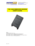
This document is available at HTTP://WWW.FALCOM.DE/ . TANGO Hardware description Version 1.04 TANGO VERSION 1.04 Contents 0 INTRODUCTION ..............................................................4 0.1 0.2 0.3 SCOPE OF THE USER’S GUIDE .......................................................................................................... 5 USED ABBREVIATIONS .................................................................................................................... 6 RELATED DOCUMENTS.................................................................................................................... 6 1 SECURITY .........................................................................7 1.1.1 1.1.2 1.1.3 1.1.4 1.1.5 1.1.6 1.1.7 1.1.8 1.1.9 1.1.10 1.1.11 1.1.12 1.1.13 1.2 GENERAL..................................................................................................................................... 7 EXPOSURE TO RF ENERGY ..................................................................................................... 7 EFFICIENT MODEM OPERATION............................................................................................ 7 ANTENNA CARE AND REPLACEMENT................................................................................. 8 DRIVING ...................................................................................................................................... 8 ELECTRONIC DEVICES............................................................................................................. 8 VEHICLE ELECTRONIC EQUIPMENT .................................................................................... 8 MEDICAL ELECTRONIC EQUIPMENT ................................................................................... 8 AIRCRAFT ................................................................................................................................... 8 CHILDREN ................................................................................................................................... 9 BLASTING AREAS ..................................................................................................................... 9 POTENTIALLY EXPLOSIVE ATMOSPHERES........................................................................ 9 NON-IONISING RADIATION .................................................................................................... 9 SAFETY STANDARDS ..................................................................................................................... 10 2 GENERAL CHARACTERISTICS.................................11 2.1.1 2.1.2 2.1.3 2.1.4 General ........................................................................................................................................ 11 Electrical...................................................................................................................................... 11 Physical........................................................................................................................................ 11 Basic Features.............................................................................................................................. 11 2.1.4.1 2.1.4.2 2.1.4.3 2.1.4.4 2.1.4.5 2.1.4.6 Telephony ..................................................................................................................................................... 11 Short Message Service (GSM and GPRS mode)........................................................................................... 12 GSM circuit Data Features .......................................................................................................................... 12 GPRS Packet Data Features ........................................................................................................................ 12 GSM Supplementary services ....................................................................................................................... 12 Other features............................................................................................................................................... 12 2.1.5 2.1.6 Interfaces ..................................................................................................................................... 13 Power consumption ..................................................................................................................... 13 2.1.6.1 2.1.6.2 2.1.6.3 TANGO-900/1800-X..................................................................................................................................... 13 TANGO-900/1800-X-G2 .............................................................................................................................. 14 TANGO-900/1800-X –G10........................................................................................................................... 15 2.1.7 2.1.8 Temperature Range...................................................................................................................... 15 RF characteristics......................................................................................................................... 16 2.1.8.1 2.1.8.2 2.1.8.3 Receiver........................................................................................................................................................ 16 Transmitter................................................................................................................................................... 16 Determining the External Equipment Type .................................................................................................. 16 2.1.9 Interfaces ..................................................................................................................................... 17 2.1.9.1 2.1.9.2 2.1.9.3 2.1.9.4 2.1.9.5 2.1.9.6 Interface A (4-pin connector) ....................................................................................................................... 18 Interface B (9-pin D-SUB connector)........................................................................................................... 19 Interface C (8-pin RJ45 connector).............................................................................................................. 20 Interface D (antenna interface) .................................................................................................................... 21 Interface E (SIM interface)........................................................................................................................... 21 Interface F (Optical indicator interface)...................................................................................................... 22 2.2 2.2.1 2.2.2 2.2.3 FUNCTIONAL DESCRIPTION ........................................................................................................... 22 Ignition line.................................................................................................................................. 23 Serial handling............................................................................................................................. 23 Reset configuration...................................................................................................................... 24 3 GENERAL GUIDELINES FOR THE USE OF THE TANGO .............................................................................25 3.1 3.2 GETTING STARTED ........................................................................................................................ 25 HARDWARE & SOFTWARE REQUIREMENTS ................................................................................... 25 This confidential document is the property of FALCOM GmbH and may not be copied or circulated without permission. Page 1 TANGO VERSION 1.04 3.2.1 Minimum hardware interface to get started ................................................................................. 25 3.2.1.1 3.2.1.2 3.2.1.3 3.2.1.4 3.2.1.5 3.2.1.6 Connecting the external antenna (SMB type) ............................................................................................... 25 Installing the SIM card................................................................................................................................. 26 Connecting the Modem to external device cable .......................................................................................... 26 Connecting the DC power supply................................................................................................................. 27 Mounting the terminal.................................................................................................................................. 28 Placing the terminal ..................................................................................................................................... 28 3.2.2 Terminal emulator setup .............................................................................................................. 29 3.2.2.1 Checking the Modem (using Microsoft Windows™ Hyper Terminal as example) ....................................... 29 3.2.3 3.2.4 Getting started to GPRS Network................................................................................................ 31 Adding a Modem ......................................................................................................................... 31 3.2.4.1 Making a dial-up networking ....................................................................................................................... 34 3.2.5 3.3 3.4 3.4.1 Making a dial-up networking....................................................................................................... 35 COMMUNICATIONS SOFTWARE ..................................................................................................... 40 BASIC OPERATION ........................................................................................................................ 41 Troubleshooting........................................................................................................................... 42 4 HOUSING .........................................................................44 4.1 HOUSING OF CRADLE .................................................................................................................... 45 5 APPENDIX .......................................................................46 5.1 5.1.1 5.2 5.2.1 5.2.2 5.3 5.4 RECOMMENDATIONS FOR POWER SUPPLY ..................................................................................... 46 External cable for power supply .................................................................................................. 46 POSSIBLE EXTERNAL DEVICES: ..................................................................................................... 47 Operation of the active receiver................................................................................................... 48 Interface ....................................................................................................................................... 48 POSSIBLE EXTERNAL ANTENNA .................................................................................................... 49 POSSIBLE EXTERNAL HEADSET ..................................................................................................... 49 Version history: Version number 1.00 1.01 Author F. Beqiri F. Beqiri 1.02 F. Beqiri 1.03 F. Beqiri 1.04 F. Beqiri Changes Initial version Average current in GPRS Mode added. New chapters added (3.2.1.5, 3.2.1.6 and 3.3) New sections added ( ) Housing of cradle (figure 42) optimize. Chapter “Firmware update” removed. Table 1 updated. Determination for DTE or DCE connection (Chapter 2.1.8.3) added. This confidential document is the property of FALCOM GmbH and may not be copied or circulated without permission. Page 2 TANGO VERSION 1.04 Cautions Information furnished herein by FALCOM are accurate and reliable. However, no responsibility is assumed for its use. Please read carefully the safety precautions. If you have any technical questions regarding this document or the product described in it, please contact your distributor. General information about FALCOM and its range of products is available at the following internet address: http://www.falcom.de/ Trademarks Some mentioned products are registered trademarks of their respective companies. Copyright The TANGO user’s guide is copyrighted by FALCOM GmbH with all rights reserved. No part of this user’s guide may be produced in any form without the prior written permission of FALCOM GmbH. FALCOM GmbH. No patent liability is assumed with respect to the use of the information contained herein. This confidential document is the property of FALCOM GmbH and may not be copied or circulated without permission. Page 3 TANGO VERSION 1.04 0 Introduction This manual is focussed on the GSM and GSM/GPRS data solutions of the TANGO series from FALCOM GmbH. TANGO as a Plug-and-Play Dual Band GSM/GPRS device with an integrated SIM card holder, an external antenna connector and standard connector interfaces, provide a quick and easy way to plug in GSM and GPRS functionality to systems and terminals. It can be directly connected via RS232 interface to the serial port of a desktop or notebook computer. A standard SIM card can be inserted in the integrated card holder. The modem can send and receive data by GSM and GPRS network. It supports SMS and Fax as well as voice calls. The TANGO can be easily controlled by using AT command for all kinds of operations. Available in dual-band configurations, this full type approved integrated modem constitutes a self contained, fully integrated implementation of the GSM/GPRS standard. TANGO supports GPRS Class B, class 2 (making download at speeds up to 28.8 kbps) as well as Class B, class 10 (making download at speeds up to 56 kbps). About GPRS: GPRS is standard for General Packet Radio Service that is an add-on to the GSM (Global System for Mobile Communications) cellular network a type of network used to provide cellular phone service. The TANGO Modem provides reliable data connections to GPRS 900 MHz and 1800 MHz as well as to GPRS 850 MHz and 1900 MHz networks. When in regions where GPRS is not available, user can still access their important information with GSM 14.4 kbps data connections. Table below shows the different versions of the TANGO series. DEVICE DISCRIPTION AVAILABILITY TANGO-900/1800-1 GSM only, SMB-male antenna connector Now TANGO-900/1800-1-G10 GSM/GPRS Class B/multi-slot class 10, SMB-male antenna connector Now TANGO-900/1800-1-G2 GSM/GPRS Class B/multi-slot class 2, SMB-male antenna connector Now TANGO-900/1800-2 GSM only, FME-female antenna connector Now TANGO-900/1800-2-G10 GSM/GPRS Class B/multi-slot class 10, FME-female antenna connector Now TANGO-900/1800-2-G2 GSM/GPRS Class B/multi-slot class 2, FME-female antenna connector Now TANGO-850/1900-1 GSM only, SMB-male antenna connector Available soon This confidential document is the property of FALCOM GmbH and may not be copied or circulated without permission. Page 4 TANGO VERSION 1.04 DEVICE DISCRIPTION AVAILABILITY TANGO-850/1900-1-G10 GSM/GPRS Class B/multi-slot class 10, SMB-male antenna connector Available soon TANGO-850/1900-1-G2 GSM/GPRS Class B/multi-slot class 2, SMB-male antenna connector Available soon TANGO-850/1900-2 GSM only, FME-female antenna connector Available soon TANGO-850/1900-2-G10 GSM/GPRS Class B/multi-slot class 10, FME-female antenna connector Available soon TANGO-850/1900-2-G2 GSM/GPRS Class B/multi-slot class 2, FME-female antenna connector Available soon Table 1: TANGO series. Users are advised to quickly proceed to the “Security” chapter and read the hints carefully. 0.1 Scope of the user’s guide This document describes the hardware interface and the technical specifications of the TANGO modem. This product is based on a Dual Band GSM/GPRS engine: every integrated modem referenced TANGO-900/1800 includes a GSM/GPRS 900/1800 MHz module and every integrated modem referenced TANGO-850/1900 includes a GSM/GPRS 850/1900 MHz module. These two dual-band modems have the same specifications unless otherwise specified. As far as network operation is concerned, the TANGO has two versions. The first one is only GSM and the second one is GSM/GPRS modem. The GSM and GSM/GPRS versions have the same specifications unless otherwise specified. This confidential document is the property of FALCOM GmbH and may not be copied or circulated without permission. Page 5 TANGO VERSION 1.04 0.2 Used abbreviations Abbreviation Description ETSI European Telecommunications Standards Institute GSM Global System for Mobile communications IMEI International Mobile station Equipment Identity ME Mobile Equipment GPRS General Packet Radio Service PLMN Public Land Mobile Network PIN Personal Identification Number PUK Personal Unblocking Key RP Receive Protocol RXQUAL Received Signal Quality SIM Subscriber Identity Module SMS Short Message Service SMS/PP Short Message Service/Point-to-Point TA Terminal Adapter TE Terminal Equipment TP Transmit Protocol 0.3 Related documents • ETSI GSM 07.05 “Use of Data Terminal Equipment - Data Circuit terminating Equipment interface for Short Message Service and Cell Broadcast Service“ • ETSI GSM 07.07 “AT command set for GSM Mobile Equipment” • ITU-T V.25ter “Serial asynchronous automatic dialling and control” This confidential document is the property of FALCOM GmbH and may not be copied or circulated without permission. Page 6 TANGO VERSION 1.04 1 Security IMPORTANT FOR THE EFFICIENT AND SAFE OPERATION OF YOUR GSM/GPRS MODEM READ THIS INFORMATION BEFORE USE ! Your GSM or GSM/GPRS modem is one of the most exciting and innovative electronic products ever developed. With it you can stay in contact with your office, your home, emergency services, and others, wherever service is provided. 1.1.1 GENERAL Your modem utilises the GSM standard for cellular technology. GSM is a newer radio frequency (« RF ») technology than the current FM technology that has been used for radio communications for decades. The GSM standard has been established for use in the European community and elsewhere. Your modem is actually a low power radio transmitter and receiver. It sends out and receives radio frequency energy. When you use Your modem, the cellular system handling your calls controls both the radio frequency and the power level of your cellular modem. 1.1.2 EXPOSURE TO RF ENERGY There has been some public concern about possible health effects of using GSM or GSM/GPRS modem. Although research on health effects from RF energy has focused for many years on the current RF technology, scientists have begun research regarding newer radio technologies, such as GSM. After existing research had been reviewed, and after compliance to all applicable safety standards had been tested, it has been concluded that the product is fit for use. If you are concerned about exposure to RF energy there are things you can do to minimise exposure. Obviously, limiting the duration of your calls will reduce your exposure to RF energy. In addition, you can reduce RF exposure by operating your cellular modem efficiently by following the below guidelines. 1.1.3 EFFICIENT MODEM OPERATION For Your modem to operate at the lowest power level, consistent with satisfactory call quality: If Your modem has an extendible antenna, extend it fully. Some models allow you to place a call with the antenna retracted. However Your modem operates more efficiently with the antenna fully extended. Do not hold the antenna when the modem is « IN USE ». Holding the antenna affects call quality and may cause the modem to operate at a higher power level than needed. This confidential document is the property of FALCOM GmbH and may not be copied or circulated without permission. Page 7 TANGO 1.1.4 VERSION 1.04 ANTENNA CARE AND REPLACEMENT Do not use the modem with a damaged antenna. If a damaged antenna comes into contact with the skin, a minor burn may result. Replace a damaged antenna immediately. Consult your manual to see if you may change the antenna yourself. If so, use only a manufacturer-approved antenna. Otherwise, have your antenna repaired by a qualified technician. Use only the supplied or approved antenna. Unauthorised antennas, modifications or attachments could damage the modem and may contravene local RF emission regulations or invalidate type approval. 1.1.5 DRIVING Check the laws and regulations on the use of cellular devices in the area where you drive. Always obey them. Also, when using Your modem while driving, please: give full attention to driving, pull off the road and park before making or answering a call if driving conditions so require. When applications are prepared for mobile use they should fulfil road-safety instructions of the current law! 1.1.6 ELECTRONIC DEVICES Most electronic equipment, for example in hospitals and motor vehicles is shielded from RF energy. However RF energy may affect some malfunctioning or improperly shielded electronic equipment. 1.1.7 VEHICLE ELECTRONIC EQUIPMENT Check your vehicle manufacturer’s representative to determine if any on board electronic equipment is adequately shielded from RF energy. 1.1.8 MEDICAL ELECTRONIC EQUIPMENT Consult the manufacturer of any personal medical devices (such as pacemakers, hearing aids, etc...) to determine if they are adequately shielded from external RF energy. Turn Your modem OFF in health care facilities when any regulations posted in the area instruct you to do so. Hospitals or health care facilities may be using RF monitoring equipment. 1.1.9 AIRCRAFT Turn Your modem OFF before boarding any aircraft. Use it on the ground only with crew permission. Do not use in the air. To prevent possible interference with aircraft systems, Federal Aviation Administration (FAA) regulations require you to have permission from a crew member to use Your modem while the plane is on the ground. To prevent interference with cellular systems, local RF regulations prohibit using Your modem whilst airborne. This confidential document is the property of FALCOM GmbH and may not be copied or circulated without permission. Page 8 TANGO VERSION 1.04 1.1.10 CHILDREN Do not allow children to play with Your modem. It is not a toy. Children could hurt themselves or others (by poking themselves or others in the eye with the antenna, for example). Children could damage the modem, or make calls that increase Your modem bills. 1.1.11 BLASTING AREAS To avoid interfering with blasting operations, turn your unit OFF when in a « blasting area » or in areas posted : « turn off two-way radio ». Construction crew often use remote control RF devices to set off explosives. 1.1.12 POTENTIALLY EXPLOSIVE ATMOSPHERES Turn Your modem OFF when in any area with a potentially explosive atmosphere. It is rare, but Your modem or its accessories could generate sparks. Sparks in such areas could cause an explosion or fire resulting in bodily injury or even death. Areas with a potentially explosive atmosphere are often, but not always, clearly marked. They include fuelling areas such as petrol stations ; below decks on boats ; fuel or chemical transfer or storage facilities ; and areas where the air contains chemicals or particles, such as grain, dust, or metal powders. Do not transport or store flammable gas, liquid, or explosives, in the compartment of your vehicle which contains Your modem or accessories. Before using Your modem in a vehicle powered by liquefied petroleum gas (such as propane or butane) ensure that the vehicle complies with the relevant fire and safety regulations of the country in which the vehicle is to be used. 1.1.13 NON-IONISING RADIATION As with other mobile radio transmitting equipment, users are advised that for satisfactory operation and for the safety of personnel, it is recommended that no part of the human body be allowed to come too close to the antenna during operation of the equipment. The radio equipment shall be connected to the antenna via a non-radiating 50Ohm coaxial cable. The antenna shall be mounted in such a position that no part of the human body will normally rest close to any part of the antenna. It is also recommended to use the equipment not close to medical devices as for example hearing aids and pacemakers. This confidential document is the property of FALCOM GmbH and may not be copied or circulated without permission. Page 9 TANGO VERSION 1.04 1.2 Safety standards THIS CELLULAR MODEM COMPLIES WITH ALL APPLICABLE RF SAFETY STANDARDS. This cellular modem meets the standards and recommendations for the protection of public exposure to RF electromagnetic energy established by governmental bodies and other qualified organisations, such as the following : - Directives of the European Community, Directorate General V in Matters of Radio Frequency Electromagnetic Energy. This confidential document is the property of FALCOM GmbH and may not be copied or circulated without permission. Page 10 TANGO VERSION 1.04 2 General characteristics 2.1.1 General • • • • • • • • • • • 2.1.2 Dual Band GSM/GPRS modem E-GSM 900/1800 MHz or E-GSM 850/1900 MHz Class 4 (2W at 850/900 MHz) Class 1 (1W at 1800/1900 MHz) Small size and low power consumption Voice, SMS Fax and data transmission without extra hardware Tricodec (FR/EFR/HR) Internal 3V SIM interface Easy remote control by AT commands for dedicated applications Fully Type Approved according to GSM Phase 2+ specifications Fully shielded and ready-to-use Electrical Power supply: 2.1.3 10.8 ... 31.2 V DC (absolute maximum ratings) for more details refer to the chapter 2.1.6 “Power consumption” (table 2 to 7) Physical Absolute maximum dimension: 115 mm x 52 mm x 26.6 mm (L x B x H) Weight: 82.6 g (with SMB connector) 88.0 g (with FME connector) Absolute maximum dimension of cradle: 119.4mm x 66.7mm x 31.8mm(L x B x H) Weight of cradle: 21 gr Casing: Complete shielding (Chromium-plate ABS) Mounting: through 2 screw holes on the cradle Operating temperature range: -20°C to + 55°C Functional temperature: -20°C to + 70°C Storage temperature: -30°C to + 85°C 2.1.4 Basic Features 2.1.4.1 Telephony • • • Telephony (TCH/FS) & Emergency calls Full Rate, Enhanced Full Rate and Half Rate Dual Tone Multi Frequency function (DTMF) This confidential document is the property of FALCOM GmbH and may not be copied or circulated without permission. Page 11 TANGO VERSION 1.04 2.1.4.2 Short Message Service (GSM and GPRS mode) • • • Text and PDU Point to point MT & MO SMS Cell Broadcast 2.1.4.3 GSM circuit Data Features • • • • Data circuit asynchronous, transparent and non transparent up to 14,400 bits/s Automatic fax group 3 (Class 1 & 2) Alternate speech and fax MNP2, V.42bis 2.1.4.4 GPRS Packet Data Features • • • GPRS Class B Class 2 (up to 28.8 kbps) or GPRS Class B Class 10 (up to 56 kbps) Coding Schemes: CS1 to CS4 Compliant with SMG31bis 2.1.4.5 GSM Supplementary services • • • • • • • • • Call Forwarding Call Barring Multiparty Call Waiting and Call Hold Calling Line Identity Advice of Charge USSD Closed User Group Explicit Call Transfer 2.1.4.6 Other features • • • • • • ME+SIM phone book management Fixed Dialling Number SIM Toolkit Class 2 SIM, network and service provider locks Real Time Clock UCS2 character set management This confidential document is the property of FALCOM GmbH and may not be copied or circulated without permission. Page 12 TANGO 2.1.5 VERSION 1.04 Interfaces Single antenna interface: SMB or FME antenna connector. Internal SIM interface: 3V only For Data Operation: RS-232C serial link Remote control by AT commands (GSM 07.07 and 07.05) Serial baud rate from 300 to 115,200 bits/s Autobauding (300 up to 38400 bits/s) Audio: RJ45 serial link (microphone and speaker) 2.1.6 Power consumption 2.1.6.1 TANGO-900/1800-X Average current (in mA at 12 VDC): GSM 900 1800 GSM band 31 31 in idle mode (base station sends at -85 dBm) 125 96 in transmit mode at power level 7/3 162 118 in transmit mode at power level 5/0 (maximum) Serial interface is applied and working. 25 mA (off) IF MODEM IS SWITCHED OFF (BY AT+CPOF OR AT+CFUN=0), BUT POWER IS STILL SUPPLIED. (Serial interface is applied and working) Table 2: Power consumption at 12 VDC. Average current (in mA at 24 VDC): 900 1800 GSM GSM band 18 18 in idle mode (base station sends at -85 dBm) 67 50 in transmit mode at power level 7/3 88 64 in transmit mode at power level 5/0 (maximum) Serial interface is applied and working. Table 3: Power consumption at 24 VDC. This confidential document is the property of FALCOM GmbH and may not be copied or circulated without permission. Page 13 TANGO VERSION 1.04 2.1.6.2 TANGO-900/1800-X-G2 Average current (in mA at 12 VDC): GSM 900 1800 GSM band 31 31 in idle mode (base station sends at -85 dBm) 123 103 in transmit mode at power level 7/3 158 127 in transmit mode at power level 5/0 (maximum) Serial interface is applied and working. GPRS 160.36 mA in transmit mode at power level 5 25 mA (off) IF MODEM IS SWITCHED OFF (BY AT+CPOF OR AT+CFUN=0), BUT POWER IS STILL SUPPLIED. (Serial interface is applied and working) Table 4: Power consumption at 12 VDC. Average current (in mA at 24 VDC): 900 1800 GSM GSM band 16 16 in idle mode (base station sends at -85 dBm) 67 54 in transmit mode at power level 7/3 84 68 in transmit mode at power level 5/0 (maximum) Serial interface is applied and working. GPRS 84.46 mA Table 5: in transmit mode at power level 5 Power consumption at 24 VDC. This confidential document is the property of FALCOM GmbH and may not be copied or circulated without permission. Page 14 TANGO VERSION 1.04 2.1.6.3 TANGO-900/1800-X –G10 Average current (in mA at 12 VDC): GSM 900 1800 GSM band 32 32 in idle mode (base station sends at -85 dBm) 118 110 in transmit mode at power level 7/3 147 138 in transmit mode at power level 5/0 (maximum) Serial interface is applied and working. GPRS 257.06 mA in transmit mode at power level 5 25 mA (off) IF MODEM IS SWITCHED OFF (BY AT+CPOF OR AT+CFUN=0), BUT POWER IS STILL SUPPLIED. (Serial interface is applied and working) Table 6: Power consumption at 12 VDC. Average current (in mA at 24 VDC): 900 1800 GSM GSM band 17 17 in idle mode (base station sends at -85 dBm) 62 57 in transmit mode at power level 7/3 78 74 in transmit mode at power level 5/0 (maximum) Serial interface is applied and working. GPRS 132.22 mA Table 7: 2.1.7 in transmit mode at power level 5 Power consumption at 24 VDC. Temperature Range Operating temperature range: Functional temperature: Storage temperature: -20°C to + 55°C -20°C to + 70°C -30°C to + 85°C This confidential document is the property of FALCOM GmbH and may not be copied or circulated without permission. Page 15 TANGO 2.1.8 VERSION 1.04 RF characteristics 2.1.8.1 Receiver EGSM Sensitivity DCS Sensitivity Selectivity @ 200 kHz Selectivity @ 400 kHz Dynamic range Intermodulation Co-channel rejection : : : : : : : <-104 dBm <-100 dBm > + 9 dBc > +41 dBc 62 dB >- 43 dBm > = 9 dBc : : : : : : : : : : : 33dBm ± 2dB 30dBm ± 2dB 5dBm ± 5dB 0dBm ± 5dB < -30dBm < -30dBm < -67dBm < -79dBm < -71dBm < 5 ° RMS +/- 0.1ppm max 2.1.8.2 Transmitter Maximum output power (EGSM) Maximum output power (DCS) Minimum output power (EGSM) Minimum output power (DCS) H2 level H3 level Noise in 925 - 935 MHz Noise in 935 - 960 MHz Noise in 1805 - 1880 MHz Phase error at peak power Frequency error 2.1.8.3 Determining the External Equipment Type Before you connect the DB9 serial port connectors on the aforementioned terminals (DCE units) to external equipment, you need to determine if the external hardware serial ports are configured as DTE or DCE. The terms DTE (Data Terminal Equipment) and DCE (Data Communications Equipment) are typically used to describe serial ports on devices. Computers (PCs) generally use DTE connectors and communication devices such as modems and DSU/CSU devices generally use DCE connectors. As a general rule, DTE ports connect to DCE ports via straight through pinned cables. In other words, a DTE port never connects directly to another DTE port. Similarly, a DCE port never connects directly to another DCE port. The signalling definitions were written from the perspective of the DTE device; therefore, a Receive Data signal becomes an input to DTE but an output from DCE. All TANGO series are designed for use as a DCE unit. Based on the aforementioned conventions for DCE-DTE connections it communicates with the customer application (DTE) using the following signals: This confidential document is the property of FALCOM GmbH and may not be copied or circulated without permission. Page 16 TANGO VERSION 1.04 TANGO Terminal (DCE) to Application (DTE) TxD ◄----------------------- TXD RxD -----------------------► RXD RTS ◄----------------------- RTS CTS -----------------------► CTS DTR ◄----------------------- DTR DSR -----------------------► DSR DCD -----------------------► DCD RING -----------------------► RING Table 8: The signaling definitions between DTE and DCE. 2.1.9 Interfaces Interface specifications Interface A 4-pin Micro-Fit™ 3.0 Molex Part number: 43045-0406 (Female) Interface B Standard RS232 serial interface Interface C Audio 8-pin RJ45, RS232 (Rx, Tx) serial interface Interface D GSM antenna with SMB or FME antenna connector. Interface E Interface F SIM card reader for small SIM cards (3V) LED’s for status indication Table 9: Interface specifications of the Modem This confidential document is the property of FALCOM GmbH and may not be copied or circulated without permission. Page 17 TANGO VERSION 1.04 Figure 1: view of TANGO interfaces. 2.1.9.1 Interface A (4-pin connector) Figure 2: Pin out of 4-pin power supply connector (interface A) Power input: 10,8....31,2 V DC Pin number Name Functions 1 GND DC power negative input 2 Mute Do not connect 3 IGN Ignition (connected to positive DC power) 4 POWER (+Vin) DC power positive input Table 9: Description of modem power connector A cable, included in the package shall be used for power supply connection. For more deteils see Appendix chapters 5.1 and 5.1.1. This confidential document is the property of FALCOM GmbH and may not be copied or circulated without permission. Page 18 TANGO VERSION 1.04 2.1.9.2 Interface B (9-pin D-SUB connector) Interface B has the highest priority connection to control the TANGO modem. This one has a standard D-SUB-male serial connector. RS232 9 pin D-Sub to DIN 41652 +/-12V RX, TX, RTS, CTS, DTR, DSR, DCD, RI 300...115200 Baud rates for serial link (2400...19200 with auto-bauding) Interface B (DB9 connector) has the following layout. Figure 3: RS232 pin-out (interface B) Pin Description Direction 1 DCD ↔ Data Carrier Detect OUT 2 RxD ↔ Received Data OUT 3 TxD ↔ Transmitted Data IN 4 DTR ↔ Data Terminal Ready IN 5 GND ↔ Signal Ground - 6 DSR ↔ Data Set Ready OUT 7 RTS ↔ Request To Send IN 8 CTS ↔ Clear To Send OUT 9 RI ↔ Ring Indicator OUT Table 10: Pin assignment of the standard RS232 connector This confidential document is the property of FALCOM GmbH and may not be copied or circulated without permission. Page 19 TANGO VERSION 1.04 2.1.9.3 Interface C (8-pin RJ45 connector) The TANGO modem provides this interface (RJ45) for serial and audio connection. You can use a RJ45 serial cable to connect the modem’s RJ45 connector (Interface C) to external controller/computer (without HW handshake). If TANGO modem has been connected through interface B, interface C is automatically deactivated (Rx, Tx). In this case, only 4 pins are available (MIC[+,-] and SPK[+,-]). So a headset can be connected (see Appendix chapter 5.4 headset’s characteristic). This interface supports also a connection to an external device such as active headset HA-88, which provided by Falcom GmbH, for communication call. For more details about HA-88 see chapter 5.2 “Possible external devices”. Figure 4: Audio interface pin-out (interface C) Pin Description Direction 1 Power output 10V ± 5% 150mA OUT 2 TxD ↔ Transmitted Data IN 3 RxD ↔ Received Data OUT 4 Ground - 5 SPK+ OUT 6 SPK- OUT 7 MIC+ IN 8 MIC- IN Table 11: Pin assignment of RJ45 This confidential document is the property of FALCOM GmbH and may not be copied or circulated without permission. Page 20 TANGO VERSION 1.04 2.1.9.4 Interface D (antenna interface) There are two versions as far as antenna interface is concerned of the TANGO modem. The specifications and functions of the modems are the same. The difference between both equipments can be recognised by looking at the GSM antenna on the left side of the modems: the first one supports an antenna with SMB connector interface (Figure 5.a); the second one supports an antenna with FME connector interface (Figure 5.b). The Length of antenna cable integrated on the versions of TANGO (–xxx/xxx-2 (-xx) see table 1 ) is 23.3 cm. Figure 5.a: TANGO modem with SMB antenna connector (all versions TANGO – xxx/xxx-1 (-xx) see table 1) Figure 5.b: TANGO modem with FME antenna connector (all versions TANGO –xxx/xxx-2 (-xx) see table 1) 2.1.9.5 Interface E (SIM interface) The SIM interface controls a 3V SIM Card. This interface is fully compliant with GSM 11.11 recommendations concerning SIM functions. Figure 6: SIM interface (interface E) This confidential document is the property of FALCOM GmbH and may not be copied or circulated without permission. Page 21 TANGO VERSION 1.04 2.1.9.6 Interface F (Optical indicator interface) The actual state of the TANGO is displayed by two LED’s on interface F of the unit (for more details see chapter 2.2 Functional description). Figure 7: Status indicator of modem 2.2 Functional description The GSM/GPRS modem TANGO is a mobile station for the transmission of voice, data and fax calls as well as SMS in GSM/GPRS networks. The GSM/GPRS modem TANGO consists of the following components: • • • • GSM/GPRS transceiver Power supply unit Serial link (V.24) for data transmission and control GPRS Class B, class 2 or class 10. If the GSM/GPRS modem TANGO is registered in the network, it acts just like a regular fax/data modem. To control the GSM modem there is an advanced set of AT-commands according to GSM ETSI 07.07 and 07.05 implemented. The two LED’s on the top of Interface C are showing the state of TANGO. The yellow LED signals the actual connection of the modem (interface B or C) and the green LED signals power connection, GSM/GPRS network, a “RESET” function and “SOFT-ON ” procedure. The actual state of the TANGO is displayed by two LED’s at the connector on the top of interface C of the unit. • • Green, Yellow off: Green light: • • • • Green flashes: Green flashes quickly: Yellow off: Yellow light: Modem is switched off. Power on, not registered in the network. Power on, registered in the network. Call in progress. Power off or interface C in use. Power on, interface B in use or both interfaces (B & C) are not connected. This confidential document is the property of FALCOM GmbH and may not be copied or circulated without permission. Page 22 TANGO 2.2.1 VERSION 1.04 Ignition line The Ignition Line on Interface A uses an internal processor to control the timing of the “SOFT-ON“ procedure of the internal GSM modem. To switch the modem ON the Ignition Line has to be connected to a high voltage level of (10,8V ... 31,2V). The green LED on interface C shows the progress of the “SOFT-ON“ procedure (green indicator light). Enter PIN Number of the inserted SIM card (if required). After a few seconds it will go flashing slowly (that’s mean the registration into the network is successfully). To switch the modem off the commands AT+CPOF or AT+CFUN=0 (see AT commands manual) has to be issued. To switch the modem on again see above. 2.2.2 Serial handling The GSM/GPRS modem TANGO allows control of the GSM/GPRS modem over the interface B or Interface C. The interface B is a implementation of a serial interface corresponding EIA-RS232-C. See table below for details: CCITT V24 Pin Description Direction 102 5 Signal Ground (GND) 103 3 Transmitted Data (TxD). The DTE uses the TxD line to send data to the interface for transmission over the Modem. IN 104 2 Received Data (RxD). The interface uses the RxD to send data received from the Modem to the DTE. OUT 105 7 Request To Send (RTS) IN 106 8 Clear To Send (CTS) OUT 107 6 Data Set Ready (DSR) OUT 108 4 Data Terminal Ready (DTR) IN 109 1 Data Carrier Detect (DCD) OUT 125 9 Ring Indicator (RI) OUT Table 12: R232 9-pin description Both interface B and C are not independent usable. The interface B has the highest priority. If you don’t want to use the interface B you must deactivate the signals RTS (or remove connection). With the interface C you have the audio and control functionality on one interface. This confidential document is the property of FALCOM GmbH and may not be copied or circulated without permission. Page 23 TANGO VERSION 1.04 See table for connections: Pin Description Direction 1 Power output 10V ± 5% 150mA OUT 2 Received Data (RxD) IN 3 Transmitted Data (TxD) OUT 4 Ground 5 SPK+ OUT 6 SPK- OUT 7 MIC+ IN 8 MIC- IN Table 13: Pin description fo RJ45 2.2.3 Reset configuration In case of malfunction the GSM/GPRS modem TANGO offers various RESET possibilities. For a RESET of the GSM/GPRS modem please use the following way: 9 If the Ignition Line is removed from the high voltage level (10,8V31,2V), please, supply it to high voltage level (10,8V-31,2V). 9 “Break” on serial interfaces B or C (Transmit Data [TxD] set to “LOW” for >100ms). If the GSM software is still running, while the user feels the need to reset the modem, AT+CFUN=1,1 could be used. This will de-register the modem from the network and bring it into the state before the PIN has been entered. This confidential document is the property of FALCOM GmbH and may not be copied or circulated without permission. Page 24 TANGO VERSION 1.04 3 General guidelines for the use of the TANGO 3.1 Getting started 3.2 Hardware & software requirements 9 9 9 9 9 A valid SIM card. Free compatible COM serial port Pentium 90 or higher. System memory: At least 64MB Operating system: Windows® 95, 98/Me/2000/XP For data, Web and email applications. 9 Dial-up networking configured to your ISP (Internet Service Provider). 3.2.1 Minimum hardware interface to get started As a minimum, it is necessary to connect the following interfaces to operate the TANGO properly: 3.2.1.1 Connecting the external antenna (SMB type) If you are using a Dual-Band GSM antenna (see chapter 5.3 Possible external antenna), connect the SMB-female antenna connector to the SMBmale modem connector. For others external antenna, please refer to manuals of manufacture’s GSM antenna. Make sure the external antenna is for the GSM 900/1800 or 850/1900 frequency with impedance of 50Ω, and also connector is secured tightly. Note: Please use antenna designed for GSM 900/1800 or 850/1900 MHz operation. Incorrect antenna will affect communication and even damage the modem. Figure 8: Connect the GSM antenna This confidential document is the property of FALCOM GmbH and may not be copied or circulated without permission. Page 25 TANGO VERSION 1.04 3.2.1.2 Installing the SIM card Keep all miniature SIM cards out small children’s reach. The SIM card and its contacts can be damaged by scratches or bending, so be careful when handling, inserting or removing the SIM card. Open the cover cap on the underside of the modem, push the SIM card holder forwards on the inscription “PUSH ▲ OPEN”, flap the holder upwards and insert the SIM card into the SIM card holder and push it down (ensure that the bevelled corner is on the top right and the golden contact area is facing downwards). Make sure that the SIM card is fit in the SIM card holder. Push the cap of SIM card holder down until it closed. Close the opening with the cover cap. Figure 9: Open the cover cap. Figure 10: Push the inscription “PUSH ▲ OPEN” to open the SIM card holder. Figure 11: Insert the SIM card. Hints: To remove the SIM card please follow the steps above and remove. Important: Do not insert or remove the SIM card when the device is under power. 3.2.1.3 Connecting the Modem to external device cable You can use the optional RS232 serial cable to connect the D-SUB connector (Interface B) to external controller/computer. Connect the 9-pin Sub D-female serial cable to COM1 or COM2 on your PC (or to another free serial interface port), as shown in Figure 12.a. Connect the other end of the 9-pin Sub D-male serial cable to the 9-pin serial interface port on the TANGO modem, as shown in Figure 12.b. This confidential document is the property of FALCOM GmbH and may not be copied or circulated without permission. Page 26 TANGO VERSION 1.04 Figure 12.a: Connect 9pin serial to PC Figure 12.b: Connect 9pin serial to modem. 3.2.1.4 Connecting the DC power supply Connect the open ending of the power supply cable to a power adapter (10.8...31.2 VDC). Refer to the following table for power supply requirement. Power Supply Requirement: Parameters Min Typical Max Unit Supply voltage 10.8 12 31.2 V DC Table 14: Required power supply Connect the power supply cable with 4-pin Micro-Fit-male connector to the modem’s 4-pin Micro-Fit-female connector, and supply voltage via the power adapter. The Modem will turn on automatically (“Ignition Line” must be connected to supply voltage). The status indicator (green and yellow) on the top of RJ45-Audio interface will be lit when power on. After a few seconds after you have entered the PIN number (if needed) the green LED will go flashing slowly (that’s mean registration into the network is successfully). Note: Do not used the external cable for power supply without a (car voltage) voltage adapter. Figure 13.a: Connect the DC power supply Figure 13.b: Power supply cable This confidential document is the property of FALCOM GmbH and may not be copied or circulated without permission. Page 27 TANGO VERSION 1.04 3.2.1.5 Mounting the terminal Figure14.a Place the modem on the cradle and firmly fixed. Figure14.b Cable-joiner Place the terminal (if is needed) on the cradle and push it down, make sure that the modem does not move up and down inside the cradle, the cradle is in the sales package. After that, the user have to use the cables-joiner for a firmly fixed (figure 14.a) the modem and the power supply cable. For power supply cable use the small cable-joiner and for modem use one of the length cable-joiner. The dimensions of cable-joiner are 200 x 3.5 mm and 140 x 3.5 mm. Note: If you want to mount the terminal on a wall or vehicle, first attach the cradle to the wall or vehicle as described on the chapter below before placing the terminal on the cradle. 3.2.1.6 Placing the terminal Caution: In order to comply with RF exposure requirements, install the terminal so that a minimum distance of 20 cm can be maintained between the antenna and all persons. If you use an external antenna, install the antenna so that a minimum distance of 20 cm can be maintained between the antenna and all persons, with antenna gain not exceeding 3 dBi. Place the terminal in a proper location, for example on the desk far enough from your PC. It is also possible to install the terminal to a wall or a vehicle: 1. Choose a location far enough from electronic devices so that no interference takes place. 2. Drill appropriate screws through the two indentations on the cradle. 3. After you have secured the cradle to the wall or vehicle, place the terminal as described above in section "Mounting the terminal" Note: All radio transmitting devices send signals which may cause interference in different electronic devices (PC, television etc). To avoid interference, place the terminal far enough from other electronic devices. This confidential document is the property of FALCOM GmbH and may not be copied or circulated without permission. Page 28 TANGO 3.2.2 VERSION 1.04 Terminal emulator setup Here below is an example based on the Windows™ Hyperterminal application (terminal emulator program). The instructions below describe how to use the TANGO Modem with a PC running Windows 2000. 3.2.2.1 Checking the Modem (using Microsoft Windows™ Hyper Terminal as example) a On the first time power-up you can use a terminal software, which makes the communication with modem through a RS232 serial port possible. The following example is using the Hyper Terminal in Windows 2000. Figure 15: Using Microsoft Windows™ Hyper Terminal a On Windows 2000, start the Hyper Terminal program. Assign the name for a new session on the displayed window. Figure 16: Assign the name for a new session This confidential document is the property of FALCOM GmbH and may not be copied or circulated without permission. Page 29 TANGO VERSION 1.04 a Choose the correct COM Port and baud rate settings (9600bps, 8 bit, no parity bit, 1 stop bit). Figure 17: COM Port transmission settings a On the terminal screen, type “AT” to check the “OK” response from the Modem. Figure 18: Check the response from TANGO 9 Now you can configure the TANGO modem according to your requirements and according to the AT-Command set. This confidential document is the property of FALCOM GmbH and may not be copied or circulated without permission. Page 30 TANGO 3.2.3 VERSION 1.04 Getting started to GPRS Network The following instructions are available only for TANGO versions providing GPRS. What is GPRS: 9 GPRS is a complete new part of the existing GSM network. 9 GPRS is packed switched high speed mobile data. 9 GPRS is an efficient approach to upgrade the existing GSM to a packet switched system. 9 GPRS is an important step in direction to mobile internet. What you need? 9 GPRS settings from your network provider APN (name of access point that connects the mobile network to the Internet) Primary and secondary DNS IP header compression IP address (DHCP or static) User name and password ( may be optional) Dial number 9 Modem installation and configuration 9 Dial-Up Network installation and configuration Should the standard 19200 modem not installed, you have to install it, else please turn to the next chapter. The instructions below describe how to use the TANGO Modem with a PC running Windows 2000. 3.2.4 Adding a Modem Click Start button, point to Settings, then click Control Panel. Double click the Modem icon. Figure 19: Add a new Modem. This confidential document is the property of FALCOM GmbH and may not be copied or circulated without permission. Page 31 TANGO VERSION 1.04 If your system have no modem installed it will show the Install New Modem dialog box, otherwise it will show Modem Properties you can then press the Add button. On Install New Modem dialog box, activate the Don’t detect my modem check box and press the Next button. Figure 20: Install new Modem. Select the Standard 19200bps Modem, then press Next. Figure 21: Select the standard modem. Choose the COM port number where the TANGO modem is connected to, then press Next button. Figure 22: Selected ports. This confidential document is the property of FALCOM GmbH and may not be copied or circulated without permission. Page 32 TANGO VERSION 1.04 When you have done with the modem installation, click the Properties button from the modem panel. Figure 23: Installed modem. Set the speed to 115200. Figure 24: Select the maximum port speed. This confidential document is the property of FALCOM GmbH and may not be copied or circulated without permission. Page 33 TANGO VERSION 1.04 To have a connection to the GPRS Network choose the Advanced tab. On the “Extra Settings”, type the APN information here. (Consult your Network Operator for the correct APN settings) Common setting is: AT+CGDCONT=1,”IP”,”INTERNET” e.g T-D1 has the following APN: [AT+CGDCONT=1,”IP”,”internet.t-d1.de”]. Figure 25: GPRS extra initialization command. 3.2.4.1 Making a dial-up networking This brief guide aims at explaining the basic steps for getting started with GPRS to the internet. It supposes you are a bit familiar with GPRS concepts, like network attachment, session or PDP context. This guide is not intended to give full details about how GPRS works, all GPRS-specific AT commands (check out the GPRS AT command manual). The GPRS AT command manual is available on the Falcom’s Website for download: Î www.falcom.de/service/manual/ This confidential document is the property of FALCOM GmbH and may not be copied or circulated without permission. Page 34 TANGO 3.2.5 VERSION 1.04 Making a dial-up networking During the network installation, please follow the on-screen instructions. Click Start button, point to Program, go to Accessories, Communication then click Dial-up Networking. Double click to the Make New Connection icon. Figure 26: Make new connection. The next dialog box click the Next button. Figure 27: Continue the new connection. Activate the Dial-up to private network radio button, then click Next. Figure 28: Network connection type. This confidential document is the property of FALCOM GmbH and may not be copied or circulated without permission. Page 35 TANGO VERSION 1.04 On the Phone Number field enter the phone number, e.g T-D1 has (**99***1#) or (*99#) phone number, then press Next button. Figure 29: Enter the access number for your Network Operator. Enter the name of the dial-up profile (e.g “GPRS). Press the Finish button and you have make a GPRS dial-up profile. Figure 30: Type the name of connection. Now you need to edit some more settings, Right-click just-made GPRS dial-up icon, then click Properties. Figure 31: Some more settings. This confidential document is the property of FALCOM GmbH and may not be copied or circulated without permission. Page 36 TANGO VERSION 1.04 In the opened dialog box, please, select General tab, then press Configure button. The dialog box below is displayed. Please select (activate) the check boxes as shown in the figure below. When the settings are checked then press OK button. Figure 32: Modem configuration. As next select the Networking tab, choose on the Internet Protocol (TCP/IP) component, then press Properties button. Figure 33: Componnent (TCP/IP) configuration. This confidential document is the property of FALCOM GmbH and may not be copied or circulated without permission. Page 37 TANGO VERSION 1.04 The dialog box below is displayed. Activate the Use the following DNS server addresses and type the DNS address of your Operator Network (e.g T-D1 has the following DNS address 193.254.160.001), then press OK button and go back to the GPRS dial-up icon see upon and follow next stepp below. Figure 34: Use the DNS server addresses. Before you start GPRS dial-up make sure that SIM card is inserted and is registered into the GSM network. Registration into the GSM network can be done by entering the PIN number, using the command AT+CPIN=**** via HyperTerminal program. After a successful registration into the GSM network you can make a GPRS dial-up by double click the GPRS icon. Remember to enter User name, Password blank and Dial number on the corresponding input field (or refer to your network operation’s instruction). Figure 35: The dialog box of registration. This confidential document is the property of FALCOM GmbH and may not be copied or circulated without permission. Page 38 TANGO VERSION 1.04 After you have started GPRS dial-up by clicking on the Dial button, the Pre-Dial Terminal Screen will be displayed. See figure here below. Activate by right-click the opened Pre-Dial Terminal Screen screen and type the command AT+CGATT=1 on the black screen input field. The GPRS attach is triggered by using this AT Command. The user can check whether the TANGO is GPRS attached by entering: AT+CGREG? which is the counter-part command of AT+CREG? (GSM attachment status). There are three possible response of TANGO: +CGREG:0,1 means the TANGO is successfully attached. +CGREG:0,0 means the TANGO is trying to attach. +CGREG:0,2 has failed to attach and stopped trying to attach. This occurs approx. within 1-3 min of powering up. Alternatively, the registration status can be retrieved using: AT+CGATT? There are two possible response of TANGO: +CGATT:1 means the MS is successfully attached. +CGATT:0 means the MS is not attached, or has failed to attach. This command is somewhat less accurate than AT+CGREG?. If the TANGO Modem is attached to the GPRS Network the user have to click the Continue button, the other steps have to done. Normally, if everything is going smoothly the TANGO modem within 2 or 3 seconds will be able to build a connection to the Internet. Figure 36: Pre-Dial Terminal Screen. This confidential document is the property of FALCOM GmbH and may not be copied or circulated without permission. Page 39 TANGO VERSION 1.04 The next opened dialog box shows the registering to the GPRS (it takes ca. 2..3 sec.). Figure 37: Message of registering and logging onto the GPRS network The modem is now connected to the GPRS network. Click OK button. Connection to the internet is complete, so the user can start by clicking to the installed internet software. Figure 38: Message of GPRS connection. Right-click to its icon on the taskbar (if present) or in the Network Connection folder to check the status of this connection. To disconnect the connection click the Disconnect Popup menu. Figure 39: Popup menu of Dial-up connection. Now the user can start the installed web browser, see the next section. 3.3 Communications software To connect to the Internet, or to send and receive e-mail or faxes transmit data from your computer, you need the appropriate data and fax communications software. You can use the TANGO modem with most commercially available communications applications, such as Microsoft Exchange, Microsoft Outlook and Netscape Navigator. This confidential document is the property of FALCOM GmbH and may not be copied or circulated without permission. Page 40 TANGO VERSION 1.04 3.4 Basic Operation Followings are example of some AT-commands. Please refer to the AT Command manual for a full discription. The AT Command manual is available on the Falcom’s Website Î www.falcom.de/service/manual NOTE: Issue AT+CMEE=1 to have extended error code (+CME ERROR) Description AT Commands AT+CREG? Network registration checking Receiving an incoming call Modem responce Comments CREG=<mode>,1 Modem registered into the network CREG=<mode>,2 Registration lost, re-registration attempt CREG=<mode>,0 Modem not registration into the network, no registration attempt RING An incoming call is waiting ATA Answer the call OK ATD0123456789; Make a call Do not forget the < ; > at the end for < voice > call OK Communication established CME ERROR: 11 PIN code not entered (with + CMEE=1 mode) CME ERROR: 3 AOC credit exceeded or a communication is already established ATD112; Do not forget the < ; > at the end for < voice > call Make an emergency call OK NO CARRIER Communicatio n loss ATH Hang up OK AT+CPIN=0123 Enter PIN code OK PIN code accepted CME ERROR: 16 Incorrect PIN Code (with + CMEE=1 mode) CME ERROR: 3 PIN already entered (with + CMEE=1 mode) AT&W OK The configuration settings are stored Save parameter This confidential document is the property of FALCOM GmbH and may not be copied or circulated without permission. non-volatile memory Page 41 TANGO VERSION 1.04 Table 15: AT-commands for basic operation 3.4.1 Troubleshooting 1. The modem status indicators do not light: • Check if the modem is connected to a 10.8 .. 31.2 V DC power supply properly. • Check if also the Ignition Line is connected to a 10.8 .. 31.2 V DC power supply properly. • Check if the power connector is properly inserted. 2. The modem does not respond to the terminal program: • Check if the RS232 cable is connected properly. • Check if your program has proper settings. Manufacture settings of the modem are as below: 9600 bps 8 data bits No parity bit 1 stop bit 2 3 GPRS troubleshooting As already mentioned, GPRS is a rather new technology and as a consequence networks and mobiles haven't reached yet the stability level they've been enjoying in GSM. So expect some failures every so often or total failure on some networks! Unfortunately, if you experience a failure (to attach, to activate a session, etc) , there aren't many workarounds you can try. 3.1. Failure to log onto the GPRS network. In such a case, try logging onto the GSM network by issuing: AT+CGCLASS="CC" if MS was in class CG. Registration progress can be checked with: AT+ CREG? See the AT command guide for more information about this command. Basically if after a short while it responds +CREG:0,1 then the MS has successfully completed GSM attachment. As consequence, failure to GPRS attachment is likely due to either: MS firmware fault (contact one of Falcom’s distributors) the cell the MS is camped on does not support GPRS. So far, there isn't any means to check whether a cell supports GPRS. In case GSM registration fails as well, faulty hardware or bad antenna/power connection may be suspected. Check also the SIM card, and be sure to enter PIN code if needed. It's also worth to check the MS's IMEI. 3.2. Failure to activate a session This confidential document is the property of FALCOM GmbH and may not be copied or circulated without permission. Page 42 TANGO VERSION 1.04 If you had entered AT+CGQREQ=1,0,0,3,0,0 then try with AT+CGQREQ=1,0,0,0,0,0 and vice-versa. Also, be sure to enter the APN which is case sensitive. 3.3. Failure to send data after entering an URL The MS is GPRS attached, the session is successfully open, the remote dialup connection is running fine on PC but when I enter an URL in the web browser, nothing seems to happen. So first of all, double click on dialup connection icon from the tray bar and check whether the number of sent bytes increases whenever you enter an URL (and press ENTER). If that number does not increase there is much likely a routing problem coming from the PC. In that case, run the winipcfg tool and check for entries different from 'PPP adapter' from the combo-list. If they are so, select them one by one, and for each one hit 'free' to tell Windows this interface is now down and must done ignored when routing. This confidential document is the property of FALCOM GmbH and may not be copied or circulated without permission. Page 43 TANGO VERSION 1.04 4 Housing Figure 40: Housing of TANGO versions -xxx/xxx-1(-xx). This confidential document is the property of FALCOM GmbH and may not be copied or circulated without permission. Page 44 TANGO VERSION 1.04 4.1 Housing of cradle Figure 41: Housing of cradle. Figure 42: View of cradle. This confidential document is the property of FALCOM GmbH and may not be copied or circulated without permission. Page 45 TANGO VERSION 1.04 5 Appendix 5.1 Recommendations for power supply It is recommended to use the PS002 power supply. Also any other power supply in the range of 10.8 ... 31,2 V DC can be used. It should be able to deliver 2A peak current (for 577µs, rise time 10µs, period 4.615ms, caused by GSM-typical radio transmission), where the ripple voltage of the power supply is recommended to be lower than 300mV. If the power supply is using input-voltages of more than 50 Vrms or 75 V DC it is the response of the applicant to conform with the safety requirements of Telecommunication Terminal Equipment (such as 73/23/EEC). 5.1.1 External cable for power supply Cable designed below, include in the package shall be used for power supply connection. The external power cable is a four-conductor cable with stripped and tinned ends. Connect the white and yellow leads of the external power cable to the positive side of the DC power source. Connect the brown lead of the external power cable to the negative side of the DC power source. The green lead of the external power cable will be left open (not connected). COUTION: Observe polarity when connecting the external power cable. Incorrect input polarity can damage the power adapter. The connector of power cable is a Micro-Fit 3.0 one. Part number: 43025-0400 (male) Figure 43: View of external cable for power supply This confidential document is the property of FALCOM GmbH and may not be copied or circulated without permission. Page 46 TANGO VERSION 1.04 5.2 Possible external devices: There is no active receiver HA-88 included in the deliver package, so you have to purchase it. The order number is: ¾ HA-88 (active receiver) The active handset HA-88 provided by FALCOM GmbH is an accessory for the FALCOM GSM modems such as A2D-1, A2D-3, A2D-3GPS, A3D and TANGO. It provides an additional operating surface similar as like a mobile phone (keypad and display). The active receiver communicates with the TANGO modem through interface C (RJ45) and allows the creation of data connections, display of the network state and network provider. Further there is given the possibility to enter a PIN, interrogate and edit the phonebook and optionally there is a SOS function possible. (You are enabled to establish an emergency call connection by mean of the SOS button also without SIM card. The button is pre-configured with the emergency call number by the manufacturer.) By mean of the comfortable LCD display all running proceedings are shown. NOTE: The active handset HA-88 does not support SMS. The figure below shows the layout of the active receiver HA-88. Figure 44: View of active receiver HA-88 This confidential document is the property of FALCOM GmbH and may not be copied or circulated without permission. Page 47 TANGO 5.2.1 VERSION 1.04 Operation of the active receiver The active receiver HA-88 is plug and play compliant and will be activated by connection of one of the above-mentioned devices. After the initialisation cycle (“turning hour glass”) and registration into the network, it can be used for calling. Figure 45: Designed of main functions to the active receiver HA-88 5.2.2 Interface Figure 46: Pin description of active receiver HA-88 This confidential document is the property of FALCOM GmbH and may not be copied or circulated without permission. Page 48 TANGO VERSION 1.04 5.3 Possible external antenna There are no antenna included in the deliver package, but the antennas designed below can be used for antenna connection. The antenna designed on the figure below are provided by Falcom GmbH. The order numbers are: ¾ ANT-001-M (with FME-male connector) ¾ Dual-Band GSM antenna (with SMB-female connector) ¾ KA08-F (antenna cable with SMB-female and FME-female connectors) The external antenna connector can be a SMB or a FME connector, its dependent on the TANGO version (on all versions of TANGO with the following string TANGO xxx/xxx-1(-xx) using a SMB-male antenna connector and other versions TANGO xxx/xxx-2(-xx)using a FMEfemale antenna connector see table 1). The TANGO modem with SMB connector incorporates a 'Snap On' latching action in order to make the connection easier with an excellent RF performance. An additional advantage is its small physical size. Figures (47.a and 47.b) below shows the possibilities of external GSM/GPRS antennas. If your TANGO modem provides an external SMB connector on the antenna interface both of the designed below GSM/GPRS antennas can be used. In case of using the ANT-001-M with FME connector, FALCOM GmbH provides a special adapter cable between the TANGO and FME antenna connector. The FALCOM type code of this adapter cable is KA08F. Figure (47.a) below shows an external GSM/GPRS antenna with FME connector (ANT-001-M). If your TANGO modem provides an external FME connector on the antenna interface only a GSM/GPRS antenna with FME connector (ANT-001-M) can be used. Figure 47.a: ANT-001-M with FME-male connector and KA08F with SMB-female and FME-female connector. Figure 47.b: Dual-Band GSM antenna with SMB-female connector 5.4 Possible external headset A different microphone inputs and a different speaker outputs are supported by the TANGO modem, so an external headset interface through the RJ45 connector (interface C) is available. Follow the characteristics to install a headset: 2KΩ differential Microphone impedance 2V Microphone bias voltage 0,5mA Microphone input current >32Ω (<1nF) Speaker impedance This confidential document is the property of FALCOM GmbH and may not be copied or circulated without permission. Page 49