1
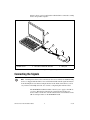
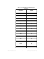
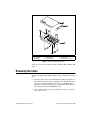
CB-27 CONNECTOR BLOCK INSTALLATION GUIDE
This installation guide describes how to connect the CB-27 connector
block. With the CB-27 connector block, you can easily connect analog and
digital signals to the following National Instruments (NI) 27-pin PCMCIA
data acquisition (DAQ) devices:
•
DAQCard-AO-2DC
•
DAQCard-500
•
DAQCard-516
•
NI PCMCIA-4350
Other NI PCMCIA DAQ devices may be compatible with the CB-27. Refer to the
device user manual for compatibility information.
Note
The CB-27 consists of a connector block with 28 screw terminals and a
30-position right angle connector with ejector ears. Each screw terminal
corresponds to a pin number on the 30-position connector. Refer to the
DAQ device user manual for connector pinout information.
Conventions
The following conventions are used in this guide:
»
The » symbol leads you through nested menu items and dialog box options
to a final action. The sequence File»Page Setup»Options directs you to
pull down the File menu, select the Page Setup item, and select Options
from the last dialog box.
This icon denotes a note, which alerts you to important information.
This icon denotes a caution, which advises you of precautions to take to
avoid injury, data loss, or a system crash. When this symbol is marked on
the product, refer to the Read Me First: Safety and Radio-Frequency
Interference document, shipped with the product, for precautions to take.
DAQCard™, National Instruments™, NI™, and ni.com™ are trademarks of National Instruments Corporation. Product and
company names mentioned herein are trademarks or trade names of their respective companies. For patents covering
National Instruments products, refer to the appropriate location: Help»Patents in your software, the patents.txt file
on your CD, or ni.com/patents.
ni.com
© 1995–2002 National Instruments Corp. All rights reserved.
October 2002
320933C-01
bold
Bold text denotes items that you must select or click in the software, such
as menu items and dialog box options. Bold text also denotes parameter
names.
italic
Italic text denotes variables, emphasis, a cross reference, or an introduction
to a key concept. This font also denotes text that is a placeholder for a word
or value that you must supply.
monospace
Text in this font denotes text or characters that you should enter from the
keyboard, sections of code, programming examples, and syntax examples.
This font is also used for the proper names of disk drives, paths, directories,
programs, subprograms, subroutines, device names, functions, operations,
variables, filenames and extensions, and code excerpts.
What You Need to Get Started
To set up and use the CB-27, you need the following components:
❑ A computer
❑ CB-27 connector block
❑ CB-27 Connector Block Installation Guide
❑ PR27-30F I/O cable or PSH 32-30F cable (for the NI PCMCIA-4350)
❑ CB-27 quick-reference label
❑ One of the following devices:
–
NI PCMCIA-4350
–
DAQCard-AO-2DC
–
DAQCard-500
–
DAQCard-516
–
Other PCMCIA DAQ device
❑ Read Me First: Safety and Radio-Frequency Interference
❑ Number 2 Phillips screwdriver
❑ 1/8 in. flathead screwdriver
❑ Tie wraps
CB-27 Connector Block Installation Guide
2
ni.com
Installing the CB-27
Refer to the Read Me First: Safety and Radio-Frequency Interference document
before removing equipment covers or connecting/disconnecting any signal wires.
Caution
To connect the CB-27 to the DAQ device, complete the following steps:
1.
Insert the DAQ device into the PCMCIA slot of the computer.
2.
Plug the PR27-30F into the 27-pin connector on the DAQ device or the
PSH32-30F cable into the 32-pin connector on the NI PCMCIA-4350.
The PR27-30F and PSH32-30F cables are keyed so that you can insert them only
one way. Do not put strain on the I/O cable when inserting it into and removing it from the
DAQCard and the CB-27 connector block.
Caution
3.
Connect the signals to the CB-27 connector block. Refer to the
Connecting the Signals section for instructions.
4.
Insert the other end of the PR27-30F or PSH32-30F cable into the
CB-27 connector. The cable connector is keyed with a centered tab that
you must align with the slot on the CB-27 mating header. Firmly push
in the cable connector until the ejector ears on the CB-27 connector
snap into position.
Make sure that the PR27-30F ribbon cable or the PSH32-30F cable is not twisted
between the DAQ device and the CB-27.
Note
© National Instruments Corporation
3
CB-27 Connector Block Installation Guide
Figure 1 shows a typical configuration with the CB-27 connected to a DAQ
device and portable computer.
1
2
3
4
5
7
-2
CB
6
1
2
Portable Computer
PCMCIA Socket
3
4
PCMCIA DAQ device
PR27-30F or PSH32-30F I/O Cable
5
6
CB-27
I/O Signals
Figure 1. A Typical Configuration
Connecting the Signals
A blank quick-reference label, which shows the screw terminals for PCMCIA DAQ
devices, is shipped with the CB-27. You can fill in the blanks with the signal information
from the DAQ device user manual and put the label on the inside of the CB-27 cover for
easy reference. The DAQ device kit also contains a completed quick-reference label.
Note
The NI PCMCIA-4350 kit includes a label for you to apply to the CB-27
accessory. This label provides the pin correlation between these two
devices. Table 1 shows the correlation between the screw terminals on the
CB-27 and signal names on the NI PCMCIA-4350.
CB-27 Connector Block Installation Guide
4
ni.com
Table 1. Using the PCMCIA DAQ or NI PCMCIA-4350 Device
with the CB-27
© National Instruments Corporation
PCMCIA DAQ Device
Signal Name
CB-27 Screw
Terminal
AGND
1
CH0+
2
CH0–
3
CH1+
4
CH1–
5
CH2+
6
CH2–
7
CH3+
8
CH3–
9
CH4+
10
CH4–
11
CH5+
12
CH5–
13
CH6+
14
CH6–
15
CH7+
16
CH7–
17
IEX+
18
IEX–
19
RSVD1
20
RSVD2
21
GND
22
5
CB-27 Connector Block Installation Guide
Table 1. Using the PCMCIA DAQ or NI PCMCIA-4350 Device
with the CB-27 (Continued)
PCMCIA DAQ Device
Signal Name
CB-27 Screw
Terminal
DIO0
23
DIO1
24
DIO2
25
DIO3
26
DGND
27
To connect the signals to the connector block, refer to Figure 2 as you
complete the following steps:
1.
Make sure that the PR27-30F or PSH32-30F cable is disconnected
from the CB-27. Refer to the Removing the Cable section for
instructions.
2.
Remove the screws from the bottom of the CB-27, as shown in
Figure 2, to remove the top cover and the front panel.
3.
Connect the wires to the screw terminals by stripping off 6 mm
(0.25 in.) of the wire insulation and inserting the wires (26–18 AWG)
into the screw terminals. Tighten the terminal screws.
4.
After you connect the wires to the screw terminals, attach the wires to
the CB-27. Bunch the wires from one side of the connector block and
tie them to a strain-relief tab using a tie wrap. Repeat for the other side
of the connector block.
5.
Replace the front panel and the top cover and reinsert the screws. Make
sure all the wires come out of the front panel openings.
CB-27 Connector Block Installation Guide
6
ni.com
1
2
9
8
7
4
5
6
3
6
1
2
3
Top Cover
Front Panel
Tie Wrap
4
5
6
Strain-Relief Tabs
Signal Wires
Cover Screws
7
8
9
Screw Terminals
Ejector Ears
30-Position Connector
Figure 2. Connecting Signals to the CB-27
You now can connect the connector block to the PR27-30F or PSH32-30F
cable.
Removing the Cable
To remove the PR27-30F or PSH32-30F I/O cable, complete the following
steps:
1.
Grasp the cable connector near the DAQ device and pull it straight out.
If you pull the cable out using a rocking motion or pull directly on the
cable, you can damage the pins on the cable or on the DAQ device.
Remember to push on the latching ears of the PSH32-30F cable before
disconnecting it from the NI PCMCIA-4350.
2.
Press outward on the ejector ears of the CB-27 connector to pop the
cable connector out.
© National Instruments Corporation
7
CB-27 Connector Block Installation Guide
Specifications
These ratings are typical at 25 °C unless otherwise stated.
Maximum Working Voltage
Maximum working voltage refers to the signal voltage plus the
common-mode voltage.
Each input must remain within ±20 V of ground.
Safety
The CB-27 meets the requirements of the following standards for safety
and electrical equipment for measurement, control, and laboratory use:
Note
•
EN 61010-1, IEC 61010-1
•
UL 3121-1
•
CAN/CSA C22.2 No. 1010.1
For UL and other safety certifications refer to the product label or to ni.com.
Electromagnetic Compatibility
CE, C-Tick, and FCC Part 15 (Class A) Compliant
Electromagnetic emissions .....................EN 55011, ISM Group I,
Class A at 10 m
FCC Part 15A above 1 GHz
Electromagnetic immunity .....................Evaluated to EN 61326-1;
A1:1998, Table 1
For full EMC compliance, you must operate this device with shielded cabling. In
addition, all covers and filler panels must be installed. Refer to the Read Me First: Safety
and Radio-Frequency Interference document for FCC Regulatory statements and related
information.
Note
CE Compliance
The CB-27 meets the following amended essential requirements of
applicable European Directives for CE marking:
•
Low-Voltage Directive (safety): 73/23/EEC
•
Electromagnetic Compatibility Directive (EMC): 89/336/EEC
CB-27 Connector Block Installation Guide
8
ni.com
Refer to the Declaration of Conformity (DoC) for this product for any additional
regulatory compliance information. To obtain the DoC for this product, click Declaration
of Conformity at ni.com/hardref.nsf/. This Web site lists the DoCs by product
family. Select the appropriate product family, followed by the product, and a link appears
to the DoC in Adobe Acrobat format. Click the Acrobat icon to download or read the DoC.
Note
Technical Support Resources
NI Web Support
NI Web support is your first stop for help in solving installation,
configuration, and application problems and questions. Online
problem-solving and diagnostic resources include frequently asked
questions, knowledge bases, product-specific troubleshooting wizards,
manuals, drivers, software updates, and more. Web support is available
through the Technical Support section of ni.com.
Worldwide Support
NI has offices located around the world to help address your support needs.
You can access our branch office Web sites from the Worldwide Offices
section of ni.com. Branch office Web sites provide up-to-date contact
information, support phone numbers, email addresses, and current events.
If you have searched the technical support resources on our Web site
and still cannot find the answers you need, contact your local office or NI
corporate. For telephone support in the United States, dial 512 795 8248.
For telephone support outside the United States, contact your local branch
office:
Australia 03 9879 5166, Austria 0662 45 79 90 0, Belgium 02 757 00 20,
Brazil 55 11 3262 3599, Canada (Calgary) 403 274 9391,
Canada (Montreal) 514 288 5722, Canada (Ottawa) 613 233 5949,
Canada (Québec) 514 694 8521, Canada (Toronto) 905 785 0085,
China 86 21 6555 7838, Czech Republic 02 2423 5774,
Denmark 45 76 26 00, Finland 09 725 725 11, France 01 48 14 24 24,
Germany 089 741 31 30, Greece 01 42 96 427, Hong Kong 2645 3186,
India 91 80 4190000, Israel 03 6393737, Italy 02 413091,
Japan 03 5472 2970, Korea 02 3451 3400, Malaysia 603 9596711,
Mexico 001 800 010 0793, Netherlands 0348 433466,
New Zealand 09 914 0488, Norway 32 27 73 00, Poland 22 3390 150,
Portugal 210 311 210, Russia 095 238 7139, Singapore 65 6 226 5886,
Slovenia 3 425 4200, South Africa 11 805 8197, Spain 91 640 0085,
Sweden 08 587 895 00, Switzerland 056 200 51 51,
Taiwan 02 2528 7227, United Kingdom 01635 523545
© National Instruments Corporation
9
CB-27 Connector Block Installation Guide