1
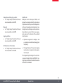
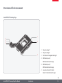
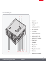
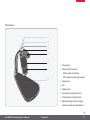
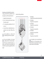
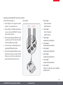
Leica LMT260 XY Scanning Stage User Manual Contents General Notes General Notes Important Safety Notes Symbols Used Safety Instructions 4 5 6 7 Introduction Congratulations!11 Standard Delivery and Optional Accessories 12 Overview of the Instrument 13 Assembly Leica LMT260 XY Scanning Stage with Leica TL5000 Ergo Glass Stage Plate and Adapters Leica LMT260 XY Scanning Stage Adjusting the Illumination of the Leica TL5000 Ergo Focal Plane Leica LMT260 XY Scanning Stage with Leica TL4000 Series (BFDF, RC, RCI) Glass Stage Plate and Adapters Leica LMT260 XY Scanning Stage Installation Cables and Terminals 17 17 18 19 Instrument Setup Leica LMT260 XY Scanning Stage Starting the Leica LMT260 XY Scanning Stage Operating the Leica LMT260 XY Scanning Stage 25 25 28 Service Care, Maintenance, Contact People Spare Parts 33 35 Specifications Technical Data Dimensional Drawings Leica LMT260 XY Scanning Stage HydraDT Control Unit CAN Handwheel 37 39 39 40 41 20 20 21 23 Leica LMT260 XY Scanning Stage User Manual General Notes Leica LMT260 XY Scanning Stage User Manual General Notes3 General Notes Safety concept Before using your Leica LMT260 XY scanning stage for the first time, please read the "Safety Concept" brochure, as well as the user manuals available on the DVD, both included with your instrument. They contain additional information on handling and care. Cleaning OO Do not use any unsuitable cleaning agents, chemicals or techniques for cleaning. OO OO Leica LMT260 XY Scanning Stage User Manual Never use chemicals to clean colored surfaces or accessories with rubberized parts. This could damage the surfaces, and products could be contaminated by abraded particles. In most cases, Leica Microsystems can provide special solutions on request. Some products can be modified, and we can offer special accessories for use in clean rooms. Servicing Repairs may only be carried out by Leica Microsystems trained service technicians. Only original Leica Microsystems spare parts may be used. OO Responsibilities of the person in charge of the instrument OO Please ensure that the Leica product is operated, maintained and repaired by authorized and trained personnel only. General Notes4 Important Safety Notes User manual The Leica LMT260 XY scanning stage can be set up in a variety of ways in the Leica product range. You can find information on individual system components on the DVD together with all relevant user manuals in additional languages. Please keep this DVD in a safe place, where it is available to all users. This user manual describes the special functions of the Leica LMT260 XY scanning stage and contains important instructions for its operational safety, maintenance, and accessories. The "Safety Concept" booklet and the user manuals available on the DVD contain additional safety information regarding the service work, requirements and the handling of the Leica LMT260 XY scanning stage, accessories and electrical accessories as well as general safety instructions. To maintain the unit in its original condition and to ensure safer operation, the user must follow the instructions and warnings contained in these user manuals. You can combine individual system articles with articles from external suppliers (e.g. cold light sources, etc.). Please consult the supplier's user manual and the safety instructions. Before installing, operating or using the instruments, read the user manuals listed above. In particular, please follow all safety instructions. Leica LMT260 XY Scanning Stage User Manual General Notes5 Symbols Used Warning! Safety hazard! This symbol indicates especially important information that is mandatory to read and observe. • Warning of hazardous electrical voltage This symbol indicates especially important information that is mandatory to read and observe. Danger due to hot surface This symbol warns against touching hot surfaces, e.g. those of light bulbs. Failure to comply can cause the following: Failure to comply can cause the following: Important information This symbol indicates additional information or explanations that are intended to provide clarity. OO OO Hazards to personnel Functional disturbances or damaged instruments Leica LMT260 XY Scanning Stage User Manual OO OO Hazards to personnel Functional disturbances or damaged instruments General Notes6 Safety Instructions Description OO The individual modules fulfill the highest requirements for observation and documentation with the Leica LMT260 XY scanning stage. Intended use OO See "Safety Concept" booklet and the user manuals available on the DVD. Non-intended use OO See "Safety Concept" booklet and the user manuals available on the DVD. The instruments and accessories described in this User Manual have been tested for safety and potential hazards. The responsible Leica affiliate must be consulted whenever the instrument is altered, modified or used in conjunction with non-Leica components that are outside of the scope of this manual. Unauthorized alterations to the instrument or noncompliant use shall void all rights to any warranty claims. Place of use OO See "Safety Concept" booklet and the user manuals available on the DVD. OO Electrical components must be placed at least 10 cm away from the wall and from flammable substances. OO Avoid large temperature fluctuations, direct sunlight and vibrations. These conditions can distort measurements and micrographic images. OO In warm and warm-damp climatic zones, the individual components require special care in order to prevent the growth of fungus. Neither the Leica LMT260 XY scanning stage nor its components may be used for surgical procedures, since they are not intended for that purpose. Leica LMT260 XY Scanning Stage User Manual General Notes7 Responsibilities of person in charge of instrument OO See "Safety Concept" booklet and the user manuals available on the DVD. Repairs, service work See "Safety Concept" booklet and the user manuals available on the DVD. OO OO Only original Leica Microsystems spare parts may be used. OO Avoid contact with powered electrical circuits, which can lead to injury. Ensure that: OO ...the Leica LMT260 XY scanning stage and accessories are operated, maintained and repaired by authorized and trained personnel only. OO ...all operators have read, understood and will observe this user manual, and particularly the safety regulations. Leica LMT260 XY Scanning Stage User Manual Transport Use the original packaging for shipping or transporting the individual modules of the Leica LMT260 XY scanning stage and the accessory components. OO OO In order to prevent damage from vibrations, pack all moving parts that (according to the user manual) can be assembled and disassembled by the customer in their original transport packaging and ship them appropriately. General Notes8 Integration in third-party products OO See "Safety Concept" booklet and the user manuals available on the DVD. Disposal OO See "Safety Concept" booklet and the user manuals available on the DVD. Legal regulations OO See "Safety Concept" booklet and the user manuals available on the DVD. EC Declaration of Conformity OO See "Safety Concept" booklet and the user manuals available on the DVD. Health risks Workplaces with microscopes facilitate and improve the viewing task, but they also impose high demands on the eyes and holding muscles of the user. Depending on the duration of uninterrupted work, asthenopia and musculoskeletal problems may occur. For this reason, appropriate measures for reduction of the workload must be taken: OO Optimal arrangement of workplace, work assignments and work flow (changing tasks frequently). OO Thorough training of the personnel, giving consideration to ergonomic and organizational aspects. The ergonomic optical design of Leica microscopes and design of the Leica LMT260 XY scanning stage are intended to reduce the exertion of the user to a minimum. Leica LMT260 XY Scanning Stage User Manual General Notes9 Introduction Leica LMT260 XY Scanning Stage User Manual Introduction10 Congratulations! Congratulations on purchasing the Leica LMT260 XY scanning stage by Leica Microsystems. The Leica LMT260 XY turns your Leica microscope into a universal, highly versatile tool for viewing and documenting microscopic objects or several objects simultaneously in a sample holder. Leica LMT260 XY Scanning Stage The Leica LMT260 XY scanning stage provides for direct positioning in two axes by means of linear motors. In addition, an absolute measurement of the stage position occurs, thereby eliminating the need for referencing after switching on. The flat assembly enables ideal accessibility to the object and the control elements of the microscope. A slide may be easily and precisely moved manually at any time by activating the Leica LMT260 XY scanning stage. In addition, the Leica LMT260 XY scanning stage features high-precision positionability, repeatability and minimal processing noise. External CAN Handwheel The ergonomically designed, dynamic CAN handwheel is equipped with precision roller bearings as well as a high-precision, magnetic measuring system, thereby offering high resolution to control the stage precisely. The CAN handwheel speed can be varied by means of two switches and is optimized for both left-hand and right-hand operation. External Control Unit HydraDT Using the external control unit HydraDT, five Leica LMT260 XY scanning stage positions can be stored and automatically recalled by pressing a button. The zero position (center position) of the Leica LMT260 XY scanning stage can also be automatically recalled by pressing a button. Leica LMT260 XY Scanning Stage User Manual Introduction11 Standard Delivery and Optional Accessories Standard delivery Optional accessories: Adapter plates 1 1 3 2 4 2 3 4 5 6 7 8 The Leica LMT260 XY scanning stage's standard delivery includes: 1 2 3 4 5 6 7 8 9 Leica LMT260 XY scanning stage External control unit HydraDT Power cable CAN cable External CAN handwheel USB cable HDMI cable (sensor X) (fixed onto the stage) HDMI cable (sensor Y) (fixed onto the stage) Motor X+Y-cable (fixed onto the stage) 1 Adapter plate for the Leica TL5000 Ergo transmitted light base 2 Adapter plate for the Leica TL4000 series (RCI, RC & BFDF) 3 Glass stage plate 4 Live on Stage sample holder 160 x 110 mm Additional sample holders are available in dimensions 160 x110 mm, information available upon request or in the Leica Live on Stage sample holder brochure. 9 Leica LMT260 XY Scanning Stage User Manual Introduction12 Overview of the Instrument Leica LMT260 XY Scanning Stage 4 5 6 1 2 1 Transport carriage Y 2 Transport carriage X 3 3 Push button with integrated status light 4 HDMI cable (sensor X) HDMI cable fixed onto the stage 5 HDMI cable (sensor Y) HDMI cable fixed onto the stage 6 Connection for motor X+Y-cable Motor X+Y-cable fixed onto the stage Leica LMT260 XY Scanning Stage User Manual Introduction13 External Control Unit HydraDT 1 2 1 Push buttons 1-6 2 LED status displays 1-8 3 On/off switch 4 Cover for power socket F3.15A 5 Power supply connection 6 Service connection 7 Network connection, no function 8 Connection for motor X+Y-cable 9 Connection for RS232-1, no function 10 HDMI port (sensor X) 11 CAN1 connection 12 HDMI port (sensor Y) 13 CAN2 connection 3 4 5 11 13 15 6 7 8 9 10 12 14 14 HDMI port (sensor Z), no function 16 15 USB connection 16 Connection for RS232-2, no function Leica LMT260 XY Scanning Stage User Manual Introduction14 CAN Handwheel 1 2 3 4 5 6 7 1 CAN connection 2 LED below the CAN connection LED illuminated red: initializing 8 LED no longer illuminated: ready to operate 3 Clamping screw 4Shim 5 Retaining stirrup 6 Setting wheel for controlling the Y-axis 7 Setting wheel for controlling the X-axis 8 Right and left toggle switch for setting the minimum or maximum speed for both axes Leica LMT260 XY Scanning Stage User Manual Introduction15 Assembly Leica LMT260 XY Scanning Stage User Manual Assembly16 Leica LMT260 XY Scanning Stage with Leica TL5000 Ergo Glass Stage Plate and Adapters General notes This chapter shows an example of assembly of the Leica LMT260 XY scanning stage on a transmitted light base. The Leica LMT260 XY scanning stage is a precision instrument. During installation, avoid subjecting the stage to impact or severe vibrations. Remove the glass stage plate 1 Fit the adapter SW 1.5 3 SW 2.5 3 3 2 3 1 2 3 1. Press the glass stage plate downward as shown. 2. Remove the glass stage plate. 3. Loosen and remove the three set screws with a 1.5 mm Allen key. 3 1. Mount the extension plate as shown. 2. Push the extension plate to the left using gentle pressure. Ensure that the extension plate holes are positioned over the threads of the base. 3. Fasten the extension plate with three M3x6 Allen screws using a 2.5 mm Allen key. Leica LMT260 XY Scanning Stage User Manual Assembly17 Leica LMT260 XY Scanning Stage Mount the Leica LMT260 XY scanning stage Remove the transport anchor 3 Mount the glass stage plate (optional) SW 3 1.6 Nm 2 1 3 1 1. Remove the transport anchor screws. Secure the axes with your fingers for the following steps, so as not to jam the axes by the movements of the Leica LMT260 XY scanning stage. Keep the safety screws; they are needed for retransporting the stage. Do not transport the stage without first installing the safety screws. Leica LMT260 XY Scanning Stage User Manual 2 1 1. Place the Leica LMT260 XY scanning stage to fit precisely on the adapter plate. 2. Gently tighten both front M4x12 Allen screws with a 3 mm Allen key. 1 1. Mount the glass stage plate (optional) or the Leica Live on Stage sample holder (optional) as shown. 3. Gently tighten both rear M4x12 Allen screws with a 3 mm Allen key. 4. To guarantee a high level of precision for the stage, tighten the four screws crosswise exactly 1.6 Nm using a torque wrench. Assembly18 Adjusting the Illumination of the Leica TL5000 Ergo Focal Plane Save settings Select RC mode Activate the menu selection 1 3 2 1 Follow these steps to adapt the illumination of the Leica TL5000 Ergo focal plane to the additional height of the Leica LMT260 XY scanning stage: 1. Press and hold the "DF" and "Light on/off" buttons for 10 seconds. The "BF", "RC" and "DF" LEDs flash three times synchronously, then just one LED flashes to display the selected mode. Leica LMT260 XY Scanning Stage User Manual 2. Press the "RC" button to adjust the Leica TL5000 Ergo for use with the Leica LMT260 XY scanning stage. The LED for the selected RC mode flashes continuously. 3. Press the "Light on/off" button to save the configured settings and exit the menu selection. The"BF" mode is designed for use with the motorized/manual Leica IsoProTM x/y-stage, "DF" for use with the transmitted light base Leica TL5000 Ergo in standalone operation (default setting). Assembly19 Leica LMT260 XY Scanning Stage with Leica TL4000 Series (BFDF, RC, RCI) Glass Stage Plate and Adapters Remove the glass stage plate Remove the standard stage Install the adapter SW 3 1 1 SW 3 2 1 1 2 1 2 2 1. Press the glass stage plate downward as shown. 1. Loosen and remove the four Allen screws with a 3 mm Allen key. 2. Remove the glass stage plate. 2. Remove the standard stage. 2 2 1 1. Position the adapter exactly. 2. Fasten the adapter with four M4x35 Allen screws using a 3 mm Allen key. This chapter shows an example of assembly of the Leica LMT260 XY scanning stage on a transmitted light base. Images and descriptions may vary when using another transmitted light base. The Leica LMT260 XY scanning stage is a precision instrument. During installation, avoid subjecting the stage to impact or severe vibrations. Leica LMT260 XY Scanning Stage User Manual Assembly20 Leica LMT260 XY Scanning Stage Remove the transport anchor Mount the Leica LMT260 XY scanning stage 3 Mount the glass stage plate (optional) SW 3 1.6 Nm 2 1 3 1 1. Remove the transport anchor screws. Secure the axes with your fingers for the following steps, so as not to jam the axes by the movements of the Leica LMT260 XY scanning stage. Keep the safety screws; they are needed for retransporting the stage. Do not transport the stage without first installing the safety screws. Leica LMT260 XY Scanning Stage User Manual 2 1 1 1. Place the Leica LMT260 XY scanning stage to fit precisely on the adapter. 2. Gently tighten both front M4x12 Allen screws with a 3 mm Allen key. 1. Mount the glass stage plate (optional) or the Leica Live on Stage sample holder (optional) as shown. 3. Gently tighten both rear M4x12 Allen screws with a 3 mm Allen key. 4. To guarantee a high level of precision for the stage, tighten the four screws crosswise exactly 1.6 Nm using a torque wrench. Assembly21 Installation Leica LMT260 XY Scanning Stage User Manual Installation22 Cables and Terminals Leica LMT260 XY scanning stage, HydraDT control unit and CAN handwheel 1. Connect the CAN handwheel via the CAN connection to the CAN1 port of the HydraDT control unit using a CAN cable. 1 1 2. Connect the Leica LMT260 XY scanning stage to the corresponding port of the HydraDT control unit using a Motor X+Y cable. 3. Connect the Leica LMT260 XY scanning stage to the corresponding HDMI ports of the HydraDT control unit using the HDMI cables (sensor X and sensor Y). 4 5 3 6 3 2 Leica LMT260 XY Scanning Stage User Manual 4. To control the Leica LMT260 XY scanning stage using software, connect the USB cable to the corresponding port of the HydraDT control unit and the computer. 5. Connect the power cord to the corresponding port of the HydraDT control unit. 6. Connect the power cable to a grounded socket. The Leica LMT260 XY scanning stage and the HydraDT control unit are matched to ensure the best possible performance. Using the serial number of the Leica LMT260 XY scanning stage and the adhesive label on the rear side of the HydraDT control unit you can check whether the two instruments are compatible. Installation23 Instrument Setup Leica LMT260 XY Scanning Stage User Manual Instrument Setup24 Leica LMT260 XY Scanning Stage Starting the Leica LMT260 XY Scanning Stage Switching on the HydraDT control unit Make sure that all required cables are properly connected and the computer is switched on. 1 1. Switch on the HydraDT control unit using the on/off switch. This will be confirmed by the LED of status display 8 lighting up (see page 31). 2. The Leica LMT260 XY scanning stage is initialized, which can take up to 30 seconds. 3. As soon as status displays 1 and 2 light up (see page 31), the Leica LMT260 XY scanning stage is ready to operate. 4. Follow the software's instructions for the configuration. Leica LMT260 XY Scanning Stage User Manual Instrument Setup25 Setting up Leica Application Suite (LAS) 1. Start the LAS hardware configuration. LAS supports the Leica LMT260 XY scanning stage Version 4.2 and newer. 2. Select "Options" >> "Hardware Setup". 3. At the "Stage" option select "ITK Hydra XY". Now the USB port of the Leica LMT260 XY scanning stage is displayed as COM port. In Windows Device Manager you can see which COM port the Leica LMT260 XY scanning stage is using. 4. Click "Test" to check the configured settings. 5. Confirm the settings with "Apply". Leica LMT260 XY Scanning Stage User Manual Instrument Setup26 Setting up Leica Application Suite Advanced Fluorescence (LAS AF) 1. Start the LAS AF hardware configuration. LAS AF supports the Leica LMT260 XY scanning stage Version 3.2 and newer. 2. Select "Hardware Setup". 3. At the "External stage" option select "ITK Hydra XY". Now the USB port of the Leica LMT260 XY scanning stage is displayed as COM port. In Windows Device Manager you can see which COM port the Leica LMT260 XY scanning stage is using. 4. Click "Test" to check the configured settings. Leica LMT260 XY Scanning Stage User Manual 5. Confirm the settings with "Apply". Instrument Setup27 Operating the Leica LMT260 XY Scanning Stage General notes The Leica LMT260 XY scanning stage can be operated: OO Using the software (Leica Application Suite or Leica Application Suite Advanced Fluorescence). For additional information, please refer to the corresponding online help. OO With the external CAN handwheel. For additional information, please refer to page 29. OO Directly on the Leica LMT260 XY scanning stage. For additional information, please refer to page 29. OO With the HydraDT control unit. For additional information, please refer to page 30. Leica LMT260 XY Scanning Stage User Manual Information about the speed Speed of the Leica LMT260 XY scanning stage when controlling by means of software: maximum speed = 200 mm/s, maximum acceleration = 100 mm/s² Adjust the external CAN handwheel 2 1 Selection of the minimum or maximum speed on the CAN handwheel (see page 29) has no effect on the speed of the Leica LMT260 XY scanning stage when controlling by means of software. 1. Loosen the locking screw. 2. Position the CAN handwheel to match your operating preference and retighten the locking screw. Make sure that all required cables are properly connected. Instrument Setup28 Operating using the CAN handwheel Moving the Leica LMT260 XY scanning stage by hand The green LED of the push button indicates: OO LED off: No power supply or stage is initializing (approx. 30 seconds). OO LED flashes continuously: One or both axes can be moved freely. OO LED is lit continuously: Leica LMT260 XY scanning stage is ready to operate for monitoring by means of software, CAN handwheel or HydraDT control unit. 2 3 2 1 1 1 1. Press the toggle switch forward or backward for more than 0.25 seconds to switch between the minimum and maximum speeds of the Leica LMT260 XY scanning stage. 1. If the LED is lit: Press the push button; the Leica LMT260 XY scanning stage can be moved freely; the CAN handwheel, HydraDT control unit and software will not function, and the LED flashes. 2. Move the Leica LMT260 XY scanning stage in the X direction. 2. Now the Leica LMT260 XY scanning stage can be carefully moved by hand. 3. Move the Leica LMT260 XY scanning stage in the Y direction. 3. Press the button again to refasten the Leica LMT260 XY scanning stage and to control using the CAN handwheel, HydraDT or software again; the LED lights up and stays green. For additional information about the minimum or maximum speeds, please refer to page 38. Leica LMT260 XY Scanning Stage User Manual Instrument Setup29 Operating using the HydraDT control unit Saving a position of the Leica LMT260 XY scanning stage on one of the push buttons 2-6. 1. Approach the desired position. 2. Press the desired push button for more than three seconds: OO The corresponding coordinates (X and Y) are saved. OO A successful save is indicated by the corresponding status display flashing three times. Saved coordinates are retained until overwritten by another save operation. The saved coordinates are the target coordinates of the last motorized movement. If the stage is unlocked during the save, what is saved is not the current position, but instead the last position approached with the motor! Leica LMT260 XY Scanning Stage User Manual Functions of the push buttons 1 2 3 4 5 6 1 Push button 1 To approach the zero position (center position) 2 Push button 3 To approach or save position 1 3 Push button 4 To approach or save position 2 4 Push button 5 To approach or save position 3 5 Push button 6 To approach or save position 4 6 Push button 2 To approach or save position 5 Five positions can be saved with push buttons 2 to 6. These positions are not identical with the saved positions that can be saved via the LAS or LAS AF software. Instrument Setup30 Operating using the HydraDT control unit, continued Function of status displays 1-8: Status displays OO Status displays 3-7 are assigned to savable positions 1-5 or push buttons 2-6. 1 Status display 1 LED on: X-axis fixed 1 234 LED off: X-axis free 5678 Status displays 1-8 illuminate continuously as soon as the Leica LMT260 XY scanning stage is ready to operate. 2 Status display 2 OO If the corresponding push button for saving a position is pressed for more than three seconds, the LED goes out briefly. 3 Status display 3 saved position 1/push button 3 OO A successful save is indicated by the corresponding LED flashing three times. OO OO If the corresponding push button is pressed briefly (less than three seconds), the LED flashes once and the last-saved position is approached. No new position is saved. LED on: Y-axis fixed LED off: Y-axis free 4 Status display 4 saved position 2/push button 4 5 Status display 5 saved position 3/push button 5 6 Status display 6 saved position 4/push button 6 7 Status display 7 saved position 5/push button 2 8 Status display 8 LED lights up and stays green: Operating voltage is present Leica LMT260 XY Scanning Stage User Manual Instrument Setup31 Service Leica LMT260 XY Scanning Stage User Manual Service32 Care, Maintenance, Contact People General We hope you enjoy using your scanning stage. Leica products are renowned for being robust and for their long service life. Observing the following care and cleaning tips will ensure that even after decades your Leica scanning stage will continue to work as well as it did on the very first day. Warranty benefits The guarantee covers all faults in materials and manufacture. It does not, however, cover damage resulting from careless or improper handling. Contact address If your instrument no longer works perfectly, please contact your Leica Microsystems representative. You can find information on worldwide representatives on the Leica Microsystems website: Care OO For good optical results it is important to keep all optical components clean. OO If any optical surface becomes badly coated with dust or dirt, flush the surface using a syringe or by brushing it off with a camel hair brush before attempting to wipe it clean. Plugs, optical systems and mechanical parts must not be disassembled or replaced, unless doing so is specifically permitted and described in this manual. OO Protect your microscope from oil and grease. OO Do not grease guide surfaces or mechanical parts. OO OO Optical surfaces should be cleaned using a lint-free cloth, lens cloth or cotton swab soaked in pure ethanol or a commercially available glass cleaner. OO Avoid excessive use of solvents. The lintfree cloth, lens cloth or cotton swab should be soaked with solvent, but not so wet that solvent runs over the lens. OO Protect your microscope from moisture, fumes and acids and from alkaline, caustic and corrosive materials, and keep chemicals away from the instruments. www.leica-microsystems.com Leica LMT260 XY Scanning Stage User Manual Service33 Care, Maintenance, Contact People (continued) Protection from dirt Dust and dirt will affect the quality of your results. OO OO Put an optionally available dust cover over the microscope when it will not be used for a long time. Keep accessories in a dust-free place when not in use. Cleaning polymer components Some components are made of polymer or are polymer-coated. They are, therefore, pleasant and convenient to handle. The use of unsuitable cleaning agents and techniques can damage polymers. Leica LMT260 XY Scanning Stage User Manual Permitted measures OO Clean the microscope (or parts of it) using warm soapy water, then wipe using distilled water. OO OO OO For stubborn dirt, you can also use pure ethanol. When doing so, follow the corresponding safety instructions. Remove dust with a pneumatic rubber bulb and a soft brush. Clean the objectives with special optics cleaning cloths and pure ethanol. Servicing Repairs may only be carried out by Leica Microsystems-trained service technicians. Only original Leica Microsystems spare parts may be used. OO Danger of electric shock Risk of electric shock. Removing the cover of the Leica LMT260 XY scanning stage and the HydraDT control unit exposes electrically live parts, which, if touched, can cause potentially fatal injuries. Have technical service carried out by a Leica Microsystems authorized dealer. Service34 Spare Parts 1 2 2a 2b 3 4 5 Leica LMT260 XY Scanning Stage User Manual Item Leica article number Designation 1 10727010 CAN cable 2 10727011SP External handwheel 2a 10727012SP Handwheel 2b 10727013SP Handwheel stand 3 10727014 CAN terminator 4 10727015 USB cable 5 10727016 Transport anchor screws Service35 Specifications Leica LMT260 XY Scanning Stage User Manual Specifications36 Technical Data Leica LMT260 XY scanning stage Parameter Item Notes Max. loading weight < 0.5 kg 1.0 kg 1.5 kg (max.) Max. acceleration (X/Y) 1.0/2.0 m/s2 1.0/2.0 m/s2 0.1/0.1 m/s2 Min. acceleration (X/Y) Max. travel speed 1 µm/s 500 mm/s 2 500 mm/s Min. travel speed 100 mm/s Travel range (X-axis x Y-axis) 120 x 80 mm Positioning resolution 200 mm/s 5 nm Limited by the possible acceleration and the positioning range At 20 °C Positioning accuracy < ± 1.0 µm < ± 2.0 µm < ± 4.0 µm At 20 °C Position repeatability £ ± 0.25 µm < ± 0.5 µm < ± 1.0 µm At 20 °C Peak force 10 N Nominal force 8 N Dimensions 374 x 247 x 31.1 mm Without connections 438 x 367 x 31.1 mm With connections Operating voltage 100 to 240 V AC, 50/60 Hz Internal power supply 24 V DC Weight approx. 4.8 kg Operating temperature +10 to +40 °C Leica LMT260 XY Scanning Stage User Manual Power supply voltage Specifications37 HydraDT control unit CAN handwheel Parameter Item Parameter Item Operating temperature +10 to +40 °C Operating temperature 0 to +40 °C Storage temperature -20 to +70 °C Storage temperature -20 to +50 °C Power supply (max.) 100 to 240 V AC, 50/60 Hz Power supply (max.) 0 to 36 V Power output 1.1 W Max. power consumption P max = 160 W Weight 1.6 g Weight approx. 1.1 kg Maximum speed Setting wheel (gear) 5 mm/turn Max. speed (Leica LMT260 XY scanning stage) 50 mm/s Max. acceleration (Leica LMT260 XY scanning stage) 200 mm/s2 Minimum speed Leica LMT260 XY Scanning Stage User Manual Setting wheel (gear) 0.5 mm/turn Max. speed (Leica LMT260 XY scanning stage) 2.5 mm/s Max. acceleration (Leica LMT260 XY scanning stage) 10 mm/s2 Specifications38 Dimensional Drawings Leica LMT260 XY Scanning Stage 31.1 438 165 68.15 367 247 164 45 45 51.85 374 Dimensions in mm Leica LMT260 XY Scanning Stage User Manual Specifications39 HydraDT Control Unit 160 72 182 185 72 185 168 148 148 165 Dimensions in mm Leica LMT260 XY Scanning Stage User Manual Specifications40 CAN Handwheel 47 140 168 179 145 210 210 140 Dimensions in mm Leica LMT260 XY Scanning Stage User Manual Specifications41 The productive cooperative effort "with the user, for the user" has always been the basis for the innovative strength of Leica Microsystems. On this, we have developed our five corporate values: pioneering, high-end quality, team spirit, dedication to science, and continuous improvement. We call making these values reality: Living up to Life. INDUSTRY DIVISION The Leica Microsystems Industry Division's focus is to support customers' pursuit of the highest quality end result by providing the best and most innovative imaging systems for their needs to see, measure, and analyze microstructures. Its solutions are used in routine and research industrial applications, in materials science and quality control, in forensic science investigations, and educational applications. Leica Microsystems – an international company with an experienced worldwide customer service network. Internationally active Phone Fax Australia ∙ North Ryde +61 2 8870 3500 2 9878 1055 Belgium ∙ Diegem +32 2 790 98 50 2 790 98 68 Denmark ∙ Ballerup +45 4454 0101 4454 0111 Germany ∙ Wetzlar +49 64 41 29 40 00 64 41 29 41 55 England ∙ Milton Keynes +44 800 298 2344 1908 246312 France ∙ Nanterre Cedex +33 811 000 664 1 56 05 23 23 Italy ∙ Milan +39 02 574 861 02 574 03392 Japan ∙ Tokyo +81 3 5421 2800 3 5421 2896 Canada ∙ Concord/Ontario +1 800 248 0123 847 405 0164 Korea ∙ Seoul +82 2 514 65 43 2 514 65 48 The Netherlands ∙ Rijswijk +31 70 4132 100 70 4132 109 Austria ∙ Vienna +43 1 486 80 50 0 1 486 80 50 30 Portugal ∙ Lisbon +351 21 388 9112 21 385 4668 Sweden ∙ Kista +46 8 625 45 45 8 625 45 10 Switzerland ∙ Heerbrugg +41 71 726 34 34 71 726 34 44 Singapore +65 6779 7823 6773 0628 Spain ∙ Barcelona +34 93 494 95 30 93 494 95 32 USA ∙ Buffalo Grove/Illinois +1 800 248 0123 847 405 0164 2564 6699 2564 4163 21 6387 6606 21 6387 6698 People's Republic of China ∙ Hong Kong ∙ Shanghai +852 +86 Order No.: 10IDD12060EN_2 /23/05/2013 ∙ Copyright © 2013 Leica Microsystems (Schweiz) AG, Max Schmidheiny Strasse 201, Heerbrugg, CH-9435 Switzerland. Subject to change. LEICA and the Leica Logo are registered trademarks of Leica Microsystems IR GmbH. www.leica-microsystems.com