1
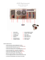
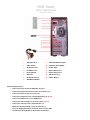
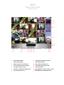
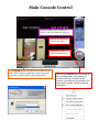
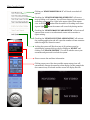
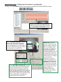
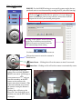
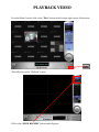
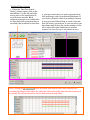
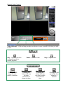
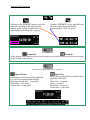
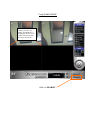
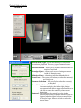
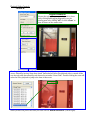
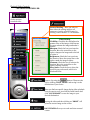
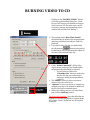
HYBRID VIDEO RECORDER
USER TRAINING GUIDE
(HVR)
Version 2.6.5
Includes…
HVR QUICK START GUIDES
HVR USER TRAINING GUIDE
WARRANTY INFORMATION
SOFTWARE CD
Vision Controls Corporation
455 E. Industrial Drive
P.O. Box 94
Hartland, WI 53029
Technical Support: 262.369.8798
Sales & Service: 262.369.8797
eFAX: 312.602.1356
www.visioncontrols.net
Software CD Enclosed:
1. QUICK START GUIDE
2. USER TRAINING GUIDE
3. REMOTE USER TRAINING GUIDE
4. COMPLETE USER MANUAL
5. 2007 WARRANTY INFORMATION
HVR Rackmount
Quick Start Guide
Hardware Setup
1
Power Switch
8
Analog DVI Monitor Output
2
AC Power Socket
9
Composite Video Output
3
PS/2 Mouse Port
10
Remote Input
4
PS/2 Keyboard
11
Camera Connector 1
5
USB Port
12
Camera Connector 2
6
RJ-45 Ethernet Port
13
USB License Key
7
VGA Monitor Output
14
Camera Dongle
Quick Setup Instructions:
•
Connect the power cord to the AC power socket (2)
•
Connect the keyboard and mouse to the correct ports (4) (3)
•
Connect the ethernet cable if necessary (6)
•
Connect the monitor(s) to the corresponding port(s) (7) (8) (9)
•
Connect the USB license (13) dongle to a USB port (5)
•
Connect the camera dongles to the correct ports (11) (12)
•
Connect the camera(s) to the camera dongles (14)
•
Make sure the power switch is in the on position I (1)
•
Press the toggle power button located on the front of the DVR
•
All camera(s) should display on the monitor after booting
HVR Tower
Quick Start Guide
Hardware Setup
1
Side Door Latch
9
Analog DVI Monitor Output
2
Power Switch
10
Composite Video Output
3
AC Power Socket
11
Remote Input
4
PS/2 Mouse Port
12
Camera Connector 1
5
PS/2 Keyboard
13
Camera Connector 2
6
USB Port
14
USB License Key
7
RJ-45 Ethernet Port
15
Camera Dongle
8
VGA Monitor Output
Quick Setup Instructions:
•
Connect the power cord to the AC power socket (3)
•
Connect the keyboard and mouse to the correct ports (4) (5)
•
Connect the ethernet cable if necessary (6)
•
Connect the monitor(s) to the corresponding port(s) (8) (9) (10)
•
Connect the USB license (14) to a USB port (6)
•
Connect the camera dongles to the correct ports (12) (13)
•
Connect the camera(s) to the camera dongles (15)
•
Make sure the power switch is in the on position I (2)
•
Press the toggle power button located on the front of the DVR
•
All camera(s) should display on the monitor after booting
HVR
Quick Start Guide
Software Setup
1
Exit the HVR Software
8
Play: Brings up playback interface
2
Camera (live display)
9
Time: Date and Time
3
Guard: Setup for event detection
10
Disk: Shows available space
4
Scan: Turn on/off auto scan option
11
Views: Change the layout views
5
Set: General system setup
12
PTZ: PTZ controls
6
Schedule: Scheduled recording setup
13
Max: Maximizes cameras / hides controls
7
Start: Start/Stop services
14
Min: Minimizes the HVR application
Main Console Control
Minimizes HVR software / Makes the
camera(s) full screen without logging out.
Red light present means
camera is recording.
“In:0, Out:0” shows
counting application is on.
The POWER button will allow you to either log out
of the HVR software completely or just logout your
username to default back to the bootup screen.
Click on the START button to bring up
the recording menu. From here you
can start and stop: monitoring the
cameras, recording on the cameras, the
smart guard system, and the counting
application.
Main Console Control
Clicking on “START MONITOR ALL” will check or uncheck all
options.
Checking the “START RECORDING SCHEDULE” will start or
stop recording on all cameras. You will know that any given camera is
recording, represented by a light in the upper right of that camera
view. A red light
A green light
means that the camera is recording at all times.
means the camera will record only during motion.
Checking the “START SMART GUARD SYSTEM” will activate all
cameras that are set to record unusual events such as motion or
object missing.
Checking the “START COUNTING APPLICATION” will activate
the counting application and will count the number of times someone
walks through the “detection zones”.
Locking the system will block out use of all options except for
unlocking the system which you do by clicking on “START” and
clicking on “UNLOCK SYSTEM”. You will be asked to enter your
username and password to unlock the system.
Shows current date and time information.
Clicking on any one of the nine possible camera setup views will
automatically change the cameras to that display. In this example the
four camera array is selected and the screen will display like this.
Main Console Control - Setting up each camera’s recording info
Clicking on the “SCHEDULE” button will bring up the SCHEDULE CONFIGURATION window.
Double-click on the recording line of the
camera you wish to setup. This will bring
up the ENCODING OPTIONS window.
Have “ALWAYS RECORD” selected
and use the “Start Time” and “End
Time” to dictate when recording will
start and stop each day. A Start Time of
00:00 and End Time of 23:59 will have
the camera set to record all day.
Select “RECORD ON MOTION” to have
the camera only record during movement
through the Detection Zone. Create the
Detection Zone by holding down the left
button and dragging the box to the desired
size and location. “Pre-record” and “Postrecord” is the number of seconds the HVR
will record for prior to and after the
motion inside of the motion box.
Sensitivity: Click and
move the control bar to the
right to increase sensitivity,
that is, a relatively small
movement will trigger the
alarm. Move to the left to
reduce the sensitivity of
movement detection. Set up
an appropriate Sensitivity
value will reduce the chance
of false alarm. For example,
you can lower the
Sensitivity to avoid the
alarm being triggered by a
swinging tree in the breeze.
Interval: Click and move
the control bar to the right
to increase interval time, so
that the alarm will only be
triggered when the
movement lasts longer.
Move to the left to reduce
the interval time.
Main Console Control
- PTZ
PRESET: Use the PRESET settings to save specific camera angles that are
quick and easier to use than manually rotating the PTZ (also called touring).
To save a specific setting, rotate the camera to the desired position.
Click on the button and click on “preset01”. You can change the
name of that preset point for easy reference. When done click OK.
Repeat this for all of your desired preset points.
Clicking on the PRESET arrow will bring
up the list of available preset positions.
Click on the preset you want to have the
PTZ camera jump to that setting.
Use these arrows to zoom in and zoom out.
Click on the arrows to move the camera in
that direction.
Auto Focus – Clicking this will set the camera to Auto Focus mode.
Auto Pan – Clicking on this will set the camera to automatically rotate.
If you right-click on the PTZ
camera view and click ENABLE
MOVE, your curser will change to
a movement curser
and you
can click anywhere on the PTZ
camera screen and have the
camera move there instantly. (This
is the most efficient way to move
the camera if using the buttons is
too slow.)
Clicking here will bring up the
Preset list. Just click on the preset
position you want the PTZ camera
to jump to.
PLAYBACK VIDEO
From the Main Console, click on the “Play” button in the bottom-right corner of the screen.
This will bring up the “Playback” screen.
Click on the “OPEN RECORD” button under Options.
Playback Video Controls
1. When the “DateTime Search
Dialog” window opens, click on the
desired date. Use the left and right
arrows next to the month name to
scroll between months. Black
numbers represent no recorded video
for that date while red means there is
recorded video available for that date.
2. Find the camera that you want to playback and
click and drag to select your desired timeframe. If
you want to playback video from multiple cameras
at once you can click and drag to create a box and
that will select your cameras, or you can select your
time frame and click on the camera number on the
left to select that same timeframe for another
camera. You can view up to 16 cameras at once.
Note: Clicking the
button will show what specific times have actually been
recording. Red lines or dots above the video line will represent the time that that camera was
recording. This will mostly just be used to find motion recorded files.
Playback Video Controls
Video Slide bar – Click and drag anywhere on the bar to move yourself to the time you wish
to view.
Play – Anytime the video
is stopped, use this to
resume playback.
Previous
Clicking this will
jump the video
back by 5 minutes.
Pause – Pause all video.
Step Backward
Clicking this
button will step
the video
backward one
frame at a time.
Stop – Stop all video.
Step Forward
Clicking this
button will step
the video forward
one frame at a
time.
Next
Clicking this will
push video time
ahead by 3
minutes.
Playback Video Controls
Clicking on the “CUE IN” button on the left
will start recording a new clip from that
starting point. In this case this will be
represented by showing “IN :12:55:23”.
Clicking “CUE OUT” on the right will stop
the new temporary recording clip.
Represented by “OUT :12:57:32”.
Zoom Out
Zoom In
(When playing back multiple cameras at once, make sure to select the camera that you want to zoom
by left-clicking on the camera.)
Normal video playback speed is 1x (real time).
Speed Down
Clicking once will slow down the playback
to 1/2x of its normal playback speed.
Clicking a second time – 1/4x speed
Third time – 1/8x speed
Fourth time – 1/16x speed
Speed Up
Every time you click this the speed of video
playback will double.
Click once – 2x speed
Twice – 4x speed
Third time – 8x speed
Fourth time – 16x speed
Using SEARCH MODE
(Make sure to select which
camera you want to use
during “Search Mode” by
clicking the camera. A red
outline will represent that
the camera is selected.)
Click on “SEARCH”
Playback Video Controls
-SEARCH
Alarm Event Type - Search automatically for an unusual
event during playback. There are 5 types of unusual events:
General Motion – Allows you to scan the Detection Zone for
motion of any kind.
Foreign Object – Allows you to scan for lasting movement
inside the Detection Zone.
Missing Object – Alarm is set off when defined object is
removed from the Detection Zone.
Lose Focus – The system will inform you when the camera(s)
are losing focus.
Camera Occlusion – Will set off alarm when the camera(s)
are blocked.
Sensitivity - Click and move the control bar to the right to
increase sensitivity; the farther right, the less
movement it will take to trigger an alarm. Move to
the left to reduce the sensitivity of movement
detection.
Interval - Click and move the control bar to the right to
increase interval time so that the alarm will only be
triggered when the object has been removed from
the area for longer. Move to the left to reduce the
interval time.
Playback Video Controls
-SEARCH
Region Definition
Choose the region that you want the search to focus
on by clicking and dragging diagonally over the
viewing area or by clicking “All”. Or click “Clear” to
clear all boxes on the camera view.
Checking “Stop when found” will cause the playback video to stop every time an alarmed event
occurs. Otherwise leaving “Stop when found” unchecked will allow the playback video to search all the
way through while documenting each alarmed event under “Event Time”. Double-clicking the event will
cause the video playback to jump to the time of that event.
When you have the part of the video you want click on “BROWSE MODE” (bottom right).
Playback Video Controls
- OPTIONS CONTROLLER
This is the button you
click to retrieve
recorded video.
General Setting – Here you select to
have either the settings apply to all
cameras or just the selected camera by
clicking “active channel” or “all channels”.
Filter Setting
Visibility: Check the box and adjust the
gamma value of the image, which means
you may enhance the image and make it
cleaner.
Sharpen: Check the box to activate the
function. Move the control bar to the
right to sharpen the image and to the left
to soften it.
Brightness: Check the box to activate
the function. Move the control bar to the
right to make the image brighter.
Contrast: Check the box to activate the
function. Move the control bar to the
right to increase contrast.
Grey Scale: Check the box to show the
record in grey scale mode, which is in
black and white.
Create a clip using the
buttons. Than save the
clip by clicking “SAVE VIDEO” and saving it to the
destination of your choice.
When you find one specific image during video playback
that you want to save, just click the Pause button and
click “SAVE IMAGE” to save the image to your
desired destination.
Pausing the video and then clicking on “PRINT” will
print the current image on the screen.
LOG VIEWER allows you to track and view unusual
events.
BURNING VIDEO TO CD
Clicking on the “BACKUP VIDEO” button
will bring up the Backup Dialog box. From
here you will choose your desired settings for
what to burn to CD. (In most cases you will
not need to change any information in this
window and can just click “Backup”)
The settings under “Date Time Period”
should already be adjusted for the proper date
and time period that you had just viewed in
playback.
If you had a video clip that you made using
the clip buttons
, then the time period
for burning to CD will automatically adjust for
the time of the selected video clip.
Under “Select Camera(s)”, all the video
clips from any camera(s) you already had in
the playback should already be selected.
o You will want to click on the
“Calculate Size” button to make sure
that the file that you are burning or
saving are within the size parameters
of the CD.
The “Media” section is where you choose
where to save the video file to.
“Options” is where you check or uncheck any
unusual event logs to be burned in addition to
the file (the logs use minimal space).
When your settings are how you want them,
just click the “Backup” button.
For Your Information: Any video files that are
burned to CD cannot be played on a typical home
DVD player. These CD files can only be watched
from a PC.
Vision Controls Hardware Warranty
General Information
Vision Controls provides buyers of our products with a manufacturers’ standard 3 year limited warranty as
described within this document. The customer also has the option of purchasing an extended warranty.
During its duration this warranty covers parts and service related labor (freight is not included). After this
duration, the buyer assumes all part, labor and shipment costs. (Vision Controls offers service contracts for
additional technical support and support services. Contact your Vision Controls Media Specialist for
service contract information and terms.)
Limited Warranty Terms
Vision Controls manufactures its products from new hardware components in accordance with industry standard
practices. Vision Controls warrants its manufactured products against hardware defects and
workmanship. Vision Controls warrants its products for a limited, 3 year term beginning on the date of
invoice. This warranty covers against damage due to shipping the products to the customer. However, this
warranty does not cover damage due to external causes, including accident, abuse, misuse, variations or
problems with electrical power, natural disasters, servicing not authorized by Vision Controls Corporation,
usage not in accordance with product literature, failure to perform required preventative maintenance,
problems caused by third-party software, or problems resulting from hardware parts or components not
supplied by Vision Controls.
Warranty Coverage
As stated previously, warranty coverage becomes effective on the invoice date. Vision Controls will repair
or
replace products returned to our facility covered under this limited warranty. To request warranty service,
customers must call Vision Controls’ technical support within the warranty period to determine the
appropriate action. In the event that service is required, our technical support will require the buyer to
complete a Return Material
Authorization (RMA) Form. You can download this form from our website (www.visioncontrols.net).
Customers must ship the products to Vision Controls in the original packaging. If the original packaging is
unavailable, Vision Controls will supply the partner with the appropriate shipping container and inserts
upon request for a nominal fee. Any damage caused by failure to ship the product in an authorized shipping
container will not be covered under this product warranty.
The customer assumes responsibility for cost of shipping to Vision Controls. Only authorized shipment
methods will be acceptable. Vision Controls is not liable for any loss of product during shipment. If
authorized shipping methods are not used Vision Controls will not be held responsible for any damage
caused during shipping.
The customer should note that Vision Controls uses new and reconditioned parts made by various
manufacturers when performing warranty repairs and when building replacement products. In addition, the
customer should also note that Vision Controls owns all parts removed from replacement or repaired
products.
Extended Warranty
A one year extended warranty may purchased for select products for up to two additional years beyond the
standard one year warranty. The extended warranty option covers: software maintenance, software
upgrades, hardware
failure, remote pc and phone support.
The extended warranty costs $195 per system per year.
Main: (262) 369-8797…………………… www.visioncontrols.net
Support: (262) 369-8798………………… [email protected]
Fax: (312) 602-1356…………………….. [email protected]
Vision Controls Corporation
P.O. Box 94, 455 E. Industrial Dr. Bldg. 2, Hartland, WI 53029
Ph: 262-369-8797 Fax: 312-602-1356 www.visioncontrols.net