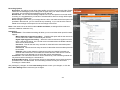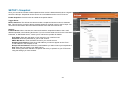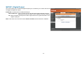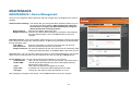
1
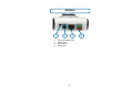
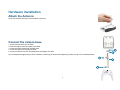
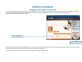
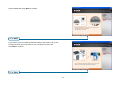
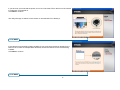
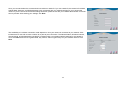
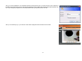
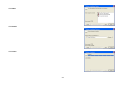
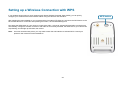
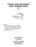
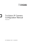
Table of Contents Package Contents .......................................................................................................................................................................................................................................1 Minimum System Requirements..................................................................................................................................................................................................................2 Introduction ..................................................................................................................................................................................................................................................3 Features and Benefits..................................................................................................................................................................................................................................4 Hardware Overview .....................................................................................................................................................................................................................................5 Hardware Installation ...................................................................................................................................................................................................................................7 Attach the Antenna ...............................................................................................................................................................................................................................7 Connect the camera base ....................................................................................................................................................................................................................7 Connect the Ethernet Cable .................................................................................................................................................................................................................8 Connect the Power Adapter .................................................................................................................................................................................................................8 Software Installation ....................................................................................................................................................................................................................................9 Install Setup Wizard Software....................................................................................................................................................................................................................14 Using the Setup Wizard .............................................................................................................................................................................................................................18 Using the ffdshow ......................................................................................................................................................................................................................................22 Adjusting the Camera Focus .....................................................................................................................................................................................................................25 Setting up a Wireless Connection with WPS.............................................................................................................................................................................................26 Using the Configuration Menu ...................................................................................................................................................................................................................27 LIVE VIDEO........................................................................................................................................................................................................................................28 LIVE VIDEO > Camera ...............................................................................................................................................................................................................28 SETUP................................................................................................................................................................................................................................................29 SETUP > Wizard .........................................................................................................................................................................................................................29 SETUP > Network Setup.............................................................................................................................................................................................................30 SETUP > Wireless ......................................................................................................................................................................................................................31 SETUP > Dynamic DNS..............................................................................................................................................................................................................32 SETUP > Image Setup................................................................................................................................................................................................................33 SETUP > Audio and Video ..........................................................................................................................................................................................................34 SETUP > Motion Detection .........................................................................................................................................................................................................36 SETUP > Time and Date.............................................................................................................................................................................................................37 SETUP > Recording....................................................................................................................................................................................................................38 SETUP > Snapshot .....................................................................................................................................................................................................................40 SETUP > Digital Output ..............................................................................................................................................................................................................42 MAINTENANCE .................................................................................................................................................................................................................................43 MAINTENANCE > Device Management.....................................................................................................................................................................................43 MAINTENANCE > Backup and Restore .....................................................................................................................................................................................44 MAINTENANCE > Firmware Upgrade ........................................................................................................................................................................................45 STATUS ..............................................................................................................................................................................................................................................46 STATUS> Device Info..................................................................................................................................................................................................................46 STATUS> Log..............................................................................................................................................................................................................................47 i HELP ..................................................................................................................................................................................................................................................48 Installing the DCS-2121 Behind a Router..................................................................................................................................................................................................49 1) Identify Your Camera on the Network .....................................................................................................................................................................................49 2) Assign a Local IP Address and Port for Your Camera ............................................................................................................................................................50 3) Open the HTTP Port ...............................................................................................................................................................................................................51 4) Open Virtual Server Ports to Enable Remote Image Viewing ................................................................................................................................................53 Viewing Your Camera Over the Internet ....................................................................................................................................................................................................54 Viewing Your Camera Over the Internet Behind a Router..................................................................................................................................................................54 Frequently Asked Questions......................................................................................................................................................................................................................55 Internet Camera Features ..................................................................................................................................................................................................................55 Internet Camera Installation ...............................................................................................................................................................................................................56 How to Ping Your IP Address.....................................................................................................................................................................................................................58 Time Zone Table ........................................................................................................................................................................................................................................60 DI/DO Input specifications .........................................................................................................................................................................................................................61 Technical Specifications.............................................................................................................................................................................................................................62 ii Package Contents If any of the below items are missing from your package, please contact your retailer. DCS-2121 Megapixel Wireless Internet Camera D-Link DCS-2121 Megapixel Wireless Internet Camera Detachable antenna CAT 5 Ethernet Cable Power Adapter Mounting Kit Quick Installation Guide CD-ROM with Software and Product Documentation WARNING: Using a power supply with a different voltage than the one included with your product may cause damage, and will void the warranty for this product. 1 Minimum System Requirements Wired (10/100 Fast Ethernet) network Wireless 802.11g network PC with: 1.3 GHz processor or higher 128 MB memory or more Windows XP SP2 or Vista Internet Explorer 6 or higher Multiple camera operation requires: 2.4 GHz processor or higher 512 MB memory or more Video card/chipset with 32 MB RAM Windows XP SP2 or Vista Internet Explorer 6 or higher Wireless use requires : 802.11g Wireless Router or Access Point 2 Introduction Congratulations on your purchase of the DCS-2121 Megapixel Internet Camera! The DCS-2121 is a versatile and unique solution for your small office or home. Unlike a standard webcam, the DCS-2121 is a complete system with a built-in CPU and web server that transmits high quality video images for security and surveillance. The DCS-2121 can be accessed remotely, and controlled from any PC/Notebook over local network or through the Internet via a web browser. The simple installation and intuitive web-based interface offer easy integration with your Ethernet/Fast Ethernet or 802.11g wireless network. The DCS-2121 also comes with remote monitoring and motion detection features for a complete and cost-effective home security solution. Remotely Monitor Your Home of Office over the Internet Web-based Recording to Local hard Drive – no software required Includes D-ViewCam 2.0 for multi-camera monitoring and Management Motion detection to trigger recording and send e-mail alerts DDNS support for web access using and easy to remember domain name Administrator/User password protection UPnP support for network setup and configuration Megapixel CMOS sensor (1280x1024) .5 lux CMOS sensor for low light environments 3GPP mobile surveillance SD card slot for front-end storage DI/DO interface Simultaneous MJPEG and MPEG-4 streams allows optimization of both image quality and bandwidth efficiency WPS support for easy network setup 802.11g wireless connectivity 3 Features and Benefits Simple to Use: The DCS-2121 is a stand-alone system with a built-in CPU, requiring no special hardware or software such as PC frame grabber cards. The DCS-2121 supports ActiveX mode for Internet Explorer. All that is required is a computer with Internet Explorer 6.0 or above. Supports a Variety of Platforms: Supports TCP/IP networking, HTTP, and other Internet related protocols. It can also be integrated easily into other Internet/Intranet applications because of its standards-based features. Remote Snapshot Images and Recording: Using the Snapshot and recording features, you can save snapshots and record video and audio directly from the Web browser to a local hard drive without installing any software, making it convenient to instantly capture any moment from a remote location. Record Directly to a NAS: The DCS-2121 allows you to record directly to a local network area storage device without the use of a dedicated PC for storing recorded video. Low Light Recording: The DCS-2121’s 0.5 lux light sensitivity allows you to capture video in rooms with minimal lighting, making it ideal for use in low-light environments. Web Configuration: Using a standard Web browser, Administrators can configure and manage the Internet Camera directly from its own Web page via the Intranet or Internet. This means you can access your DCS-2121 at anytime from anywhere in the world! Remote Monitoring Utility: The D-ViewCam application adds enhanced features and functionality for the Internet Camera and allows administrators to configure and access the Internet Camera from a remote site via Intranet or Internet. Other features include image monitoring, recording images to a hard drive, viewing up to 32 cameras on one screen, and taking snapshots. Broad Range of Applications: With today’s high-speed Internet services, the Internet Camera can provide the ideal solution for live video images over the Intranet and Internet for remote monitoring. The Internet Camera allows remote access from a Web browser for live image viewing and allows the administrator to manage and control the Internet Camera at anytime, from anywhere in the world. Many applications exist, including industrial and public monitoring of homes, offices, banks, hospitals, child-care centers, and amusement parks. Record Directly to an SD Card: Save motion triggered video directly to an SD card with the built in SD slot. For the DCS-2121 Megapixel Wireless Internet Camera: 802.11g Wireless or Ethernet/Fast Ethernet Support: The DCS-2121 offers both 802.11g wireless and Ethernet/Fast Ethernet connectivity, making the DCS-2121 easy to integrate into your existing network environment. The DCS-2121 works with a 10Mbps Ethernet based network or 100Mbps Fast Ethernet based network for traditional wired environments and works with 802.11g routers or access points for added flexibility. The Site Survey feature also allows you to view and connect to nearby wireless networks. 4 Hardware Overview Front Back 8 1 9 5 2 6 10 3 4 7 1. 2. 3. 4. 5. 6. 7. Camera lens Focus ring Status LED Microphone Wireless antenna SD Card slot Reset button 8. Antenna connector 9. WPS button and LED 10. Camera base mount 5 Bottom 1 1. 2. 3. 4. 2 3 External speaker jack Power jack Ethernet port DI/DO port 6 4 Hardware Installation Attach the Antenna Screw the wireless antenna onto the antenna connector. Connect the camera base 1. Screw the base stem into the base. 2. Take the hinge bracket and tighten the wheel. 3. Screw the hinge bracket into the base stem. 4. Screw the collar onto the hinge bracket. 5. Screw the camera onto the completed base and tighten the collar. 5 4 You can adjust the angle and pivot of the camera by loosening the wheel and retightening it after moving it to the desired position. 2 3 1 7 Connect the Ethernet Cable Connect the included Ethernet cable to the network cable connector located on the bottom of the DCS-2121 and attach it to your network switch or router. Connect the Power Adapter Attach the power adapter to the power jack located on the bottom of the DCS-2121 and connect the power adapter to a power outlet. After connecting the power adapter, you should see the Status LED on the front of the camera turn on. The Status LED will light red when it receives power, will light green after the camera connects to the network, and will flash green when the camera is being accessed. 8 Software Installation Using D-Link Click ‘n Connect Turn on the computer and Insert the D-Link DCS-2121 Installation CD in the CD-ROM drive. Use the D-Link Click ‘n Connect utility for initial setup. The following step-by-step instructions will be shown in Windows® XP. The similar steps and screens will be shown for other Windows operating systems. The content of the Installation CD-ROM includes: Select Language Click on Start button If the CD Autorun function does not automatically start on your computer, click Windows Start > Run. In the Run command box type “D:\DCC\D-Link.exe”, where D: represents the drive letter of your CD-ROM. If it does start, proceed to the next screen. On the rear panel of the camera a number, the MAC ID is printed. Write this number down, it 9 will be needed later. Click Next to continue. Click Next If you have not yet connected the Ethernet cable to the camera, do so now. Connect the other end of the cable to your computer or to the LAN. Click Next to continue. Click Next 10 If you have not yet connected the power, do so now. Check the LED on the front of the camera to make sure it is powered on. Click Next to continue. The utility will begin to search for the camera. It uses the MAC ID to identify it. Click Next If the camera is successfully located, the MAC ID you wrote down previously appears in the MAC ID List. If there are multiple MAC IDs listed, choose the MAC ID for the camera being installed. Click Next to continue. Click Next 11 If your network does not have an active DHCP server, it is necessary to assign IP settings to the camera. It is necessary to supply LAN IP settings for the camera. If you have an active DHCP server (such as a broadband router) the IP settings are automatically configured. Note: Users that are connecting the camera directly to a DSL modem and intend to access the camera through the Internet must configure the device for the type of connection used for the Internet connection. This type of setup requires the user to configure the camera in one of two ways, use a PPPoE connection (requires user name and password) or supply a fixed (Static) IP address assigned by the ISP. Click Next to continue. Click Next If you need to manually assign IP settings for a Fixed IP Address, enter the information and click Next to continue. Click Next 12 Installation of the camera is now completed. To configure advanced option or to view the video display, click the Advanced Options button. Your default web browser will launch and be directed to the IP address of the camera. In the login dialog for the camera’s web-based user interface, type the user name “admin” leave the password entry blank and click the OK button. See below for more information on using the camera’s web interface. Click Exit to quit the D-Link Click ‘n Connect utility. Click Exit to quit or ADVANCED Options to go to the web interface 13 Install Setup Wizard Software The DCS-2121 includes Setup Wizard software as an alternative to using the D-Link Click ‘n Connect utility for camera setup. Users might also want to install the Setup Wizard on their system to be able to re-install or install new cameras in the future. To install the Setup Wizard software: Insert the D-Link DCS-2121 Driver CD into your CD-ROM drive and double click on the DCS-2121 icon representing the CD-ROM drive located in My Computer. Click Multicamera Management Install the Setup Wizard as directed in the menus that appear. Once the software is installed it can be used to setup other DCS-2121 cameras. 14 Click the Next button to proceed with the installation of the Setup Wizard. You will be able to choose where to put the software on your computer in a menu that appears later. Click Next. Read the License agreement and click Yes if you agree and want to proceed with installation. Click Yes. 15 To use the default location on your computer for the Setup Wizard software, click Next. If you prefer to put the software in a different location than that listed, click the Browse button, select the desired location and click Next to continue. Click Next. Click the Finish button to complete the Setup Wizard Installation. The computer will need to be restarted before the Setup Wizard can be used. A menu appears offering the option of restarting now or later. Upon restarting the Setup Wizard is ready to use. Click Finish. 16 17 Using the Setup Wizard To run the Setup Wizard, click on Start Programs D-Link Setup Wizard SE. The Setup Wizard will then scan for all available cameras connected to your wired network. Each camera will appear with its MAC address, current IP address, and camera name. You can choose from the following options from the buttons on the left: Wizard: Search: Link: About: Exit: This will guide you through initial network setup of the selected camera. This will refresh the list of cameras after rescanning for cameras on your wired network. This will open the configuration web interface for the selected camera. This gives information about the Setup Wizard, such as version information. This closes the Setup Wizard program. Wizard Clicking on Wizard will open the setup wizard, which will guide you through your camera’s network setup. By default, the login information is: Admin ID: admin Password: [the password is blank] Here, enter this information for Admin ID and Password. It is also highly recommended that you change your password at this time in order to keep your camera secure. To change the password, check the Change checkbox, then enter the password you want to use in both the New Password and Reconfirm text boxes. 18 Here, you can set whether the camera should use a direct or static IP. If you use a static IP, the camera's IP Address, Subnet Mask, Gateway, and DNS addresses must correspond with your network settings for you to access the camera. If you are unsure of what these settings should be, please check with your network administrator or Internet service provider. After entering your settings, click Next. The availability of a wireless connection mode depends on how your camera is connected to your network. Click Infrastructure for use with a router or Adhoc for a peer-to-peer connection. The Network Name, Wireless Channel, Security Mode, and Authentication type MUST correspond with your wireless network settings for the camera to work. Click Next. Enter the Encryption Mode, Key Format, and Encryption Keys for your wireless network. Click Next. 19 If you need to make any changes, click Back to modify your camera settings. Otherwise, click Restart to save and apply your settings. This may take a few minutes. Camera setup is now complete! Wait until the Link LED on the camera turns green, then click Link to launch your Web browser and view your images. 20 After you click the Link button, the Installation Wizard will automatically open your Web browser to the IP address of the DCS-2121 and prompt you for a user name and password. Enter “admin” into the User name field, and then click OK. If you changed your password in the Setup Wizard, enter your password then click OK. After you successfully log in, your camera’s video will be displayed inside the web browser window. 21 Using the ffdshow Now, click on ffdshow from the autorun screen. This will install the proper codecs that will allow you to playback video taken by the DCS-2121. . Click I Agree . 22 Click Next Click Install. Click Close. 23 Before using ffdshow, you must configure its properties. From your computer, please click on Start Programs ffdshow Configuration. At the ffdshow properties window, scroll to the bottom and click Miscellaneous. Be sure that Autodetect is checked and that Error resilience and Error concealment are set to “none”. Click OK and close the window. 24 Adjusting the Camera Focus After opening the web interface, turn the focus ring left or right until the area you want to view is in focus. You can use the video feed of the web interface as a guide. Note: You can adjust other settings such as brightness, contrast, orientation in the SETUP > Image Setup section of the web interface. Warning: Direct exposure to sunlight may cause permanent damage to the CMOS sensor. Therefore, do not expose the DCS-2121’s lens to direct sunlight. The camera is designed for indoor usage. Focus Ring 25 Setting up a Wireless Connection with WPS If your wireless access point or router supports push-button Wireless Protected Setup (WPS), you can quickly configure your wireless network and camera without using the camera’s web interface. After plugging the power adapter to your camera and the front status LED lights up, hold down the WPS button on the back of the camera for 3 seconds. After pressing the button, it should start flashing blue. Now press the WPS button on your router or access point within 1 minute to activate WPS and allow your devices to automatically configure a wireless connection. After WPS is successfully activated, the WPS LED on your camera will stop flashing, and will light up solid blue, then reboot. Note: On some routers/access points, you may need to enter the web interface to activate WPS. Consult your product’s user manual for further assistance. 26 WPS button Using the Configuration Menu After completing the Setup Wizard, you are ready to use your camera. The Web configuration utility is designed to easily access and configure your DCS-2121. Click the “Link” button will open up the main configuration page. If you would like to open the configuration page from a Web Browser, enter the IP address that you assigned to your DCS-2121. In this example, the IP address of the camera is 192.168.0.20. Your DCS-2121 may have a different IP Address assigned to it by your router or Internet service. You will need to enter your User name and Password (User name is “admin”, and Password is blank by default) to log in. After logging in to the web interface, the home screen will show up. Use the following displayed sections to set up and view your Internet Camera: LIVE VIDEO SETUP MAINTENANCE STATUS HELP 27 LIVE VIDEO This section allows you to set up your IP camera's live video by using the buttons below. LIVE VIDEO > Camera Video Profile: You can change between your different viewing profiles, which you can set up in SETUP > Audio and Video. Full Screen: This allows you to view the video in full screen mode. To exit full screen mode, press the ESC key on your keyboard. Snapshot: Click it to capture a snapshot image. The image will pop up in a new window. Then you may save this image to a local hard drive. Record Video: Click this button will start or stop recording video to the file path specified with the Set Path button (to the right). Set Path: You can change the folder your manual recordings will be saved to. Start/Stop Audio: This button toggles the built-in microphone on and off, allowing you to hear audio from the area surrounding your camera. Audio is on by default. Start/Stop Talking: This will toggle sending audio to a speaker (not included) connected to the camera's Audio Out port. This can be used to talk with others near the camera. Start/Stop GP Output: This will toggle the GP DO output on and off. 28 SETUP This section allows you to further set up or change the configuration of your IP camera. SETUP > Wizard The setup wizards guide you through initial setup of your IP camera. You can use the Internet Connection Setup Wizard for initial network setup, and you can use the Motion Detection Setup Wizard to set up motion detection and snapshots. Simply follow the instructions given in each step of the wizard to quickly set up your camera. Alternatively, you can manually set up your Internet connection by clicking Manual Internet Connection Setup, and you can manually set up motion detection options by clicking on Manual Motion Detection Setup. You can also see these settings by clicking on their categories on the left side (Network Setup / Wireless Setup / Motion Detection / Snapshot). Note: If the camera is set to SXGA mode in Audio and Video, Motion Detection and Motion Triggered Snapshots are disabled. 29 SETUP > Network Setup This option, Network Setup, allows you to configure your LAN and Internet configuration, including the settings for LAN, PPPoE, and port. DHCP Connection: This allows the camera to get an IP address automatically from your router or Internet service. If you are not sure which LAN settings to use, try using DHCP mode first. Static IP Address: This allows you to manually set the IP address information for your camera. This may be required to connect to your Internet connection. IP Address: Enter the IP address the camera should use. Subnet Mask: Enter the subnet mask that the camera should use. Default Gateway: Enter the default gateway that the camera should use. Primary DNS: Enter the IP of the primary DNS server that the camera should use. Secondary DNS: Enter the IP of the secondary DNS server that the camera should use. Note: If you need to use a static IP address and you do not know what information to use, contact your Internet service provider (ISP) for assistance. Enable UPnP: Universal Plug & Play (UPnP) allows Windows PCs to find this camera under "Network Neighborhood" without configuration. Enable UPnP port forwarding: This allows the camera to add a port forwarding entry into your router automatically when checked, if your router supports UPnP port forwarding. PPPoE Settings: If you are using a PPPoE connection, enable it and enter the User Name and Password for your PPPoE account. You can get this information from your Internet service provider (ISP). HTTP Port: This is the port that allows the user to connect to the camera’s user interface. By default the port is set to 80. You may change the port number if using multiple cameras. RTSP Port: This is the port that the camera uses to stream video to. By default the port is set to 554. You may change the port number if using multiple cameras. Note: You MUST also set up your router/gateway for Port Forwarding/Mapping; this will enable remote viewing of your camera via the Internet. Please refer to your router’s instruction manual on how to open up ports. For additional help on configuring your camera to work with your router, please refer to Installing the DCS-2121 Behind a Router later in the User Manual. For installing multiple cameras, ONE port per camera must be opened on your router, the Web server (HTTP) port. Also, some browsers may restrict some ports, such as 1 or 22, for security purposes. If you have problems accessing your camera through HTTP, try using a port higher than 1024. After making any changes, click the Save Settings button to save your changes, or click the Don’t Save Settings button to discard your changes. 30 SETUP > Wireless To set up your IP camera's wireless network interface settings, enable Wireless Settings in this window first. Then continue the further configuration next. Site survey: Clicking this button will scan for available wireless networks. After scanning, you can use the dropdown box to select an available wireless network, and related information(SSID, Wireless Mode, Channel, Authentication, Encryption) will be automatically filled in for you. SSID: Enter the SSID of the wireless access point you wish to use. Channel: If you are using Ad Hoc mode, select the channel of the wireless network you wish to connect to, or select Auto. Wireless Mode: Use the dropdown box to select the mode of the wireless network you wish to connect to. Infrastructure is normally used to connect to an access point or router. Ad-Hoc is usually used to connect directly to another computer. Authentication: Select the authentication you use on your wireless network - Open, Shared(WEP), WPA-PSK, or WPA-PSK2. Encryption: If you use WPA-PSK or WPA-PSK2 authentication, you will need to specify whether your wireless network uses TKIP or AES encryption. If you use Open or Shared authentication, this setting will be automatically set for you. Key: If you use WEP, WPA-PSK, or WPA-PSK2 authentication, enter the Key(also known as password) used for your wireless network. After making any changes, click the Save Settings button to save your changes, or click the Don’t Save Settings button to discard your changes. 31 SETUP > Dynamic DNS If you have a DSL or Cable service provider that changes your modem IP address periodically, Dynamic DNS (Domain Name Service), a method of keeping a domain name linked to a dynamic IP address, is useful. With most Cable and DSL connections, you are assigned a dynamic IP address and that address is used only for the duration of that specific connection. With the DCS-2121, you can set up your DDNS service and the DCS-2121 will automatically update your DDNS server every time it receives a different IP address. Depending on the service, this update may take a few hours. Enable DDNS: Check this checkbox to enable the DDNS function of the camera. Server Address: Host Name: User Name: Password: Verify Password: Timeout: Use the dropdown box to the right to select a DDNS service to use. Type in the Host Name of the DDNS service you wish to use. Enter your User Name for the DDNS service you wish to use. Enter the password for the DDNS service you wish to use. Retype the password for the DDNS service you wish to use. This sets the number of hours between DDNS updates. After making any changes, click the Save Settings button to save your changes, or click the Don’t Save Settings button to discard your changes. 32 SETUP > Image Setup The options in Image Setup allow you to adjust the settings for your IP camera sensor and image. Brightness: Saturation: Contrast: Frequency: White balance: B/W: Flip: Mirror: This adjusts the brightness of the camera image. This is set to 60 by default. This adjusts the color saturation of the camera image. This is set to 60 by default. This adjusts the contrast of the camera image. This is set to 0 by default. This option adjusts the camera sensor’s setting to avoid the image flickering under certain light sources, such as florescent lights. This is set to Auto by default. You can change the white balance of the camera image by selecting a setting from the dropdown box. This is set to Auto by default. Ticking this checkbox will change the camera image into black and white. This will flip the image vertically. This will flip the image horizontally in such a way that your left side will be on the left side of the screen and vice versa. Note: Mirror and Flip can be used if you choose to mount the DCS-2121 upside down on the ceiling. 33 SETUP > Audio and Video This Audio and Video option allows you to set up your IP camera’s video quality, resolution, and frame rate. Video Sensor Sensor Output: You can set the camera's sensor output to VGA quality (640x480), XGA quality (1024x768), or SXGA quality (1280x1024). Note: When using SXGA mode, please note that motion detection and motion triggered snapshots will be disabled and that recordings will be done at a maximum of Medium resolution. Video Profile You can set up 4 different video profiles, which allow you customize how you view your camera's video stream. Encode Type: This sets the video codec used for the video stream. You can choose MPEG-4 or MJPEG(JPEG). IE browsers can view both MPEG-4 and MJPEG video streams, and non-IE browsers can only view MJPEG video streams. Resolution: This sets the display resolution of the video stream. If the Resolution is different than the Sensor Output size, the video will be shrunk or enlarged to the Resolution size you set here. FPS: This sets the target number of frames per second (FPS) for the video stream. Higher framerates will provide smoother video. bps: This sets the target bitrate of the video stream. Higher bitrates will provide better quality video. When the Encode Type is set to MJPEG, you cannot change the bps setting. Also, available bps settings may change depending on what the Encode Type, Sensor Output, Resolution, and FPS settings are set to. JPEG Quality: This sets the JPEG quality of any manual snapshots you take when this video profile is selected. RTSP URL: This setting allows you to set a suffix for your camera’s RTSP URL, so you can view your camera’s video with this video profile’s settings. For example, if you enter "mpeg4" as your RTSP URL setting and your camera’s IP is 192.160.0.30, you can view your camera's video with these settings through 192.160.0.20/mpeg4 . Note: Video Profile 3 is always set to MJPEG as the Encode Type to ensure that at least one of the Video Profiles are viewable by non-IE browsers. Video Profile 4 is for mobile devices only, and always uses MPEG-4 as the Encode Type. 34 Night Mode Night mode allows the camera to use a longer shutter speed when the camera is in a low-light environment. If the camera is in an area where there is sufficient lighting, Night Mode will not affect the video stream. Enable Night Mode: Check this box to enable Night Mode. Shutter: This sets the longest shutter speed Night Mode will use when Night Mode is enabled and the camera is viewing a low-light scene. Audio Setup Enable Speaker: Checking this box will enable you to send audio to an external speaker (not included) attached to the external speaker jack of your camera. This will allow you to speak with another person through your camera. Volume: This sets the volume level of the external speaker. Enable Microphone: Checking this box will enable you to listen to audio picked up by the camera’s microphone. This will allow you to hear what is happening near your camera. Volume: This sets the volume level of the incoming audio. Note: Higher frame size, frame rate and bit rates will give you better video quality, but they will also require more network bandwidth. For best viewing results on a mobile phone, we suggest setting the Frame Rate to 5 fps and bit rate to 20 Kbps. After making any changes, click the Save Settings button to save your changes, or click the Don’t Save Settings button to discard your changes. 35 SETUP > Motion Detection This option allows you to set up Motion Detection on your IP camera. In order to use motion detection you must first check the Enable Video Motion checkbox. You can then click on the video window and draw motion detection zones by clicking and dragging your mouse. Red areas indicate areas that will be monitored for motion. Sensitivity: This setting adjusts how sensitive the camera will be to motion, where 100% will be the most sensitive setting and 0% will be the least sensitive setting. Drawing Mode: This will allow you to draw motion detection zones when clicking and dragging, or erase motion detection zones when clicking and dragging depending on which option you have selected. Clear: Clicking this button will clear all motion detection zones. After making any changes, click the Save Settings button to save your changes, or click the Don’t Save Settings button to discard your changes. Note: If the camera is set to SXGA mode in Audio and Video, Motion Detection is disabled. 36 SETUP > Time and Date This option allows you to configure, update, and maintain the correct time on the internal system clock. From this section you can set the time zone that you are in and set the NTP (Network Time Protocol) Server. Daylight Saving can also be configured to automatically adjust the time when needed. Time Zone: Enable Daylight Saving: Auto Daylight Saving: Set date and time manually: Daylight Saving Offset: Daylight Saving Date: Select your time zone from the drop down menu. If your region uses a Daylight Saving adjustment, check this checkbox. This option will adjust Daylight Saving Time automatically. Selecting this will let you set the Daylight Saving Time adjustment manually: This will set the Daylight Saving adjustment that will be used. This will set the beginning and ending dates of the Daylight Saving period. You can have the camera's clock set automatically, or manually. Synchronize with NTP Server: Checking this checkbox will allow the camera to synchronize its clock with an NTP server. NTP Server: Use the dropdown box to the right to select an NTP server to use, or you can type one in. Set date and time manually: Check this checkbox to set the time and date manually. You can then use the dropdown boxes to select the current Year, Month, Day, Hour, Minute, and Second. You can also click the Copy Your Computer's Time Settings button to automatically fill in the dropdown boxes with the current time and date from your computer. After making any changes, click the Save Settings button to save your changes, or click the Don’t Save Settings button to discard your changes. 37 SETUP > Recording This option allows you to configure recording settings and scheduling. You can record video to a Secure Digital card inserted into the SD card slot, or you can have video saved to a Samba network drive. Enable recording: Check this checkbox to enable the recording feature. After enabling recording, you will need to select a location to record to (SD Card or Samba network drive), and you will need to select a scheduling method. Record to: SD Card: Selecting this will allow you to record to an SD Card inserted into the SD slot on the right side of the unit. When recording to an SD Card, you can only use Event Based recording. Samba network drive: Selecting this will allow you to record to a Samba network drive on your wired or wireless network. Samba Auth: Here, select Anonymous if no user name or password is required to access your Samba drive. If you require a user name and password to log in to your Samba drive, select Account and fill in the following information: User name: Enter the user name required to access your Samba drive. Password: Enter the password required to access your Samba drive. Password confirm: Re-enter the password required to access your Samba drive for verification. Server: Enter the name or the IP of the server your Samba drive is on. Shared Folder: Enter the name of your shared folder. Test: This button will try to make a connection to the Samba network drive, and will let you know if the settings work. Note: You can create a simple Samba network drive on your Windows PC by right-clicking a folder, selecting Sharing and Security…, and selecting Share this folder. Enter a Share name you would like to use for the folder, then click the Permissions button and check the box for Full Control / Allow for the Everyone group. For your camera's Recording settings, use Anonymous for the Samba Auth, your computer's IP address for the Server, and the Share name you chose for the Shared Folder. Click on the Test button to test your settings. Please note that when creating a simple network drive like this, all users on your local network will have access to the contents of this folder. 38 Recording Options Resolution: This will let you set which video profile you wish to use to record video. Please note that if the bitrate(bps) of the video profile is higher than your Samba network drive's throughput, the recording’s framerate(FPS) may be reduced. Record until: You can use this setting to adjust how much free space must remain when recording. It is suggested that you set this to at least 32M to allow for enough buffer space for the camera to record with. When storage is full: When your storage device is full or has reached the free space limit specified in Record until, you can choose to stop recording, or you can have the camera delete old recordings to free space for new recordings to be saved. Note: If the camera is set to SXGA mode in Audio and Video, recordings will be made at a maximum of Medium resolution only. Scheduling Event Based: Event based recording will allow you to record video when specific events happen. Motion detection triggered recording: Enabling this option will set the camera to record video when motion is detected by the camera. Digital input triggered recording: When the camera receives a signal from its DI input, it will start recording. You can find more information about the DI/DO interface at the end of this document. Prerecord: This will set how many seconds of video before the event takes place will be recorded. Postrecord: This will set how many seconds of video after the event takes place will be recorded. Example: Using motion detection triggered recording and setting Prerecord to 5 seconds and Postrecord to 9 seconds, the camera will save video from 5 seconds before motion was detected to 9 seconds after motion was detected. Continuous: This will set the camera to record continuously. This scheduling method can only be done when recording to a Samba drive. Scheduled Recording: This will set the camera to automatically record video during the specified times in the table below. This scheduling method can only be done when recording to a Samba drive. After making any changes, click the Save Settings button to save your changes, or click the Don’t Save Settings button to discard your changes. 39 SETUP > Snapshot Here, you can set the camera to take snapshots when motion is detected and/or when a signal is sent to the DI input. Snapshots can be sent to an e-mail address and/or to an FTP server. Enable Snapshot: Check this box to enable the snapshot feature. Trigger Event: Motion detection: This will set the camera to take a snapshot whenever motion is detected. D/I: This will set the camera to take a snapshot whenever a signal is sent to the D/I input. You can find more information about the DI/DO interface at the end of this document. Send to: E-mail Address: When checked, the camera will send the snapshots it takes to the e-mail address specified in the following text boxes. If you do not know what to enter for the User Name, Password, or SMTP Mail Server, contact your e-mail service provider for details. User Name: Enter the username or login name for your e-mail account. Password: Enter the password for your e-mail account. SMTP Mail Server: Enter the SMTP server for your e-mail account. Sender E-mail Address: Enter the e-mail address you want to appear as the “From:” e-mail address in the snapshot e-mail. Recipient E-mail Address: Enter the e-mail address you want to send your snapshots to. Port: Enter the port used by your SMTP server. Test: Clicking this button will take a snapshot and will try to upload it to your FTP server using the settings you have entered. 40 FTP Server: When checked, the camera will send the snapshots it takes to the e-mail address specified in the text fields. If you do not know what information to enter, contact the administrator of the FTP server for details. User Name: Enter the User Name of your FTP account. Password: Enter the Password of your FTP account. Host Name: Enter the Host Name of your FTP account. Path: Enter the file path to the location on the FTP server you want to send snapshots to. Filename Prefix: Enter the prefix you want to attach to your snapshot files. Port: Enter the port used by the FTP server. Passive Mode: If your FTP server requires you to use passive mode, check this box. Test: Clicking this button will take a snapshot and will try to upload it to your FTP server using the settings you have entered. After making any changes, click the Save Settings button to save your changes, or click the Don’t Save Settings button to discard your changes. Note: If the camera is set to SXGA mode in Audio and Video, Motion Triggered Snapshots are disabled. 41 SETUP > Digital Output This screen allows you to enable the Digital Out (D/O) port, and allows you to select what events will trigger the Digital Out signal. Enable D/O: Check this box to enable the D/O port. Motion Detection: When checked, the D/O port will send a signal whenever motion is detected by the camera. (When motion detection has been enabled) D/I: When checked, the D/O port will send a signal whenever a signal is detected on the Digital In (D/I) port. Note: If the camera is set to SXGA mode in Audio and Video, Motion Detection is disabled. 42 MAINTENANCE MAINTENANCE > Device Management Here you can change the Admin password, add and manage Users, and adjust some camera settings. Admin Password Setting: This section lets you change the admin password used to log in to the camera and adjust settings. After installing the camera for the first time, it is highly recommended that you change the admin password for security purposes. New Password: Enter the new admin password to use. Retype Password: Enter the new admin password again for verification. After entering the new password again, click on the Save button to save your changes. Add User Account: User accounts allow others to log in to your camera to view the live camera feed. Users cannot change any settings however, as that is only permitted for the administrator through the admin login. User Name: Enter the User Name you wish to use for the new user account. New Password: Enter the password for the new user account. Retype Password: Re-enter the password for the new user account for verification. After entering the password again, click Add to add the new user account. User List: Here, you can view the current list of users by using the dropdown box. You can also delete a user by selecting them with the dropdown box, then by clicking the Delete button. Device Setting: Here, you can change various other settings for your camera. Camera Name: Here, you can change the name of your camera. This will be seen in Enable OSD: This will enable the information bar On Screen Display (OSD) to appear when viewing video. Label: This is the text label that will appear on the OSD. Show time: If checked, the current time will be displayed on the OSD. LED light: This will turn the camera’s front LED indicator on or off. After making any changes to this section, click the Save button to save your changes. 43 MAINTENANCE > Backup and Restore This screen allows you to save and restore the camera’s current configuration. You can also reset all settings to factory default, and reboot the device. Save To Local Hard Drive: Click on the Save Configuration button to save the current configuration to a hard drive. Load From Local Hard Drive: To load a saved configuration, click on the Browse… button to select a configuration file from your hard drive, then click the Load Configuration button to load the new configuration. Restore To Factory Defaults: Clicking this button will reset all settings to their factory defaults. If you choose to reset your settings, you will need to set up your camera again. Reboot Device: Clicking the Reboot button will reboot your device 44 MAINTENANCE > Firmware Upgrade Here, you can see your current firmware version and you can also upgrade your firmware with a new version. Firmware upgrades are made available at support.dlink.com.tw. To upgrade your firmware, go to support.dlink.com.tw and download the latest firmware to your computer’s hard drive. Click on Browse…, select the firmware file, then click the Upload button. While the firmware is being upgraded, do not turn off your computer or camera, and do not disconnect your network connection from your computer or camera. Upgrading the firmware will not change any of your system settings, but it is recommended that you save your system configuration before doing a firmware upgrade. Note: It is recommended that you use a wired connection for your computer and camera when upgrading the firmware. 45 STATUS The Status section provides the detail information about your IP camera. STATUS> Device Info This screen shows you various information about your camera and its current settings. 46 STATUS> Log The log shows you a list of events that have happened recently. You can download the log by clicking the Download button, or you can empty the log by clicking the Clear button. 47 HELP The Help screen provides you with support information about the DCS-2121 for your reference. 48 Installing the DCS-2121 Behind a Router If you connect your cameras to an Internet router, follow these steps to allow remote access to your cameras, so you can access your cameras from any Internet-connected PC: 1) Identify your camera on the network 2) Assign a local IP address and port for your camera 3) Determine your router’s WAN IP Address (Enable Remote Viewing) 4) Open virtual server ports for your router (Enable Remote Viewing) 1) Identify Your Camera on the Network Log into your camera’s web interface from a computer on the same local (home) network Click on the MAINTENANCE tab, and select Device Management Enter a unique Camera Name for your camera Note: Giving your camera a unique name is important when setting up multiple cameras on your network. 49 2) Assign a Local IP Address and Port for Your Camera Click on the SETUP tab, and select Network Setup A Local IP Address is required to configure your camera and to view your camera within your local network. You may use the default camera IP Address of 192.168.0.20. If you wish to use a different IP Address, be sure that the camera settings correspond to your network settings. The Default Gateway will be the IP Address of your router’s Local IP Address (e.g.192.168.0.1, if you are using a D-Link router) 50 3) Open the HTTP Port The HTTP Port option is used when multiple cameras are being installed behind a single public IP address and will be accessed remotely OR for using a port other than the default port for image viewing. For each additional camera that is installed, you must assign the appropriate Web server port for each camera to enable remote viewing. By default, port 80 (Web server port) is open. If these ports are available for use, you DO NOT have to open a second port and can proceed to the next section. If port 80 is not available (for example, if you are already using port 80 to run a Web server or your ISP blocks access on port 80*) you MUST open a second port and designate a new Web server port (800, 801, 802, etc.). Similarly, if port 554 is not available, you will need to open a different port for RTSP. Note: Be sure to take note of these settings since these same settings will be used to configure your router. Note: Some ISPs block traffic on commonly used ports like port 80 to disallow consumers from putting a server on their network. Be sure to check with your ISP so that you can open the appropriate ports accordingly. If your ISP does not pass traffic on port 80, you will need to change the Web server port the camera uses from 80 to something else, like 800. If you are behind a residential gateway, you will need to open a corresponding port on your gateway as well. Not all gateways are the same, please refer to your gateway’s user’s manual for specific instructions on how to forward ports. 51 Router Setup The following steps generally apply to any router that you have on your network. The D-Link DIR-300 is used as an example to clarify the configuration process. Your WAN IP Address information will be listed on following window. Note: Because a dynamic WAN IP address can change from time to time depending on your ISP, you may want to obtain a Static IP address from your ISP. A Static IP address is a fixed IP address that will not change over time and will be more convenient for you to use to access your camera from a remote location. You can use DDNS to obtain an IP address, please refer to page 31 for more information. 52 4) Open Virtual Server Ports to Enable Remote Image Viewing The Virtual Server Ports of your router must be opened for remote access to your camera. This is also referred to as port forwarding. Please proceed as follows: Select Enabled to enable virtual server settings. Select a camera name. Enter your camera’s Local IP Address in the private/local IP field. Select TCP under Protocol Type. Enter 80 for your public port, and whatever port your camera's HTTP port is set to use (80 is the default). Note: If you are using more than one camera, you will need to select a different public port for each camera. If you cannot use port 80 for your public port (for example, if you are already running a web server), select a different public port for your camera. The schedule should be set to Always so that the camera images can be accessed at any time. In the Virtual Servers List, a check mark appearing before the camera name will indicate that the ports are enabled. Click Apply to save your settings. You will need to repeat these steps to open an RTSP port for your camera (port 554 by default). 53 Viewing Your Camera Over the Internet After all settings have been entered correctly, a user inside or outside your network will have access to the camera through a standard Web browser. To access your camera, simply type in the IP Address of the router given to you by your ISP, a colon, and the HTTP port number that you gave your camera. http://<ip address>:<port> To access your camera’s video streams directly, open your PC’s/device’s web browser or media player and type in the IP Address of the router given to you by your ISP, a colon, the RTSP port number that you gave your camera, then the type of video stream you want to view as follows: 3gpp stream (mobile phone / pda): rtsp://<ip address>:<port>/3gpp MPEG-4 stream (PC): rtsp://<ip address>:<port>/mp4 MJPEG stream (PC): rtsp://<ip address>:<port>/jpeg To access your camera from a computer on your local (home) network, simply enter the local IP Address of your camera (i.e. 192.168.0.35). If using a port other than port 80, you must enter the IP address followed by a colon and the assigned port number. Viewing Your Camera Over the Internet Behind a Router If you want to view one of your cameras over the Internet and your PC is behind a router or firewall, you may need to activate port triggering. This will allow you to open the necessary ports in order to view video from your camera. Consult your router/firewall’s User Manual, and use the following information to set up port triggering: Port trigger: 554 (if you have changed the RTSP port on your camera, use that number here) Ports to open: 6970-6990 54 Frequently Asked Questions Internet Camera Features 1 What is an Internet Camera? An Internet Camera is a standalone system that connects directly to an Ethernet or Fast Ethernet network and supported by the wireless transmission based on the IEEE 802.11g standard, whereas conventional PC Cameras require connection to a powered PC to function. An Internet Camera is an all-in-one system with a built-in CPU, providing a low cost web-based solution that can transmit high quality video images for monitoring. The Internet Camera can be managed remotely, and can be accessed and controlled from any PC locally or through the Internet via a Web browser. 2 What is the maximum number of users that can be allowed to access DCS-2121 simultaneously? The maximum number of users that can log onto the Internet Camera at the same time is 10. Please keep in mind that overall video performance will slow down when multiple users are logged on. 3 What algorithm is used to compress the digital image? MPEG-4 and MJPEG are used to provide high quality images at low bandwidths. 4 Can I capture still images from the Internet Camera? Yes. You may record snapshots using the snapshot feature on the Home page. When viewing this page, press the “snapshot” button to capture the image and save it to your hard drive. 5 Can the Internet Camera be used outdoors? The Internet Camera is not weatherproof and is not recommended for outdoor use. 6 What network cabling is required for the Internet Camera? The Internet Camera uses Category 5 UTP Twisted-pair cable for 10 Base-T and 100 Base-T networking. 7 Can the Internet Camera be used as a webcam for my computer? No, the Internet Camera only functions through an Ethernet or wireless network. Other cameras such as the D-Link DSB-C110 and DSB-C310 can be used as a PC Camera (webcam). 8 Can the Internet Camera be connected to a network if it consists of only private IP Addresses? Yes, the Internet Camera can be connected to a LAN with private IP Addresses. 9 Can the Internet Camera be installed if a firewall exists on the network? If a firewall exists on the network, port 80 needs to be opened for data communication. You will need to do port forwarding by opening a port to the camera. Please refer to your firewall’s product manual for detailed instructions. 55 10 Why can’t I access the Internet Camera from a web browser? A possible cause might be that the IP Address for the Internet Camera is already being used by another device. To correct the possible problem, you need to first disconnect the Internet Camera from the network. Then try to PING (follow the instructions in the section titled How to PING Your IP Address:) the IP address your Internet Camera is set to use. If there is a reply, it indicates that there is another device on the network with the same IP address. You will need to run the Install Wizard again and change the IP address of the camera. Other possible problems might be due to the network cable; try using another network cable. Test the network interface of the product by connecting a local computer directly to the unit, utilizing a standard Crossover Cable, and run the PING utility. If the problem is not solved, the Internet Camera might be faulty. Internet Camera Installation 11 Why does the Power LED not light up? Make sure that you are using the provided 5V DC power supply for the Internet Camera and verify that the power supply is securely connected. 12 Why does the Internet Camera work locally but not externally? This might be caused by a firewall. Check with your system administrator; the firewall may need to have some settings changed in order for the Internet Camera to be accessible outside your local LAN. Refer to page 42 for more information about installing your camera behind a router. Make sure that the Internet Camera isn’t conflicting with any web server you may have running on your network. The default router setting might be a possible reason. Check that the configuration of the router settings allows the Internet Camera to be accessed outside your local LAN. 14 Why does a series of broad vertical white lines appear through out the image? It could be that the CMOS sensor used to record video has become overloaded from exposure to bright lights, such as direct exposure to sunlight or halogen lights. Reposition the Internet Camera into a more shaded area immediately, as prolonged exposure to bright lights will damage the CMOS sensor. 15 The video image is blurry, how can I correct it? Adjust the Internet Camera focus manually as described in the section titled “Adjusting the Camera Focus” on this manual. 16 The video image is noisy(has small colored dots). How can I solve the problem? The video images might be noisy if the Internet Camera is used in a very low light environment. 17 The images are low quality or blocky. How can I improve the image quality? Make sure that your computers display properties are set to at least 6-bit color. Using 16 or 256 colors on your computer will produce dithering artifacts in the image, making the image look as if it is of poor quality. You can also adjust image settings in the camera’s web interface. In the Image Setup section of the web interface, you can adjust image related parameters including brightness, contrast, and saturation. Please refer to the Setup > Image Setup section for detailed information. 56 18 Why are no images available through the Web browser? ActiveX might be disabled on your web browser. If you are viewing the images from Internet Explorer, make sure ActiveX has been enabled in the Internet Options menu. You may also need to change the security settings on your browser to allow the ActiveX plug-in to be installed. If you are using Internet Explorer version 5 or lower, then you will need to upgrade your Web browser software in order to view the streaming video transmitted by the Internet Camera. Also, make sure that your anti-virus program is not blocking ActiveX controls. 57 How to Ping Your IP Address The PING (Packet Internet Groper) command can determine whether a specific IP Address is accessible by sending a packet to the specific address and waiting for a reply. It is a very useful tool to confirm if the IP Address conflicts with the Internet Camera over the network. Follow the step-by-step procedure below to utilize the PING command. Start a DOS window Start Program Accessories Command Prompt. Type ping x.x.x.x, where x.x.x.x is the IP Address of the Internet Camera. A successful connection to the camera will be indicated by 4 reply statements (below). 58 If you fail to connect to your camera you will see the following: Check to see if you have entered your camera’s IP Address correctly or reassign your camera’s IP Address. 59 Time Zone Table (GMT -12:00) International Dateline West (GMT -11:00) Midway Island, Samoa (GMT -10:00) Hawaii Island (GMT -09:00) Alaska (GMT -08:00) Pacific Time (US & Canada); Tijuana (GMT -07:00) Mountain Time (US & Canada) (GMT -06:00) Central Time (US & Canada) (GMT -05:00) Eastern Time (US & Canada) (GMT -04:00) Atlantic Time (Canada) (GMT -03:00) Buenos Aires, Georgetown (GMT -02:00) Mid-Atlantic (GMT -01:00) Cape Verde Is. (GMT +00:00) Casablanca, Monrovia (GMT +00:00) Greenwich Mean Time Dublin, Edinburgh, Lisbon, London (GMT +01:00) Amsterdam, Berlin, Bern, Rome, Stockholm, Vienna (GMT +02:00) Athens, Bucharest, Istanbul, Minsk (GMT +03:00) Moscow, St. Petersburg, Volgograd (GMT +04:00) Abu Dhabi, Muscat (GMT +05:00) Islamabad, Karachi, Tashkent (GMT +06:00) Almaty, Novosibirsk (GMT +06:30) Rangoon (GMT +07:00) Bangkok, Hanoi, Jakarta (GMT +08:00) Beijing, Chongqing, Hong Kong, Urumqi (GMT +09:00) Osaka, Sapporo, Tokyo (GMT +10:00) Canberra, Melbourne, Sydney (GMT +11:00) Magadan, Solomon Is., New Caledonia (GMT +12:00) Auckland, Fiji, Kamchatka, Marshal Is. (GMT +13:00) Nuku'alfoa 60 DI/DO Input specifications DO Digital Output: Normal: open circuit Trigger: short circuit After powering on or rebooting the DCS-2121, the camera will be in Normal mode by default. DI Digital Input: Normal: no current Trigger: 12V current As the Digital Input signal is controlled by an external device, we recommend that you set your device to feed no current normally, and feed a 12V current only to trigger a DI event on the DCS-2121. Example use of DI/DO: You can connect a motion sensor to the DI port, signaling the camera to take a snapshot and to trigger an alarm connected to the DO port. Camera External Device DI: Receives signals from an outside sensor. Let the motion detector or any other external security device be connected to the DI port. DO: Connected to a buzzer or alarm. Note: External device ports connected to the DI or DO port must provide 12V power. 61 Technical Specifications Video Codec MPEG-4 / MJPEG Audio Codec GSM-AMR: 8kbps, ADPCM: 8Kbps Sensor 1/4" color 1.3MP CMOS sensor SDRAM 64 Mbytes Flash Memory 8 Mbytes SD-Card Slot Supports SD Cards up to 16GB Lens 5.01mm, F2.8 LAN • 10/100BASE T port • IEEE 802.3 compliant • IEEE 802.3u compliant • Supports Full-Duplex operation • MDI/MDIX auto-negotiation • 802.3x Flow Control support for Full-Duplex mode MIC 50dB +/- 3dB, Omni-directional I/O Connector 1 Input (photo relay, active high 12V +/- 3V, dropout: 0 VDC) 1 Output (photo relay, Close circuit current: AC 70mA or DC 100mA; 40Ohm; Open circuit voltage: 240 VAC or 350VDC) 62 Audio Out Yes Reset Button Reset to factory default Dimension (WxDxH) 71.9mm x 110.0mm x 37mm (without bracket and stand) Weight DCS-2121: 281.4g (without bracket and stand) Max Power Consumption • 6W • Input: 100-240VAC, 50/60Hz • Output: 5VDC, 2.5A Networking Protocol • IPV4, ARP, TCP, UDP, ICMP • DHCP Client • NTP Client • DNS Client • DDNS Client • SMTP Client • FTP Client • HTTP Server • Samba Client • PPPoE • RTP • RTSP • RTCP • 3GPP Connectivity • 802.11b/g Wireless with WEP/WPA/WPA2 security • 10/100Mbps Fast Ethernet Auto Negotiation 63 Video Algorithm Supported • MPEG-4/MJPEG simultaneous dual-format compression • JPEG for still image Features • Adjustable image size and quality • Time stamp and text overlay • Configurable motion detection zones Resolution 1.3M: 1280 x 1024 at up to 10fps 1024 x 768 / 512 x 384 / 256 x 192 at up to 10fps 300K: 640 x 480 / 320 x 240 / 160 x 120 at up to 30fps Low Lux 0.5 lux @ F2.8 3A control AGC, AWB, AES Audio Sample rate AMR: 8Kbps, PCM: 8Kbps Microphone Direction Omni-directional Frequency 50~16000Hz S/N ratio 50dB +/- 3dB, Omni-directional 64 OS Support Device Windows 2000 / Windows XP / Windows Vista / 3GPP Mobile Phone Utility Windows 2000 / Windows XP / Windows Vista Physical Environment Power • 5V 2.5A switching power adapter • External AC-to-DC Switching Power Adapter • Type: USA / UK / EUR / AUS / CN Operation Temperature 0 to 40 °C (32 to 104°F) Storage Temperature - 20 to 70 °C (-4 to 158 °F) Humidity 20-80% RH non-condensing Emission (EMI), Safety & Other Certifications • FCC • IC • C-Tick • CE 65