1
20
30
40
50
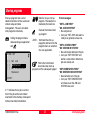
TPS300 Basic Series
User Manual TC(R)303/305/307
Version 3.5
English
Electronical Total Station
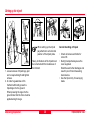
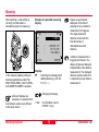
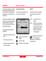
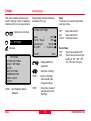
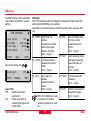
Symbols used in this manual
Congratulations on your purchase of a new Leica
Geosystems Total Station.
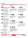
The symbols used in this User Manual have the following
meanings:
This manual contains important safety directions
(refer to section "Safety directions") as well as
instructions for setting up the instrument and
operating it. Please read this User Manual
carefully to achieve maximum efficiency from your
Instrument.
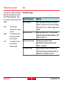
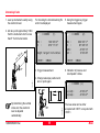
DANGER:
Indicates an imminently hazardous situation
which, if not avoided, will result in death or
serious injury.
WARNING:
Indicates a potentially hazardous situation or an
unintended use which, if not avoided, could result
in death or serious injury.
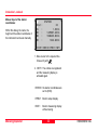
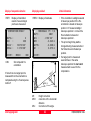
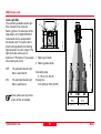
Product identification
CAUTION:
Indicates a potentially hazardous situation or an
unintended use which, if not avoided, may result
in minor or moderate injury and / or appreciable
material, financial and environmental damage.
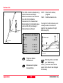
The type and the serial number of your instrument
indicated on the label in the battery compartment.
Write the type and serial number of your instrument in the
space provided below, and always quote this information
when you need to contact your agency or service
workshop.
Type:
Important paragraphs which must be adhered to
in practice as they enable the product to be used
in a technically correct and efficient manner.
Serial no.:
2
TC(R)303/305/307-3.5en
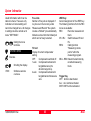
View of chapters
Introduction
TC(R)303/305/307-3.5en
7
Operating the Instrument
13
Measuring preparation
18
FNC Key
33
Start-up programs
37
Applications
43
Coding
67
Menu
71
Safety Directions
101
Care and Storage
115
Technical Data
124
Accessories
131
Index
132
3
View of chapters
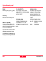
Contents
Introduction ................................................... 7
Measuring ................................................................. 30
Station block ................................................................... 31
Special features .......................................................... 7
Important parts ............................................................ 8
Technical terms and abbreviations ............................... 9
Area of applicability ..................................................... 11
PC Program Package Leica SurveyOffice .................. 12
FNC Key ....................................................... 33
EDM change .............................................................
REC (Storing) ............................................................
Height determination of remote points ........................
Laser Pointer .............................................................
Target Offset .............................................................
Delete last record ......................................................
Operating the Instrument ........................... 13
Keypad .....................................................................
Trigger key ................................................................
Buttons .....................................................................
Symbols ....................................................................
Menu tree ..................................................................
13
15
15
16
17
Start-up programs ....................................... 37
Setting job ................................................................. 38
Setting Station ........................................................... 39
Measuring preparation ................................ 18
Unpacking .................................................................
Inserting / replacing battery ........................................
Setting up the tripod ...................................................
Centring with laser plummet, coarse level-up .............
Accurate levelling-up with electronic level ...................
Laser intensity ...........................................................
Hints for Positioning ...................................................
Functions ..................................................................
Numerical input .........................................................
Known point .................................................................... 39
Set manually ................................................................... 39
18
19
20
21
22
22
23
24
25
Orientation ................................................................ 40
Method 1: Set orientation ................................................ 40
Method 2: Measure target points .................................... 41
Display of computed orientation ...................................... 42
Displaying residuals ........................................................ 42
Useful information ........................................................... 42
Applications ................................................. 43
Introduction ............................................................... 43
Surveying .................................................................. 44
Alphanumeric input ......................................................... 25
Point search ................................................................... 27
Wildcard search ............................................................. 29
Contents
33
33
34
35
35
36
4
TC(R)303/305/307-3.5en
Contents, contd.
Coding .......................................................... 67
Setting out ................................................................. 45
Setting out coordinates from memory ............................. 45
Manual input of setting out values .................................. 45
Polar setout .................................................................... 46
Orthogonal setout ........................................................... 46
Cartesian setout ............................................................. 46
Example ......................................................................... 47
Buttons ........................................................................... 47
Errors ............................................................................. 47
Menu ............................................................. 71
Quick Settings ........................................................... 71
Settings ..................................................................... 72
System Settings .............................................................. 72
Angle Settings ................................................................ 75
Unit settings .................................................................... 78
EDM Settings .................................................................. 79
Communication .............................................................. 83
Date and Time ................................................................ 84
Tie Distance .............................................................. 48
1. Polygonal Methods (A-B, B-C) .................................... 48
2. Radial Methods (A-B, A-C) .......................................... 50
Extended Display ............................................................ 51
Error ............................................................................... 51
System Information .................................................. 85
Data Manager ........................................................... 87
VIEW/EDIT DATA ........................................................... 87
Delete Memory ............................................................... 92
Data Download ............................................................... 93
Statistics ......................................................................... 94
Messages and Warnings ................................................ 95
Area computation ...................................................... 52
Free Station .............................................................. 54
Measuring facilities ......................................................... 55
Computation procedure .................................................. 56
Station setup .................................................................. 56
Measurements ................................................................ 57
Results ........................................................................... 58
Residuals ....................................................................... 59
Error messages .............................................................. 60
Determining instrument errors .................................... 96
Line-of-sight error (Hz-collimation) .................................. 97
V-Index (Vertical index error) .......................................... 97
Determining the line-of-sight error (c) .............................. 98
Determining V-index ....................................................... 99
Possible messages when determining instrument errors100
Reference Line .......................................................... 61
Definition of the Base Line .............................................. 61
Reference Line ............................................................... 63
Orthogonal Setout .......................................................... 65
Notes .............................................................................. 66
TC(R)303/305/307-3.5en
5
Contents
Contents, contd.
Safety Directions ....................................... 101
Checking and adjusting ............................................ 118
Tripod ........................................................................... 118
Circular level ................................................................. 118
Circular level on the tribrach ......................................... 118
Laser plummet .............................................................. 119
Reflectorless EDM ........................................................ 120
Intended use of instrument ...................................... 101
Permitted uses ............................................................. 101
Adverse uses ................................................................ 101
Limits of use ............................................................
Responsibilities .......................................................
Hazards of use ........................................................
Laser classification ..................................................
102
102
103
107
Battery charging ...................................................... 122
Technical Data ........................................... 124
Integrated distancer (infrared laser) ............................. 108
Integrated distancer (visible laser) ............................... 109
Guide Light EGL ........................................................... 110
Laser plummet ............................................................... 111
Atmospheric correction ............................................ 128
Reduction formulae ................................................. 130
Accessories ............................................... 131
Electromagnetic acceptability .................................... 112
FCC statement (applicable in U.S.) ........................... 114
Index ........................................................... 132
Care and Storage........................................115
Transport ................................................................. 115
In the field ..................................................................... 115
Inside vehicle ................................................................ 116
Shipping ....................................................................... 116
Storage .................................................................... 116
Cleaning ....................................................................... 117
Contents
6
TC(R)303/305/307-3.5en
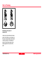
Introduction
Special features
The Leica Geosystems TC(R)303/
305/307 is a high-quality electronic
total station designed for the
construction site.
Its innovative technology makes the
daily surveying jobs easier.
• Easy and quickly to learn !
• Interactive keys; with large and
clear LCD.
• Small, light-weight and easy-touse.
The instrument is ideally suited for
simple construction surveys and
setting out tasks.
• Measurements without reflector
with the integrated visible laser
beam (TCR instruments).
The easy operation of the instrument
functions can be learned without
problems in no time.
• Additional trigger key on side
cover.
• Continuous drives for horizontal
and vertical angles (tangent
screws)
TC300z01
• With laser plummet as standard.
TC(R)303/305/307-3.5en
7
Introduction
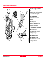
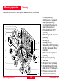
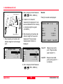
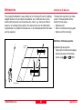
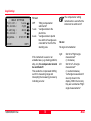
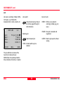
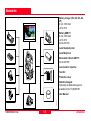
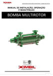
Important parts
10
11
Introduction
2
12
3
4
5
6
7
13
8
9
15 16 17 18
14
&
TC300Z02
1
1 Optical sight
2 Integrated guide light EGL (optional)
3 Vertical drive
4 Battery (optional)
5 Battery stand for GEB111
6 Battery cover
7 Eyepiece; focussing graticule
8 Focussing telescope image
9 Detachable carrying handle with
mounting screws
10 Serial interface RS232
11 Foot screw
12 Objective with integrated
Electronic Distance Measurement
(EDM); Beam exit
13 Display
14 Keyboard
15 Circular level
16 On/Off key
17 Trigger key
18 Horizontal drive
TC(R)303/305/307-3.5en
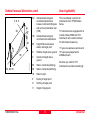
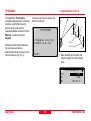
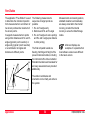
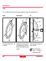
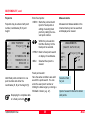
Technical terms and abbreviations
SA
SA
ZA = Line of sight / collimation
axis
Telescope axis = line from the reticle
to the centre of the objective.
ZA
V
ZA
SA = Standing axis
Vertical rotation axis of the
telescope.
KA
KA
KA = Tilting axis
Horizontal rotation axis of the
telescope (Trunion axis).
VK
V = Vertical angle / zenith angle
Hz0
KA
VK = Vertical circle
With coded circular division for
reading the V-angle.
Hz
HK
TC(R)303/305/307-3.5en
TC300Z24
SA
Hz = Horizontal angle
SA
9
HK = Horizontal circle
With coded circular division for
reading the Hz-angle.
Introduction
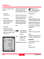
Technical terms and abbreviations, contd.
Standing axis
inclination
Angle between
plumb line and
standing axis.
Introduction
Line-of-sight
error (Hzcollimation)
The line-of-sight
error is the
deviation from
the perpendicular
between tilting
axis and line-ofsight. This could
be eleminated by
measuring in
both faces.
V-index
(Vertical index
error)
With horizontal
line-of-sight the
V-circle reading
should be exactly
90°(100gon).
The deviation
from this values
is termed Vindex (i).
TC300Z40
TC300Z39
TC300Z38
TC300Z13
i
TC300Z16
TC300Z37
c
Plumb line /
Compensator
Zenith
Reticle
Direction of
gravity. The
compensator
defines the
plumb line within
the instrument.
Point on the
plumb line above
the observer.
Glass plate
within the
telescope with
reticle.
10
TC(R)303/305/307-3.5en
Technical terms and abbreviations, contd.
SD
E, N, H
SD
hr
dH
hi
E0, N0, H0
TC(R)303/305/307-3.5en
TC300Z59
HD
Area of applicability
Indicated meteorological
corrected slope distance
between instrument tilting axis
and centre of prism/laser spot
(TCR)
HD
Indicated meteorological
corrected horizontal distance
dH
Height difference between
station and target point
hr
Reflector height above ground
hi
Instrument height above
ground
E0
Station coordinate (Easting)
N0
Station coordinate (Northing)
H0
Station height
E
Easting of target point
N
Northing of target point
H
Height of target point
11
This User Manual is valid for all
instruments of the TPS300 Basic
Series.
TC Instruments are equipped with an
invisible infrared EDM and TCR
Instruments with a visible red laser
for reflectorless measuring.
"J" types are Japanese versions and
"S" types are equipped with a
shiftable tribrach.
Sections only valid for TCR
instruments are marked accordingly.
Introduction
PC Program Package Leica SurveyOffice
The program package Leica
SurveyOffice is used for the data
exchange between the TPS300 and
the PC. It contains several auxiliary
programs in order to support your
use of the Instrument.
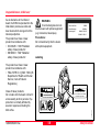
Installation on the PC
The installation program for the Leica
SurveyOffice can be found on the
CD-ROM supplied. Please note that
the Leica SurveyOffice can only be
installed under the operating systems
MS Windows 95/ 98, Windows 2000,
Windows NT4.0 and Windows ME .
For the installation call program
"setup.exe" in the directory
\SOffice\"Language"\Disk1 on the
CD-ROM and follow the input
instructions of the installation program. When using TPS300
instruments, select option "Standard"
or "User defined" and select TPS300
Tools additionally.
Introduction
Program content
After successful installation the
following programs appear:
• Data Exchange Manager:
For data exchange of coordinates,
measurements, codelists and
output formats between instrument
and PC.
• Codelist Manager:
For creating and processing of
codelists.
• Software Upload:
For loading/deleting system
software, application programs
and EDM-software as well as
system/application texts.
Before the Software Upload,
always insert a charged
battery into the instrument.
• Coordinate Editor:
Import/Export as well as creating
and processing of coordinate files.
12
• Settings:
For general settings of all
applications of Survey Office (e.g.
interface parameter).
• External Tools:
Access to Format Manager (userdefined output formats) and TPS
Setup (user-defined basic
settings). Here your output
software can be called directly, as
an example.
• Exit:
Quits the SurveyOffice.
• Register:
Registering type of instrument and
additional objects (e.g. formats) or
programs.
For more informationen
about Leica SurveyOffice
refer to the comprehensive Online
Help.
TC(R)303/305/307-3.5en
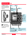
Operating the Instrument
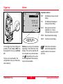
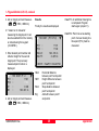
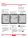
Keypad
The On/Off key is located on the
side cover of the TC(R)303/305/307
avoiding inadvertently switching the
Instrument off.
Buttons
Input bar
Focus bar
Actively processed field
or display key
8
913
1.70 0m
1
135°54'23"
2
RL
102°12'48"
3
----.--- 4m
<SETUP>
Navigation
keys
Control of input
bar in edit and
input mode or
control of focus
bar.
Fix keys - 2nd level
Functions on second key level. Can
be activated by pressing
and
the corresponding fix keys.
Fix keys
Keys with firmly assigned functions
(ENTER, SHIFT).
TC300Z25
PtID
hr
All shown displays are
examples. It is possible that
local software versions are different
to the basic version.
TC(R)303/305/307-3.5en
Symbols
Hz
V
HD
13
Operating the Instrument
Keypad, contd.
Fix keys
Measure distance and angle;
record measured values.
Measure distance and
angles; display measured
values without recording.
Key combinations
EDM ->
+
ESC ->
Access to distance measuring
functions and distance corrections
(ppm).
Key, programmable with
function from the FNC menu.
FNC ->
Calling the application
programs.
Quick-access to measurementsupporting functions.
Switching on/off electronic
level. The laser plummet is
activated simultaneously.
MENU ->
Switching to the second key
level (EDM, FNC, MENU,
illumination, ESC) and
switching between
alphanumeric/numeric
character set.
Erasing character/field;
stopping EDM.
Confirming an input; continue
to the next field.
Operating the Instrument
+
"Page Up" = scrolling upwards if
several displays available in one
dialog.
+
Access to Data Manager, instrument
settings and adjustments.
->
Quit a dialog or the edit mode with
activation of the "previous" value. Return to next heigher level.
PgUP->
+
+
+
PgDN->
+
"Page Down" = scrolling downwards
if several displays available in one
dialog.
Switching on/off the display
illumination and activating the display
heating (if instrument temperature
below -5°C).
14
TC(R)303/305/307-3.5en
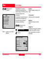
Trigger key
Buttons
PtID
hr
:
:
M13
1.600 m
Hz
V
HD
:
:
:
236°56'14"
91°12'23"
123.569 m
Important buttons :
SET
Set displayed value and quit
dialog.
OK
Set displayed message or
dialog and quit dialog.
EXIT
Early quit of a function/
application or a menu.
Changed values are not set.
PREV
Back to last active dialog.
NEXT
Continue to next dialog.
TC300Z63
<SETUP>
On the trigger key three settings are
possible. Function ALL or DIST can
be assigned to the key or switched
off.
The key can be activated in the
configuration menu (see "Menu/System settings").
TC(R)303/305/307-3.5en
<SETUP>
Buttons are a range of commands
appearing in the bottom line of the
display. They can be selected with
the navigation keys and activated
. Depending on the active
with
function/application other buttons
may become available.
15
Find further information
about menu/applicationspecific buttons in the relevant
sections.
Operating the Instrument
Symbols
Depending on software version different symbols are displayed indicating
a particular operating status.
A double arrow indicates
choice fields.
Using the navigation keys
the
desired parameter can be selected.
Choice fields can be quit with
as
well as with
or
.
, ,
Indicates that several pages
are available which can be
selected with
and
Status symbol "EDM type"
IR
Infrared EDM (invisible) for
measuring against prisms
and reflective targets.
RL
Reflectorless EDM (visible)
for measuring against all
targets.
.
I, II Indicates telescope position I
or II (refer also to "System
settings").
Indicates that Hz is set to "left
side angle measurement"
(anti-clockwise).
Status symbol "Battery capacity"
The battery symbol indicates
the level of the remaining
battery capacity (75% full
shown in the example).
Status symbol "Shift"
was pressed or
switching between
alphanumeric/numeric
character set.
Operating the Instrument
16
TC(R)303/305/307-3.5en
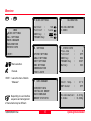
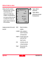
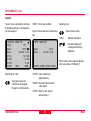
Menu tree
+
MENU
! QUICK SETTINGS
" ALL SETTINGS
# DATA MANAGER
$ CALIBRATION
% SYSTEM INFO
<EXIT>
Menu selection.
Execute.
<EXIT> Leave the menu. Back to
"Measure".
Depending on user interface
sequence and arrangement
of menu items may be different.
TC(R)303/305/307-3.5en
! QUICK SETTINGS
Contrast
:
Tilt Corr :
USER Key
:
TRIGGER Key:
"
50%
1-axis
IR-RL
ALL
CALIBRATION
HZ-COLLIMATION
V-INDEX
% SYSTEM INFO
SETTINGS
SYSTEM SETTINGS
ANGLE SETTINGS
UNIT SETTINGS
EDM SETTINGS
COMMUNICATION
TIME & DATE
#
$
DATA MANAGER
VIEW/EDIT DATA
INITIALIZE MEMORY
DATA DOWNLOAD
MEMORY STATISTIC
17
Free Jobs
Tilt Corr
USER Key
TRIGGER Key
Battery
:
:
:
:
:
3
OFF
REC
DIST
50%
Instr. Temp.
DSP Heater
:
:
21°C
OFF
Hz-Collimation:
V-Index
:
-0.015g
+0.008g
Operating the Instrument
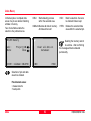
Measuring preparation
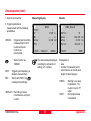
Unpacking
RemoveTC(R)303/305/307 from transport case and check for completeness:
TC300Z31
1
2
3
4
5
10
11
6
7
K ur
za
m öm
dl ko do
lm
ko ok ok
kj od ok
kd 9 oj
tu ng jk m di ük
lk
nl ei 30 0
dk
TC kl ko
kl ko
12
lk ok
8
13
9
14
15
Measuring preparation
18
1 PC cable (optionally)
2 Zenith eyepiece or eyepiece for
steep angles (optionally)
3 Counterweight for eyepiece for
steep angles (optionally)
4 Removable tribrach GDF111
(optionally)
5 Battery charger and accessories
(optionally)
6 Allen key (2x)
Adjusting pins (2x)
7 Spare battery GEB111(optionally)
8 Sun filter / plug adaptor tribrach
(optionally)
9 Mains unit for battery charger
(optionally)
10 Mini prism rod (optionally)
11 Total station
12 Mini prism + holder (optionally)
13 QuickStart Manual/ Mini target
plate (only for TCR instruments)
14 Protective cover / Lens hood
15 Tip for mini prism(optionally)
TC(R)303/305/307-3.5en
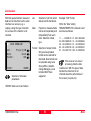
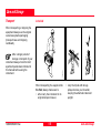
Inserting/ replacing battery
2. Remove battery and replace.
TC(R)303/305/307-3.5en
• For type of battery see chapter
"Technical Data".
• For charging battery see chapter
"Charging the batteries".
3. Insert battery into battery holder.
TC300Z06
TC300Z04
1. Remove battery holder.
TC300Z05
TC300Z03
Insert battery correctly (note
pole markings on the inside
of the battery cover). Check and
insert battery holder true to side into
the housing.
4. Insert battery holder into
instrument.
19
Measuring preparation
1.
1. 2.
2.
TC300Z19
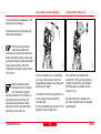
2.
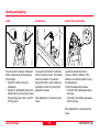
When setting up the tripod
pay attention to a horizontal
position of the tripod plate.
Heavy inclinations of the tripod must
be corrected with the footscrews of
the tribrach.
1. Loosen screws of tripod legs, pull
out to required length and tighten
screws.
2. In order to guarantee a firm
foothold sufficiently press the
tripod legs into the ground.
When pressing the legs into the
ground note that the force must be
applied along the legs.
Measuring preparation
20
TC300Z57
TC300Z33
1.
TC300Z32
TC300Z58
Setting up the tripod
Careful handling of tripod
• Check all screws and bolts for
correct fit.
• During transport always use the
cover supplied.
Scratches and other damages can
result in poor fit and measuring
inaccuracies.
• Use the tripod only for surveying
tasks.
TC(R)303/305/307-3.5en
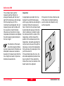
1. Place the instrument onto the
tripod head. Tighten central fixing
screw of tripod slightly .
2. Turn footscrews of tribrach into its
centre position.
3. Switch on laser plummet with
The electronic level appears in the
display.
TC(R)303/305/307-3.5en
4. Position tripod legs so that the
laser beam is aimed to the ground
point.
5. Firmly press in tripod legs.
6. Turn the footscrews of the tribrach
to centre the laser beam exactly
over the ground point.
21
TC300Z09
TC300Z08
TC300Z07
Centring with laser plummet, coarse level-up
7. Move the tripod legs to centre the
circular level. Now the instrument
is roughly levelled-up.
Measuring preparation
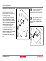
Accurate levelling-up with electronic level
Laser intensity
1. Switch on electronic level with
. In case of insuffient levellingup an inclined level symbol
appears.
Changing the laser intensity
If the electronic level is centered the
instrument is levelled-up.
External influences and the surface
conditions may require the
adjustment of the intensity of the
laser. As required, the laser plummet
can be adjusted in 25% steps.
20"
20"
20"
20"
2. By turning the footscrews centre
the electronic level.
3. Check centring with the laser
plummet and re-centring if
necessary.
4. Switch off the electronic level and
the laser plummet with
.
50% Max
5. With the <OK> button the
indicated laser intensity is set and
the function terminated.
Laser plummet and
electronic level are activated
together with
.
TC300Z10
Measuring preparation
Min.
22
TC(R)303/305/307-3.5en
TC300Z35
Hints for Positioning
Positioning over pipes or
depressions
Under some circumstances the laser
spot is not visible (e.g. over pipes). In
this case, the laser spot can be made
visible by putting on a transparent
plate. So the the laser spot can be
easily aligned to the centre of the
pipe.
TC(R)303/305/307-3.5en
23
Measuring preparation
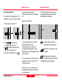
Functions
Input mode
Edit mode
Erasing characters
In the input mode erased fields are
filled with text or numerical values.
In the edit mode already existing
characters are overwritten, deleted or
changed.
• Method 1:
M
N
PRO
P
Q
N
O
PROP
R
S
1. Erase input field and
activate vertical input bar.
2. Select characters/numbers
in the input field.
3. Confirm selected
character. Character
moves to left.
C
D
PREP
F
G
M
N
PROP
P
Q
1. Start edit mode. Vertical
edit bar is positioned flush
right.
2. Edit bar is positioned flush
left.
3. Overwrite the relevant
character.
4. Erase a character.
4. Erase a character.
5. Confirm input.
5. Confirm input.
Measuring preparation
24
1. Place bar onto the character to be
erased.
2. Erase individual characters by
pressing
.
12345
1345
3. If all characters are erased the
previous value can be activated
again by pressing
once more.
• Method 2:
deletes the edited value
and restores the previous value.
TC(R)303/305/307-3.5en
Inserting characters
If a character was skipped (e.g. -15
instead of -125) you can insert it later.
Numerical input
Alphanumeric input
E.g. angle values, reflector,
instrument heights and coordinates,
etc.
A vertical bar appears in the active
input field containing alphanumeric
and additional characters.
Example: 350°49'30"
1. Place bar onto number "1".
9
0
-15
2
3
0
1
-125
3
4
2. With
a character is
inserted right of number "1".
3.
: Edit the inserted value
with the vertical edit bar.
4. Confirm input/change using
.
Hz:
2
3
4
350°49'30"
0
1
In case of inputs which are within
certain limits due to their
representation (e.g. angle unit
sexadecimal) the selection in the
vertical bar is automatically limited to
valid numbers.
As an example, if the angle unit "Sexagesimal" is set the entry of 370° is
not possible at all.
PtID:
P
Q
CORNER
S
T
U
Switch between numeric/
alphanumeric character set.
Selection of characters in the
input bar.
Mixed entries (numerical/
alphanumerical) are possible
into alphanumerical data fields.
After entry of "3" only numbers <6
are approved because entering 370
is not permitted.
TC(R)303/305/307-3.5en
25
Measuring preparation
Alphanumeric input, contd.
Character set
The vertical bar contains the following characters for the numeric/
alphanumeric input mode.
Numerical character set
"
"
"
"
+
.
0
"
"
"
-9"
(ASCII
(ASCII
(ASCII
(ASCII
43)
45)
46)
48 - 57)
Measuring preparation
Alphanumerical character set
"
"
"
"
"
"
"
"
"
"
"
"
"
"
"
"
(ASCII 32) [space]
!"
(ASCII 33)
#"
(ASCII 35)
$"
(ASCII 36)
%"
(ASCII 37)
&"
(ASCII 38)
*"
(ASCII 42)
+"
(ASCII 43)
-"
(ASCII 45)
."
(ASCII 46)
/"
(ASCII 47)
?"
(ASCII 63)
@"
(ASCII 64)
A - Z"(ASCII 65 .. 90)
_"
(ASCII 95) [Underscore]
26
Within data fields where point
numbers or codes can be searched
the character entry "*" is additionally
possible.
Signs
+/- In the alphanumeric character set
"+" and "-" are treated as normal
alphanumeric characters with no
mathematical function.
Additional characters
* Place holder during Wildcard point
search (see chapter "Wildcard
search").
"+" / "-" appears only in the
front position of an input.
In the edit mode the position
of the decimal place cannot
be changed. The decimal place is
skipped.
TC(R)303/305/307-3.5en
Point search
The point search is a global function
used by applications to search for
internally stored measuring points or
coordinates.
It is possible for the user to limit the
point search to a particular job or to
search the whole storage.
Job
:
PROJ_EAST
Fixed points are always displayed
first matching the relevant search
criteria. If several points meet the
search conditions then the points are
arranged depending on "age". The
instrument always finds the current
fixed point first.
TC(R)303/305/307-3.5en
Direct search
Definitions
By entering an actual point number
(e.g. "P13) all points with the
corresponding point number are
found.
FIXPT
Example:
Input: "P13"
As an example, 2 fixed points and 2
measurements are found. You can
page through the match selection
using
. As an example, a
possible sequence is shown below.
POINT SEARCH
5/20
Job :
PROJ_EAST
Pt
:
P13
E
:
128.400 m
N
:
244.000 m
H
:
2.500 m
Type :
FIXPOINT
<EXIT> <SEARCH>
<OK>
27
The point found is a fixed
point.
MEAS
The point found is a
measured point.
5/20
The point found is point
no. 5 of a total of 20
points in this relevant job.
Scroll within all points
matched.
<SEARCH> Re-enter the search
criteria.
If no suitable point can be
found the user is notified by
the error message "Point not found"
or "Database empty".
Measuring preparation
Point search, contd.
Point search is always started with
the last recorded point.
So the last entered/measured points
are displayed first; fixed points before
measured points.
Point number
Fixed points
P13, fixed point, time: 15:34:55
P13, measurement, time: 14:59:01
Point
found
first
P13, measurement, time: 15:46:12
P13, measurement, time: 16:18:38
P13
14:52:10
...
....
P13
15:34:55
...
....
...
...
....
....
...
....
P13 14:59:01
...
....
...
....
P13 15:46:12
P13 16:18:38
...
.....
P13, fixed point, time: 14:52:10
to start of list !
At the end of the measured
points the search returns to
the beginning ofthe fixed points.
Measuring preparation
....
TC300Z89
...
Scrolling through the list of
points found.
Found:
Time of recording
Measurements
28
TC(R)303/305/307-3.5en
Wildcard search
The Wildcard search is indicated by a
"*" . The asterisk is a place holder for
any following sequence of
characters.
Examples:
*
all points of any length are
found.
Wildcards are always used if the
point number is not fully known, or if
a batch of points is to be searched
for.
A
All points with exactly the
point number "A" are found.
A*
all points of any length
starting with "A" are found
(e.g.: A9, A15, ABCD)
*1
all points of any length with
a "1" at the second place
are found
(e.g.: A1, B12, A1C)
A*1
all points of any length with
an "A" at the first place and
a "1" at the third place are
found (e.g.: AB1, AA100,
AS15)
NEW SEARCH
Job :
PtID :
PROJ_4
S*
Starts point search.
TC(R)303/305/307-3.5en
Definitions
29
FIXPT
The point found is a fixed
point.
MEAS
The point found is a
measured point.
5/20
The point found is point
no. 5 of a total of 20
points in this relevant job.
Scrolling within all points
found.
<SEARCH> Re-enter the search
criteria.
Measuring preparation
Measuring
Example of a possible measuring
display:
TC300Z25
After switching on and setting up
correctly, the total station is
immediately ready for measuring.
In the measuring display calling all
functions/applications under FNC,
EDM, PROG, MENU, LIGHT, LEVELand LASER-PLUMMET is possible.
All shown displays are
examples. It is possible that
local software versions are different
to the basic version.
Measuring preparation
PtID
hr
:
:
M13
1.600 m
Hz
V
HD
:
:
:
236°56'14"
91°12'23"
123.569 m
<Hz0>
<SETUP>
Displays
Indicating more displays with
additional data (e.g. dH, SD,
E, N, H, ....)
Angles are permanently
displayed. At the time of
pressing the key a distance
measurement is triggered.
The angle values and
distance are stored in the
internal memory or
downloaded via serial
interface.
A distance measurement is
triggered and shown in the
display. Angles are displayed
independently of the distance
measurement. The displayed
distance remains valid until it
is replaced by a new distance
measurement.
: Changing the display.
<Hz0>
Hz-orientation is set to
0°00'00" / 0 gon.
30
TC(R)303/305/307-3.5en
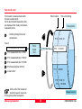
Station block
This dialog generates a station block
without coordinates which can be
evaluated by software.
In the data output the data is made
available depending on the
evaluation possiblities The orientation
is manual.
Procedure:
<SETUP> This button in the
measuring display activates
the definition of station and
orientation.
SETUP
StID :
hi
:
100
1.500 m
BsPt :
BsBrg:
101
0°00'00"
TC300Z79
<EXIT><Hz0> <STAT> <SET>
Station:
The station can be defined with a
station name.
1) Move cursor to "StID" and enter
station number as well as
instrument height "hi". Close entry
with
.
TC(R)303/305/307-3.5en
31
Orientation:
The orientation is designated again
with number and description of the
target point.
2) Move cursor to "BsPt" and enter
orientation point number. Close
entry with
.
3) Manual input of a Hz value as
orientation or set <Hz0>.
The orientation is continuously
displayed but can be modified in the
edit mode.
Buttons:
<Hz0> The Hz-angle is set to 0° or
0 gon.
<SET> The entries are registered
and the measuring display
is activated again.
<STAT> Starts manual input of the
station coordinates.
Measuring preparation
Station block , continued
Manual input of the station
coordinates:
Within this dialog, the name, the
height and the station coordinates of
the instrument can be set manually.
STATION
Stat
hi
E0
N0
H0
:
:
:
:
:
23
1.500
1475687.345
1693405.602
1243.932
m
m
m
m
<EXIT><ENH=0><PREV><SET>
1. Move cursor to the required line.
Close entry with
.
2. <SET>: The entries are registered
and the measuring display is
activated again.
<ENH=0> the station coordinates are
set to (0/0/0).
<PREV> Back to setup display.
<EXIT>
Measuring preparation
Back to measuring display
without saving
32
TC(R)303/305/307-3.5en
FNC Key
With "FNC" (
+
functions are available.
EDM change
) different
FUNCTIONS
IR<=>RL
RL
REC
REM. HEIGHT (REM)
LASERPOINTER
OFFSET
DEL.LAST REC. (DLR)
<EXIT>
Application of individual functions are
described in this chapter.
Functions can also be started directly
from the different applications.
Each function from the FNC
menu can be assigned to the
key (see chapter "Menu/
Settings").
TC(R)303/305/307-3.5en
REC (Storing)
Move cursor to EDM
selection (IR<=>RL).
Move cursor to REC function.
Start function.
Start function.
Change between the two EDM types
IR (Infrared) and RL (Reflectorless).
New setting is displayed for about
one second.
IR:
Infrared: Distance
measurements with prisms.
RL:
Visible laser: Distance
measurements without prisms
up to 80m; with prisms from
1 km up.
Actual measured data is stored by
"REC" to the internal memory or via
the serial interface.
By activating "REC" the following
actions are carried out:
• Recording a measurement block.
• Incrementing of current point
number.
Find more information in chapter
"EDM Settings".
!!
FNC Key
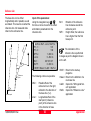
Height determination of remote points
Move cursor to "REM.
HEIGHT (REM)" function.
Start function.
Measure base point:
Determine remote point:
1. Enter point number and prism
height.
3. Aim at the remote point with the
telescope .
BASE POINT Pt1
Remote point
TC300z15
Slope
e
distanc
Height diff.
Pt1
Hr
HD
:
:
:
BH001
1.650 m
----.--- m
<EXIT>
<MEAS>
2. Trigger distance measurement and
indication of horizontal distance
(HD) with <MEAS>.
Base point
<MEAS> Measure and record the
base point.
Points directly above the base prism
can be determined without a prism at
the target point.
Pt1
Pt2
dH
H
HD
BASE POINT Pt2
:
100
:
101
:
8.346 m
:
512.042 m
:
70.571 m
<EXIT> <NEWBASE>
<MEAS>
4. Store with "MEAS" measured data
of the remote point. No new
distance measurement is carried
out.
Height (H) and height difference (dH)
as function of actual V-angle and
measured distance to base point are
computed and displayed immediately.
<NEWBASE> Enter and measure a
new base point.
FNC Key
!"
TC(R)303/305/307-3.5en
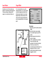
Laser Pointer
Target Offset
Switches on or off the visible laser
beam for illuminating the target point.
The new setting is displayed for
approx. one second and then set.
If it is not possible to set up the
reflector directly, or it is not possible
to aim the target point directly, the
offset values (length, cross and/or
height offset) can be entered. The
values for the angle and distances
are calculated directly for the target
point.
Measurement
Point
Offset PT.
Of
fs.
Ln
Of
fs.
gth
Ln
-
gth
+
Offs.Cross -
Elev. +:
Offset point is
higher than
measurement
TC(R)303/305/307-3.5en
!#
TC300Z96
Offs.Cross +
3D OFFSET
PtID
:
23
hr
:
1.500 m
L_Offset : 2.200 m
T_Offset : 3.660 m
H_Offset : 1.780 m
Mode:
Permanent
<EXIT>
<SET>
Procedure:
1. Enter the point ID and the reflector
height
2. Enter the offset values (length,
cross and/or height) as per the
sketch
3. Define the period for which the
offset is to apply.
4. <SET> calculates the corrected
values and jumps to the
application from which the offset
function was started. The
corrected angle and distances are
displayed as soon as a valid
distance measurement has been
triggered or exists.
FNC Key
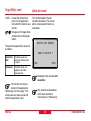
Target Offset, contd.
Delete last record
<EXIT> Leaves the function and
returns to the application
from which the function was
started.
Changes to 2D target offset
(without entry of the height
offset).
This function deletes the last
recorded data block. This can be
either a measurement block or a
code block.
DELETE LAST RECORD
The period of applicability can be set
as follows:
SURE TO DELETE ?
Reset after
REC
The offset values are
reset to 0 after the point
is saved.
Permanent
The offset values are
applied to all further
measurements.
<NO>
<YES>
Deleting the last record is not
reversible !
The function can only be
started in the applications
"Measuring" and "Surveying". The
offset values are always reset to 0
when the application is quit.
FNC Key
Only records can be deleted
which were recorded in
"Surveying" or in "Measuring".
!$
TC(R)303/305/307-3.5en
Start-up programs
Start-up programs are a set of
sidekick functions for the successful
stations setup and data
management. The user can select
start programs individually.
Calling the program menu
and executing an application
with
.
Select or skip a start-up
program. The selection is
marked by the black bar.
Execute the marked startup program.
<EXIT> Terminate the start-up
programs and back into the
program menu or selection
of a new application.
STAKE OUT
[_]
[_]
[ ]
Set Job
SetStation
Set Orientation
Stakeout
Find further information
about individual start-up
programs on the subsequent pages !
<EXIT>
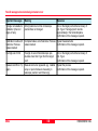
Error messages:
"SET A JOB FIRST"
"NO JOB IN SYSTEM"
• No valid job set.
> Carry out "SET JOB" and select a
valid job or generate a new one.
"SET A STATION FIRST"
"NO STATION IN SYSTEM"
• No valid station defined in the job.
> Carry out "SET STATION" and
define a valid station. Note that a
job was already set.
"SET ORIENTATION FIRST"
"NO ORIENTATION IN SYSTEM"
• No orientation set in the job.
> Carry out "SET ORIENTATION"
and make sure that JOB and
STATION are valid.
A "•" indicates that a job is set and
that in the job set the last station/
orientation in the memory correspond
to the actual station/orientation.
TC(R)303/305/307-3.5en
!%
Start-up programs
Setting job
All data is saved in JOBS, like
directories. Jobs contain
measurement data of different types
(e.g. measurements, codes, fixed
points, stations,...) and are
individually manageable and can be
readout, edited or deleted separately.
If a job was not yet defined and
or REC is activated in "MEASURE"
the system automatically generates a
job with name "DEFAULT".
Using the SurveyOffice program
package TPS300 Tools "TPS setup"
the number of available jobs can be
either set to 4 (mixed data
management: measurements and
fixed points) or to 8 (only
measurements or only fixed points).
Remarks
1/2
Re-enter Job
Job no 1 of a total of two
available jobs.
<NEW> Defining a new job.
Activates a display for input
of a new job name and
user.
<SET>
SELECT JOB
Job :
User:
DATE:
TIME:
<EXIT>
1/2
Project_A05
R.FISCHER
04/07/1998
16:42
<NEW>
<SET>
Setting the job and
continue to "SET STATION".
<EXIT> Back to start-up programs.
All subsequent recorded data
is stored in this job/directory.
Date and time are
automatically placed by the
system and cannot be
changed.
Selection
Using the arrow keys you can scroll
within the available jobs. Select the
desired job.
Start-up programs
38
TC(R)303/305/307-3.5en
Setting Station
Known point
Each coordinate computation relates
to the currently set station.
Therefore, at least station point plan
coordinates (E, N) are required. The
station height can be entered
optionally. The coordinates can be
entered either manually or read from
the internal memory.
H
E0
TC300z86
N
N0
E
Set manually
SET STATION
Stn :
200
hi
:
1.600 m
E0
:
N0
:
H0
:
<EXIT>
1000.000 m
1000.000 m
1000.000 m
<SET>
1. Enter a point number available in
the memory or point search with
Wildcard (*).
If an entered point number cannot be
found in the internal memory then the
manual input is activated
automatically.
1. Enter Point ID.
2. Enter coordinates and height.
3. <OK> : Sets and records station
coordinates. Return to "SET
STATION".
2. <SET>
Sets and records station
coordinates. Return to start program overview.
3. Wildcard-Search enables the
global search for points in the
complete memory (all jobs).
: Extends the display.
TC(R)303/305/307-3.5en
39
Start-up programs
Orientation
Method 1: Set orientation
This program enables an orientation
angle to be entered manually, or for
the orientation to be determined by
measurement to points with known
coordinates.
Set any Hz-orientation
Set Hz0
By entering the Hz-angle the user
can set any Hz-orientation.
Using button <Hz0> the orientation
can be set to 0.000 quickly and
easily.
Orientation coordinates can be either
obtained from the internal memory or
entered manually. Using button
<Hz0> the orientation can be set to
0.000 quickly and easily.
The system offers the following
possibilities:
• Setting any Hz-value with manual
input.
• With <Hz0> set Hz=0.000.
• Orientation to target points with
known coordinates.
Start-up programs
ORIENTATION
(set new or confirm)
BsPt :
BsBrg :
101
0°00'00"
<EXIT><Hz0> <COORD><SET>
Move cursor to input field
"BsBrg".
Enter new angle.
<Hz0>
<SET>
Hz-orientation is set to
0°00'00".
Orientation is confirmed if
no input was made, or the
new orientation is set and
registered if a new point
number was entered or a
new Hz-angle set.
Optionally, an alphanumeric
point number and a
description can be added to the
orientation block.
Erase field or set to 0°00'00".
40
TC(R)303/305/307-3.5en
Method 2: Measure target points
For determining the orientation a
maximum of 5 target points with
known coordinates can be used.
<COORD> Activates input/edit mode
for entry of a known
orientation point.
1/I
1/I II
3. Target point
Hz
=0
2. Target point
TC300z14
Hz1
ORIENTATION 1/I II
BsPt :
201
hr
:
1.300 m
BsBrg:
236°56'14"
dHz :
51°12'23"
dHD :
0.569 m
<MEAS>
1. Target point
MEAS:
Orientation coordinates can be either
obtained from the internal memory or
entered manually.
If an orientation point number cannot
be found in the internal memory then
the instrument automatically activates
the manual entry of the coordinates.
TC(R)303/305/307-3.5en
Dialog for orientation to
several target points.
41
dHz:
After the first
measurement the
finding of other target
points (or the same
point when changing
the telescope position)
is easier by setting the
indicated angle
difference near to
0°00'00" by turning the
instrument.
dHD:
Difference between
horizontal distance to
target point computed
from coordinates and
the measured
distance.
<SET>
An angle and a distance
measurement is triggered.
If no distance can be
measured only an angle
measurement is made.
Status indication;
shows that first point
was measured in
telescope position I.
First point measured in
telescope pos. I and II.
Start-up programs
Display of computed orientation
Displaying residuals
Useful information
<SET>
<RESI> Display of residuals.
• If the orientation is only measured
in telescope position II the Hzorientation is based on telesope
position II. If measured only in
telescope position I or mixed the
Hz-orientation is based on
telescope position I.
• The prism height may not be
changed during measurements in
the first and second telescope
position.
• If a target point is measured
several times in the same
telescope position the last valid
measurement is used for the
computation.
Display of orientation
results if several target
points are measured.
ORIENTATION RESULT
<EXIT>
<OK>
2
200
123°00'23"
± 0°00'08"
<RESI>
<OK>
Set computed Hzorientation.
<EXIT>
If more than one target point is
measured then the orientation is
computed using the "least squares
method".
actual
dH
dO
dHz (+)
ffs
D(
(+
-)
)
design
dH:
dHD:
dHz:
Start-up programs
<OK>
TC300z80
NoPts.:
Stn
:
HzCor :
StDev :
RESIDUALS Pt: 1/3
BsPt :
ABC1
dHz :
-0°00'23"
dHD :
-0.045 m
dOffs:
-0.028 m
dH
:
0.075 m
Height correction
correction of the horizontal
distance
Correction of Hz-angle.
42
TC(R)303/305/307-3.5en
Applications
Depending on local software
versions the contents of the
displays (lines) described in this
chapter can differ. However, the
function of the relevant display
remains the same.
Before starting an
application, make sure the
instrument is perfectly levelled up
and the station data is correctly set.
Introduction
With these onboard applications the
functionality of the TC(R)303/305/307
instruments are improved
considerably.
As a result, the functionality is extended and the daily surveying fieldwork
is made easier. By using internally
recorded values the user is mainly
protected from entering incorrect
data. Points with given coordinates
as well as measured points can be
used within the programs.
Distance measurement is
triggered.
ALL :
Values are measured and
recorded.
TC(R)303/305/307-3.5en
PROGRAM
1 SURVEYING
2 SETTING OUT
3 TIE DISTANCE
4 AREA (PLAN)
5 FREE STATION
6 REFERENCE LINE
<EXIT>
The following programs are available
in the internal memory:
Selecting the desired
application.
•
•
•
•
•
•
Calling the application and
activating the start
programs.
Button functions
DIST:
Calling the program menus.
Surveying
Setting Out
Tie Distance
Area
Free Station
Reference Line
43
When starting an application
the dialog with the start-up
programs is called automatically
(see chapter "Start programs").
Applications
Surveying
With the program Surveying the
measuring of an unlimited number of
points is supported. The program can
be compared to simple measuring.
Only the guided stationing or
orientation (see chapter "Start
programs") and the additional display
for target coordinates are different.
Procedure:
Measuring display 1
1. Input of point number.
2. Input of code, if required (see also
"CODING")
3. Enter new reflector height or
change the existing height.
4. Trigger and record measurements
,
with
assigned).
or
(if REC is
TC300z48
Find further information
about coding in chapter
"CODING".
With
/
you can switch
quickly and easily between different
displays.
Measured data can either be
recorded in the internal
memory or output via serial interface
RS232 (see configuration / Interface
parameter).
Applications
SURVEYING
PtID :
AB-12
hr
:
1.600 m
Code :
Baum
Hz
:
123°12'34"
V
:
79°56'45"
SD
:
412.883 m
<EXIT>
Measuring display 2
Hz
:
HD
:
dH
:
<EXIT>
Measuring display 3
E
:
N
:
H
:
<EXIT>
44
123°12'34"
406.542 m
72.081 m
1739.420 m
932.711 m
456.123 m
TC(R)303/305/307-3.5en
Setting out
Setting out coordinates from memory
Manual input of setting out values
The application computes setting-out
elements for the polar, cartesian or
orthogonal setting out of points
using either coordinates or manually
entered angle, horizontal distance
and height. Setting out differences
can be displayed continuously.
In the Setting out program three different displays are available showing
setting out values corresponding to
the relevant method.
1. Input of a point number.
If the desired point number could
not be found the system opens the
manual coordinate entry
automatically.
1. Enter direction (Brg), horizontal
distance (Hdis) and height (H) of
setout point.
Switching display and
method.
With the input of a Wildcard search
criteria (*) all relevant points can be
found quickly and easily by simply
scrolling through with
/
.
Additionally, the type of the point
found (fixpoint or measured point) is
displayed.
TC(R)303/305/307-3.5en
2D SET OUT
PtID :
Dist :
dHz :
dHD :
<EXIT>
<B&D>
P1*
P100
Fixpoint
10.200 m
30°25'14"
4.782 m
<B&D>
Instrument is switched to
"Manual input of setting out
values".
Changing to 3D set out.
BEAR & DIST ENTRY
PtID
Brg
Hdis
H
:
:
:
:
<EXIT>
ABC1
123°12'36"
123.569 m
12.456 m
<PREV>
<SET>
2. <SET> : The entered data is set.
Calling the setting out dialog.
3. Trigger measurement with
or
.
4. The setout offsets are displayed in
the same way as with the polar
setout.
<PREV> Changing to 2D/3D setting
out (ref. to section "Setting
out coordinates from
memory").
45
Applications
Polar setout
Orthogonal setout
Cartesian setout
Normal indication of polar setout
offsets dHz, dHD, dH.
The position offset between
measured point and setout point is
indicated in a longitudinal and transversal element.
Setting out is based on a coordinate
system and the offset is divided into a
north and east element.
Actual
Actual
+dHz
+d
H
D
dH:
Angle offset: positive if
point to be setout is to the
right of the actual direction.
Longitudinal offset: positive
if point to be setout is further away.
Height offset: positive if
point to be setout is higher
than measured point.
Applications
dL:
dT:
+dN
+dL
Longitudinal offset: positive
if nominal point further
away.
Transversal offset,
perpendicular to line-ofsight: positive if nominal
point is to the right of
measured point.
46
Actual
+dE
TC300z47
TC300z41
dHD:
N
+dT
dHz
dHz:
point to be
setout
point to be
setout
TC300z42
point to be setout
E
dE
dN
Easting offset between setout and actual point.
Northing offset between
setout and actual point.
TC(R)303/305/307-3.5en
Example
Buttons
Errors
By entering a Wildcard criterion (*) a
group of points can be found easily
and set out one after the other.
With
in the "PtID" field point data
are displayed and scrolled.
No or invalid PtId or coords:
• The point number entered is not
available.
> Re-enter point number/
coordinates.
2D SET OUT
PtID :
Dist :
dHz :
dHD :
dH
:
<EXIT>
Input:
Finds:
P1*
P100
10.200 m
30°25'14"
4.782 m
0.411 m
<B&D>
C1*
C10
C11
C12
...
FIND POINT 3/6
Job :
Proj_A4
PtID :
C12
E
:
735.482 m
N
:
633.711 m
H
:
141.581 m
Type :
FIXPOINT
<EXIT> <FINDPT>
<OK>
Invalid entries of data:
• Manually entered setting out data
is incomplete (e.g. setting out
distance missing).
> Check setout parameter and reenter.
<EXIT> Quit application "Setting
out". Return to "Measure".
<FINDPT> Re-enter the search
criteria.
Using
you can page quickly
through the points found.
TC(R)303/305/307-3.5en
47
Applications
Tie Distance
Distances and directions between
two successive points are
determined and can be saved in the
internal memory (e.g 3 to 4).
0'0
°0
=0
TIE DISTANCE
Az 1-2
T101
T202
1 Polygonal (A-B, B-C)
2 Radial (A-B, A-C)
dSD 2-3
<EXIT>
Az 2-3
dSD 1-2
T303
1. Enter desired point number and
reflector height for the first target
point.
Pt1
hr
HD
Applications
0''
N
Hz
The user can choose between two
different methods:
TC300Z85
The application Tie Distance
computes slope distance, horizontal
distance, height difference and
azimuth of two target points
measured online, selected from the
Memory or entered using the
Keypad.
1. Polygonal Methods (A-B, B-C)
48
TIE DISTANCE PT 1
:
T101
:
1.300
:
102.501 m
TC(R)303/305/307-3.5en
1. Polygonal Methods (A-B, B-C), continued
2. Aim on target point and measure.
(
,
/ REC, <MEAS>)
2.1 Variant on 2: instead of
measuring the target point, it can
also be selected from the memory
or entered using the keypad.
(<COORD>)
3. Enter desired point number and
reflector height for the second
target point. The previously
measured point number is
displayed.
Pt1
Pt2
hr
HD
TIE DIST PT 2
:
T101
:
T102
:
1.300
:
102.501 m
Results
Finally, the results are displayed.
TIE DIST (Pt1-Pt2)
Pt1 :
Pt2 :
Hdist:
Hdiff:
TC(R)303/305/307-3.5en
<NextPt2> Point 2 is set as starting
point of a new missing line.
New point (Pt 2) must be
measured.
<EXIT> <NewPt1><NextPt2>
Hdist
Hdiff
Sdist
Brg
4. Aim on target point and measure.
(
,
/ REC, <MEAS>)
T101
T102
124.145 m
2.678 m
<NewPt1> An additional missing line
is computed. Program
starts again (at point 1).
Horizontal distance
between point1 and point2.
Height difference between
point1 and point2.
Slope distance between
point1 and point2.
Azimuth between point1
and point2.
49
Applications
TC300Z103
2. Radial Methods (A-B, A-C)
2. Aim on target point and measure.
(
,
/ REC, <MEAS>)
Slope distance 1-2
'
N
00'
Az 1-3
00'
=0°
Hz
Az 1-2
Slope
distance 1-3
Finally, the results are displayed.
2
Az 1-4
1
Centre
point
3
4
Slope distance 1-4
1. Enter desired point number and
reflector height for the first target
point.
Pt1
hr
HD
CENTRE POINT
:
15
:
1.600
:
--.--- m
Results
2.1 Variant on 2: instead of
measuring the target point, it can
also be selected from the memory
or entered using the keypad.
(<COORD>)
3. Enter desired point number and
reflector height for the second
target point. The previously
measured point number is
displayed.
Pt1
Pt2
hr
HD
RADIAL POINT
:
15
:
16
:
1.600
:
--.--- m
RADIAL DIST (1-2)
Pt1 :
Pt2 :
Hdist:
Hdiff:
15
16
2.359 m
1.003 m
<START> <NewCP> <NextRP>
<NewCP>
Measure new centre
point. Program starts
again (at point 1).
<NextRP>
Measure new radial
point (centre point Pt. 1
is retained)
4. Aim on target point and measure.
(
,
/ REC, <MEAS>)
Applications
50
TC(R)303/305/307-3.5en
Extended Display
Error
On the measurement of the target
points and when displaying results,
additional angle and distance
information can be displayed.
Error message
"No Distance measured"
• Distance measurement has not
been carried out or not saved.
> Make the measurement again.
Pt1
hr
HD
TIE DIST PT 1
:
T101
:
1.300 m
:
102.501 m
Changes between displays
shown above and below.
Pt1
hr
Hz
V
HD
TIE DIST PT 1
:
T101
:
1.300 m
:
222°45'42"
:
87°30'55"
:
102.501 m
<EXIT>
TC(R)303/305/307-3.5en
<MEAS>
51
Applications
Area computation
From three measured points the
actual area is computed and
displayed on-line. By activating
<RESULT> the number of points
used, the computed area and the
closed polygonal length (e.g. line 1-23-4-1) are displayed.
Polygonal length, from
starting point to the
actual measured point.
TC300z34
The application areas (plane)
computes online areas from an
unlimited number of points connected
by straights.
2
3
Start
1
4
The points can be measured
optionally in the first or second telescope position/face.
Between the individual points the
telescope position/face can be
changed. One distance must always
be measured.
Applications
5
Actual area, always
closed to the starting
point (1).
52
TC(R)303/305/307-3.5en
Area computation, contd.
1. Input of point number.
2. Triggering a distance
measurement with the following
possibilities:
<MEAS>
Triggering and recording
a measurement. Point
counter and point
number are
incremented.
Same function as
<MEAS>.
DIST/
REC
Measuring display
AREA
PtID
hr
HD
Area
Pts
:
:
:
:
:
AREA_Result
1
1.500 m
---.-- m
0.000 m2
1
<EXIT> <RESULT>
<MEAS>
The area is always displayed
according the onboard unit
setting ( m², hectare).
Triggering and displaying a
distance measurement.
Saving with REC if key
is assigned accordingly.
NoPts
Area
Area
Perim
15
148.472 m2
0.014 ha
65.241 m
<NEW>
Displayed are:
• area
• number of measured points
• circumference of closed area/
length of closed polygon.
<EXIT>
53
:
:
:
:
<EXIT>
<NEW>
<RESULT> Recording of areas,
circumference and point
counter.
TC(R)303/305/307-3.5en
Results
Starting a new area
computation. The
counter is set to "0"
again.
Quit program area
computation.
Applications
Free Station
The application "Free Station" is used
to determine the instrument position
from measurements to a minimum of
two known points and a maximum of
five known points.
It supports measurements to points
using either distances and Hz- and Vangles (typical 2 point resection) or
angles only (typical 3 point resection)
or a combination of angles and
distances to different points.
H
N
The following measurements
sequences to target points are
possible:
1. Hz- and V-angles only
2. Distance and Hz- and V-angle
3. Hz- and V-angles to some point(s)
and Hz- and V-angle plus distance
to other point(s).
The final computed results are
Easting, Northing and Height of the
present instrument station, including
the instruments Hz-circle orientation.
Standard deviations and residuals for
accuracy assessments are provided
additionally.
Measurements and results (position,
standard deviations and residuals)
are always recorded to the internal
memory, provided the internal
memory is set as the Data Storage
media.
All shown displays are
examples. It is possible that
local software versions are different
to the basic version.
TC300z90
The station coordinates and
orientation can be finally set active to
the system.
Applications
E
54
TC(R)303/305/307-3.5en
Measuring facilities
Single face I or II or dual face I + II
measurements are always possible.
No specific point sequence or
specific face sequences are required.
Any point can be measured with any
face at any time prior of starting the
computation process, e.g. measure
the last point first - then the first point
- and then the second point - etc…
If a target point is measured
several times in the same
telescope position the last valid
measurement is used for
computation.
Gross errors checks are made for
dual face measurements to ensure
the same point(s) are sighted with
the other face.
Measurement restrictions:
• 2 face measurements
For measurements in 2 faces, the
reflector height and the refraction
coefficient must be kept the same
for both faces for the same target
point, although it is permissible to
change them between different
target points. An error message
will be generated if the reflector
height changes between face I and
face II while measuring to the
same target point.
• Target points with 0.000 height
Target points with 0.000 height are
discarded for height processing. If
target points have a valid height of
0.000 m, use 0.001 m to enable it
for height processing.
TC(R)303/305/307-3.5en
55
Applications
Computation procedure
The computation process
automatically determines the
processing method, e.g. 2 point
resection, 3 point resection with
angles only, etc…)
If more than the minimum required
measurements are performed, the
processing routine uses a least
squares adjustment to determine the
plan position and averages
orientation and heights.
1. The original averaged face I and
face II measurements enter the
computation process. In case of
multiple measurements to the
same target point, only the last
measurement for each face enter
the computation process.
Station setup
3. The final plan position (E, H) is
computed from a least squares
adjustment, including standard
deviations and residuals for Hzangle and horizontal distances.
Procedure:
1. Enter the station name (Stn)
2. Enter the instrument height (hi)
4. The final height (H) is computed
from averaged height differences
based on the original
measurements.
5. The Hz-circle orientation is
computed with the original
averaged face I and face II
measurements and the final
computed plan position.
FREE STATION
(Station Setup)
Stn
hi
:
:
<EXIT>
PEG1
1.567 m
<OK>
<OK>
Proceeds to the
measurement screen.
<EXIT> Terminate and return to the
start-up program.
2. All measurements are treated with
the same accuracy, whether these
are measured in single or dual
face.
Applications
Set the occupied station name and
instrument.
56
TC(R)303/305/307-3.5en
Measurements
Free Station methods:
• 2 point resection
=> always use the
-key or
the Button <MEAS>
• 3 point resection with angles
only
=> Always use the REC-command
under the FNC-menu or the
key if REC is assigned to it.
• Mix of distances and angles
=> Use either
-key or the Button <MEAS> for distances and
angles or REC-command for
angles only.
Procedure:
1. Enter the target point number
(PtID).
If the desired point is not found
within the internal memory, the
system automatically opens the
manual coordinate entry.
TC(R)303/305/307-3.5en
2. Enter the reflector height (hr).
FREE STATION 1/I II
PtID :
ABC1
hr:
2.300 m
Hz:
236°56'14"
V:
91°12'23"
SD:
123.569 m
<EXIT>
<CALC>
<MEAS>
<MEAS> Button initiates
measurements.
a) If the target is a prism the Hz- and
V-angles and distance is
automatically measured and
recorded
b) If the target is not a prism or the
reflectorless EDM cannot measure
a distance, only Hz- and V-angles
are measured and recorded
The ALL-key measures and
records the Hz- and Vangles and the distance.
REC
<CALC> Proceeds with the result
screen and computes the
instrument position if at
least 2 points in single face
with at least one distance
are measured
<EXIT> Terminate and return to the
start-up program.
1/I
1/I II
57
The REC-command (refer
to FNC) measures and
records only Hz- and Vangles
Status indication; shows
that first point was
measured in telescope
position I.
Shows that first point was
measured in telescope
position I and II.
Applications
Results
This dialog shows the final computed
station coordinates and instrument
height.
1. Page (viewing the station
coordinates and instrument height)
FREE STATION RESULT
Stn:
PEG1
E :
14757687.345 m
N :
16934025.602 m
H :
1243.932 m
hi :
1.576 m
<SET>
Sets the displayed
coordinates and instrument
height as the final station to
the system.
<RESID>Moves to the residual
screen.
<PREV> Returns to the measuring
screen for more points to
measure.
<EXIT> Terminates the application
"FREE STATION" without
setting the new station data
to the system.
If the instrument height was
set to 0.000 in the setup
screen, then the station height refers
to height of trunnion axis.
<EXIT><PREV><RESID><SET>
Stn
E
N
H
hi
= Name of occupied station
= Computed station Easting
= Computed station Northing
= Computed station Height
= Instrument height
Applications
58
TC(R)303/305/307-3.5en
Results, contd.
2. Page (viewing standard deviations)
FREE STATION RESULT
Pts
:
2
s.Dev E :
0.012 m
s.Dev N :
0.120 m
s.Dev H :
0.035 m
s.DevAng :
0°00'23"
<EXIT><PREV><RESID><SET>
Residuals
<SET>
Sets the displayed
coordinates and instrument
height as the final station to
the system
<RESID>Moves to the residual
screen
<PREV> Returns to the measuring
screen for more points to
measure.
<EXIT> Terminates the application
FREE STATION without
setting the new station data
to the system.
Pts
= Number of measured
points
s.Dev E = Standard deviation Station Easting
s.Dev N = Standard deviation Station Northing
s.Dev H = Standard deviation Station Height
s.DevAng = Standard deviation circle
orientation
TC(R)303/305/307-3.5en
This dialog shows the computed
residuals.
The residuals always show computed
value (given data) minus measured
value.
RESIDUALS
1/3
PtID:
ABC1
dHz :
-0°00'23"
dHD :
-0.045 m
dH :
0.075 m
<EXIT>
<PREV>
<PREV> Returns to the result screen
<EXIT> Terminates the application
FREE STATION without
setting the new station data
to the system.
Use the
cursor keys
to toggle the display of
residuals for the various
measured points.
59
Applications
Error messages
Important messages
Meaning
Selected point has no valid data
This message occurs if the selected target point has no easting or northing
coordinate
Max 5 points supported
If already 5 points are measured and a further point is selected . The system
supports maximum 5 points
Bad data - no position computed
The measurements may not allow to compute final station coordinates (Easting,
Northing)
Bad data - no height computed
Either the target height are invalid or insufficient measurements are available to
compute a final station height.
Insufficient space in job
The present selected job is full and does not allow further storage. This error
could occur either with measurements or when the system stores result data,
such as station results. standard deviations or residuals.
Hz (I - II) > 0.9 deg, measure point
again
This error occurs if a point was measured in one face and the measurement in
the other face differs by more than 180° ±0.9° for the horizontal angle circle
V (I - II) > 0.9 deg, measure point
again
This error occurs if a point was measured in one face and the measurement in
the other face differs by more than 180° ±0.9° for the vertical angle reading
More points or distance required
There are insufficient data measured to be able to compute a position. Either
there are not enough points used or not enough distances measured.
Applications
60
TC(R)303/305/307-3.5en
Reference Line
Definition of the Base Line
This program facilitates the easy setting out or checking of lines for buildings,
straight sections of road, simple excavations, etc. A reference line can be
defined with reference to a known base line, which, e.g. has been defined
based on an existing site boundary. The reference line can be offset either
longitudinally or in parallel to the base line, or be rotated around the first base
point as required.
The base line is given by two base
points. The base points can be
defined in three ways:
• Measure point
• Enter co-ordinates using keypad
• Select point from memory.
Definition of the base points:
N
2nd base
point
TC300Z98
en
fer
Re
Ba
se
ce
lin
lin
e
e
a) Measuring base points:
Input a point number and independent measurement of the base
points using
or
/ REC.
1st base point
TC(R)303/305/307-3.5en
61
Applications
Definition of the Base Line, continued
b) Base points with co-ordinates:
Input a point number. The search
for associated points in the
memory can be initiated using
<COORD>. If the required point is
not in memory or there are no valid
co-ordinates in the memory, the
program prompts for manual entry
of the co-ordinates.
Analogous procedure for the second
base point.
Applications
Define Baseline Pt.1
PtID:
101
hr :
1.600 m
Hz :
V
:
HD :
<EXIT>
236°56'14"
91°12'23"
15.457 m
<COORD>
Triggers a distance
measurement.
Triggers a distance
measurement and register
the measured data.
<EXIT>
Return to the start-up
programs.
<COORD> Input co-ordinates or
search for fixed points
and measurements.
<FINDPT> Activates selective point
search (see "Point
Search" section)
<OK>
Confirms the entry and
continues the program.
<NewL>
Renewed input of the
first base point.
62
TC(R)303/305/307-3.5en
Reference Line
The base line can be offset
longitudinally and in parallel, as well
as rotated. This new line is called the
reference line. All measured data
refers to the reference line.
Using the navigation keys
/
,
the focus can be moved to the offset
and rotation parameters for the
reference line.
e
Define Ref.Line Shifts
Pt.1 :
101
Pt.2 :
102
Offs:
1.000 m
Line:
5.450 m
Rot :
20°00'00"
Hoff:
0.000 m
<EXIT><NewL><L&O> <RefL>
Re
l i n fere
nc
e
Base lin
e
Input of the parameters:
2nd base point
Rot+
The following entries are possible:
Reference
point
Line+
Offs+:
TC(R)303/305/307-3.5en
TC300Z99
Offs+
1st base point
Line+:
Parallel offset of the
reference line to the right,
referred to the direction of
the base line (1-2).
Longitudinal offset of the
start point (=reference
point) of the reference line
in the direction of base
point 2.
63
Rot+:
Hoff+:
Rotation of the reference
line clockwise around the
reference point.
Height offset; the reference
line is higher than the first
base point.
The calculation of the
reference line is performed
in stages as per the diagram shown
on the left.
<EXIT> Return to the start-up
programs
<NewL> Return to the definition of a
new base line
<L&O> Opens the "Orthogonal Setout" application
<RefL> Opens the "Reference Line"
application
Applications
1st reference
point
Reference Line Result
PtID:
103
hr :
1.550 m
dOffs:
dLine:
dHt :
<EXIT>
-0.054 m
0.020 m
0.120 m
<RefL>
Triggers a distance
measurement.
Measures and registers
measured data.
Applications
64
TC300Z102
measured
point
The height of the first reference point
is always used as the reference
height for the calculation of height
differences (dHt).
1st reference point
Height
el
in
nc
ere
ref
dL
ine
dOffs
<EXIT> Return to the start-up
programs
<RefL> Redefine reference line.
Height diff.+
The <RefL> function calculates longitudinal, transverse and height
differences relative to the reference
line. After the first distance
measurement, the measurement
dialog displays the calculated values
(dLine, dOffs, dHt) continually if
tracking mode is activated.
e
TC300Z101
Reference Line
Reference
height
dHt+
dHt-
1st base point
If tracking mode is activated
(see "EDM Settings
section"), correction values for the
position of the reflector are displayed
continuously.
TC(R)303/305/307-3.5en
Orthogonal Setout
Example "orthogonal methods"
TC300Z100
If tracking mode is activated (see
"EDM Settings" section), correction
values for the position of the reflector
are displayed continuously.
TC(R)303/305/307-3.5en
dHz :
-0°15'20"
dHD :
1.220 m
dH :
0.350 m
<EXIT> <SHIFTS>
<L&O>
e
dOffs
dL
Offs
ine
ref
ere
nc
el
in
e
Measure Line & Offset
PtId:
103
hr :
1.550 m
setting out
point
measured
point
1st reference
point
Using
/
, you can switch
between polar and orthogonal setting
out differences.
Display in measure mode:
Lin
Relative to the reference line you can
enter longitudinal, transverse and
height offsets for the target points to
be set-out. The program then
calculates the differences between
the measured point and the
calculated point. The program
displays either the orthogonal (dL, dT,
dH) or the polar differences (dHz,
dHD, DH). By "making" these
differences as small as possible, you
can position the prism on the point to
be set-out.
Offset input:
dOffs:
dLine:
dHt :
3.750 m
10.500 m
0.350 m
<EXIT>
Input Line & Offset
PtId:
103
hr :
1.550 m
Offs:
3.750 m
Line:
10.500 m
Ht :
1.500 m
<EXIT> <SHIFTS>
<CALC>
65
Return to the start-up
programs.
<SHIFTS>Redefine reference line.
<CALC> Set-out points.
<L&O>
Input new setting out
elements.
Triggers a distance
measurement.
Triggers a distance
measurement and register
the measured data.
Applications
Orthogonal Setout, continued
Notes
The signs for the distance and angle
differences are exactly the same as
for the "Setout" application. These
are correction values (required minus
actual).
Warnings/messages
+dHz
+dHD
+dHt
Applications
Turn telescope
clockwise to the setting
out point.
The setting out point is
further away than the
point measured.
The setting out point is
higher than the
measured point.
Important messages
Meaning
Save via RS232
Data output (system setting menu) via RS232
interface is activated. To be able to successfully
start reference line, the "IntMem" setting must be
enabled.
Base line too short
Base line is shorter than 1 cm. Choose base
points such that the horizontal separation of both
points is at least 1 cm.
Distance not measured
No distance measured or invalid.
Repeat distance measurement until a valid
distance is displayed.
Co-ordinates invalid
No co-ordinates or invalid co-ordinates for a
point. Ensure that a point used has at least one
Easting and one Northing co-ordinate.
66
TC(R)303/305/307-3.5en
Coding
Codes contain information about
recorded points. With the help of
coding, points can be assigned to a
particular group simplifying later
processing.
OSW-coding
GSI-coding
Unlike the GSI-coding OSW-coding
enables the division into attribute
names and values.
GSI codelists created with TCTools
or in T100 instruments can be used.
Basically, it is differentiated between
GSI- coding (TPS100 instruments)
and OSW-coding (TPS300
instruments). For further information
regarding "Coding", please refer to
chapter "Data Manager".
Code:
Code name
Desc.:
Additional remark
Attrib.:
User-defined attribute
name; defined when
creating the codelist.
Value:
Attribute value;can be
entered or edited when
calling the code.
TC(R)303/305/307-3.5en
67
Code:
Code name
Desc.:
Additional remark
Info1:
...
Info8:
more, freely editable
information
lines
Coding
Coding, contd.
Manual code input
Searching code blocks
Individual code blocks can be
entered directly via keypad.
How I can find an already entered
code again ?
Starting from "SURVEYING" the
code function can be easily called.
PtID :
hr
:
Code :
Hz
:
V
:
SD
:
<EXIT>
SURVEYING 1
A101
1.700 m
*
153°41'23"
82°12'17"
----.--- m
1. Move cursor to field "Code".
2. Enter a Wildcard criterion (e.g. T*)
or exact code designation and
confirm with
. Code function is
activated.
Coding
All codes corresponding to the
entered search criteria are found.
<MAN> The manual code input is
started and an empty code
block is called.
CODE (Find/Select)
Find :
T*
Code :
TR1
Desc.:
Survey_peg
ATTRIBUTE ENTRY
Code :
-----Info1:
-----Info2:
-----Info3:
-----Info4:
------
<EXIT> <MAN> <ATTR><SET>
<EXIT> <PREV><MORE><SET>
<ATTR> Display of remaining
attributes.
<MAN> Starts manual code input.
Using the arrow keys, you
can page through the codes
found with entered search
criteria.
68
Navigation and numeric/
alphanumeric input possible
via cursor keys.
Attributes 5 to 8 can be displayed
with <MORE> or
.
TC(R)303/305/307-3.5en
Coding, contd.
Extending/editing code
Exceptions:
Recording code block
1. Call available code from code list.
With the codelist editor of
SurveyOffice a status can be
assigned to the attributes.
After quitting the code function with
<SET> the code block in the system
is temporarily set. Recording only
- or REC-fix
with measurement (
keys) and always with reference to
the actual point number.
2. Attributes can be overwritten
freely.
ATTRIBUTE ENTRY B
C
Code :
TRB1
D
Info1:
PYLONN
E
Info2:
CONCRETE
Info3:
H=1.1 F
Info4:
D=0.5 G
H
<EXIT> <PREV><MORE><SET>
• Attributes with "fixed status" (see
SurveyOffice) are write-protected.
They cannot be overwritten or
edited.
• For attributes with status
"Mandatory" an input of a
confirmation is required.
• Attributes with status "Normal" can
be edited freely.
Leica SurveyOffice
With the help of the TPSSetup ("External Tools") the
instrument can be configured, so that
the codes are recorded either before
or after the measurement.
Call edit mode and edit
attribute.
TC(R)303/305/307-3.5en
69
Coding
Coding, contd.
Warnings / Messages
ATTRIB. CANNOT BE CHANGED
> Attribute with fixed status cannot
be changed.
NO CODELIST AVAILABLE
> No codelist in memory. Manual
input for code and attributes are
called automatically.
Individually (<MAN>)
entered code blocks will not
be copied to the codelist.
Leica SurveyOffice
Codelists can be easily
created and uploaded to the
instrument using the supplied "Leica
SurveyOffice" Software.
ENTRY REQUIRED
<OK>
> Code missing. Extend input.
Coding
70
Possible buttons
<EXIT> Quits code function. Returns to previous application
or function.
<MAN> Activates the manual code
entry.
<MORE>Displays more code
attributes.
<SET> Accepts the code entry or
selection and sets the code
block in the system
temporarely
TC(R)303/305/307-3.5en
Menu
Quick Settings
Calling up menu
functions.
MENU
QUICKSETTINGS
ALL SETTINGS
DATA MANAGER
CALIBRATION
SYSTEM INFO
"Quick Settings" are settings
frequently used integrated into a
common display. All of these settings
can also be changed in the
configuration.
The parameter or selection fields are
controlled via the navigation keys.
The current active parameter is
indicated by the black bar.
Calling the menu
functions.
<EXIT>
QUICK SETTINGS
<EXIT> Leave the menu. Back to
"Measure".
Execute.
Contrast:
Setting the display contrast in 10%
steps.
Tilt Correction:
Switching on/off the compensator.
USER key:
Allocation of function from FNC
menu.
Trigger key:
Configuration of trigger key located at
the side of the instrument. Can be
either assigned with ALL or DIST or
deactivated.
QUICK SETTINGS
Contrast
:
Tilt corr :
USER Key
:
TRIGGER Key:
<EXIT>
TC(R)303/305/307-3.5en
50%
2-axis
IR-RL
ALL
<SET>
71
Menu
Settings
System Settings
This menu enables extensive userspecific settings in order to adapt the
instrument to their own requirements.
All parameter selection fields are
available to the user.
Calling menu functions.
ALL SETTINGS
Execute.
SYSTEM SETTINGS
Beep
:
Sector Beep:
DataOutput :
AutoOFF
:
<EXIT>
SETTINGS
SYSTEM SETTINGS
ANGLE SETTINGS
UNITS
EDM SETTINGS
COMMUNICATION
TIME & DATE
<EXIT>
<EXIT> Quit "Settings". Back to
"Measure".
Menu
OFF
OFF
RS232
Disable
<SET>
Display additional
parameter.
Beep
The beep is an acoustic signal after
each key stroke.
OFF
ON
LOUD
Beep switched off
Beep switched on
Increased volume
Sector Beep
OFF:
Sector beep switched off.
ON:
Sector beep sounds at right
angles (0°, 90°, 180°, 270°
or 0, 100, 200, 300 gon).
Selection of setting.
<EXIT>
Back to "Settings"
without setting the
changed settings.
<SET>
Setting the changed
settings and back to
"Settings".
72
TC(R)303/305/307-3.5en
System Settings, contd.
From 95.0 to 99.5 gon (or from 105.0
to 100.5 gon) a "Fast beep" sounds
whilest from 99.5 to 99.995 gon (or
from 100.5 to 100.995 gon) a "Permanent beep" sounds.
TC300z27
90°
1
3
2
3
2
1
0°
1
180°
Data Output
RS232 Data is recorded via the
serial interface. For this
purpose, a data storage
device must be connected.
Int
All data is recorded in the
internal memory.
AUTO-OFF
ENABLE The instrument is switched
off after 20 minutes without
any acticn (= no key
pressed; V and Hz angle
deviation ≤ ±3' / ±600cc).
DISABLE Function is deactivated and
the instrument is
permanently operating. The
battery will not last for as
long.
SLEEP Economy mode. Instrument
is recovered by any key
stroke.
1 No beep
2 Fast beep (interrupted)
3 Permanent beep
TC(R)303/305/307-3.5en
DISPLAY CONTRAST
10% Setting the display contrast in
10% steps; adapting the
readability depending on the
light conditions.
The readability of LCDs is influenced
by external conditions (temperature,
lighting) and by the reading angle
(see figure). The display contrast can
be adapted step by step until the
optimum readability is achieved.
TC300Z30
Example Sector Beep:
73
Menu
System Settings, contd.
USER key
Allocation of a function from FNC
) to the User key
menu (
(
).
REC
Record a measurement
block.
IR<->RL
Change the EDM type
between IR and RL.
REM
Indirect height
determination (see also
chapter FNC).
DEL. L.REC Delete the last data
block recorded in the
internal memory.
FACE_I Definition
DISPLAY HEATER
Possibility to define the telescope
position I in relation to the position of
the V-drive.
ON
V-left
V-right
Telescope position I if Vdrive is left hand located.
Telescope position I if Vdrive is right hand located.
GSI Format
Select GSI output format.
GSI8:
81..00+12345678
GSI16: 81..00+1234567890123456
Trigger key
Configuration of the trigger key on
side cover.
OFF
ALL
Trigger key deactivated
Trigger key with same
DIST
function as the
-key.
Trigger key with same
function as the
Menu
Is automatically activated
when the display
illumination is on and the
instrument temperature is
≤5°C .
RETICLE
The reticle illumination is only
switched on if the display illumination
is on.
Low
reticle illumination dimmed
Medium average brightness
High
strong illumination
GSI Mask
Select GSI output mask.
Mask 1: PtID, Hz, V, SD, ppm+mm,
hr, hi
Mask 2: PtID, Hz, V, SD, E, N, H, hr
-key.
74
TC(R)303/305/307-3.5en
Angle Settings
ANGLE SETTINGS
Tilt corr.:
1-axis
Hz-increm.:
right
V-setting :
Zenit
Hz-collim :
ON
AngleRes. : 0°00'05"
<EXIT>
<SET>
The compensator setting
remains active even after the
instrument is switched off.
Tilt corr
OFF
1-axis
2-axis
Tilting compensation
switched off
V-angles relate to the
plumb line.
V-angles relate to plumb
line and the Hz-angles are
corrected for the tilt of the
standing axis.
Hz-Incr.
Hz angle incrementation
right
If the instrument is used on an
unstable base (e.g. shaking platform,
ship, etc.) the compensator should
be switched off.
This avoids the compensator drifting
out of it's measuring range and
interupting the measuring process by
indicating an error.
TC(R)303/305/307-3.5en
75
left
Set Hz to "Right angle
measurement"
(= clockwise).
Set Hz to "Left angle
measurement"
(= counterclockwise).
"Left angle measurements"
are only shown in the
display. Within the memory
they are recorded as "Right
angle measurements".
Menu
Angle Settings, contd.
V-angle
The "0"- orientation of the vertical circle can be either selected for the zenith, the horizontal plane or in %.
V%
+300%
+100%
°
45
--.--%
20°
360s
gon
-79.
Menu
TC300z29
TC300z28
The V-angle increases from 0° - 360°
(0 - 400 gon).
V-angles above the horizontal plane
are indicated as positive values and
below the horizontal plane as negative values.
76
n
5 go
--.--%
-5
0
go
TC300z87
Horizontal plane
71°3
4'
Zenith
+18%
0°
±V
n
-100%
-300%
100% correspond to an angle of 45°
(50 gon, 1600 mil).
The % value increases
rapidly. "--.--%" appears on
the display above 300%.
TC(R)303/305/307-3.5en
Angle settings, contd.
Hz-collimation
ON
Hz-collimation is switched
ON.
OFF
Hz-collimation is switched
OFF.
If option "Hz-collimation ON" is
active, each measured Hz-angle is
corrected (depending on V-angle).
For normal operation the Hzcollimation remains switched on.
Resolution
The displayed angle format can be
selected in three steps.
• For 360°'":
0° 00' 01" / 0° 00' 05" / 0° 00' 10"
Always " are indicated.
• For 360°:
0.0005° / 0.001° / 0.005°
• For gon:
0.0005 gon / 0.001 gon / 0.005 gon
Find more information about
the Hz-collimation in chapter
"Determining instrument
errors".
TC(R)303/305/307-3.5en
• For mil:
0.01 mil / 0.05 mil / 0.10 mil
Always two decimals are indicated.
77
Menu
Unit settings
Angle
UNIT SETTINGS
Angle:
Distance:
Temp :
Pressure:
<EXIT>
gon
US-ft
°F
inHg
<SET>
°'"
DD
gon
mil
Distance
(degree sexagesimal)
possible angle values:
0° to 359°59'59''
(degree decimal)
possible angle values:
0° to 359.999°
possible angle values:
0 gon to 399.999 gon
possible angle values:
0 to 6399.99mil
The setting of the angle units can be
changed at any time.
The actual displayed values are
converted according to the selected
unit.
Menu
78
m
ft/in1/8
US-ft
Intl.ft
Meter
US feet -inch - 1/8 inch
US feet
International feet
Temperature
°C
Degree Celsius
°F
Degree Fahrenheit
Pressure
mbar
Millibar
hPa
Hecto Pascal
mmHg Millimeter mercury column
inHg
Inch mercury column
TC(R)303/305/307-3.5en
EDM Settings
The EDM settings contain a detailled
menu with choice fields for required
settings.
EDM SETTINGS
Laser point:
Dist Mode :
Prism Type :
Prism Const:
<EXIT>
OFF
IR_Fine
Round
0 mm
<ppm>
<SET>
Call second display with
GuideLight:
<EXIT> <SIGNAL>
.
OFF
<SET>
Laser Point
OFF:
Visible laser beam is
switched off.
ON:
Visible laser beam for
visualising the target point
is switched on.
TC(R)303/305/307-3.5en
Dist Mode
With TCR instruments different settings for measurements with visible (RL)
and invisible (IR) EDM type are available.
Depending on selected measuring mode the selection prism types are different.
RL_SHORT Short range. For
distance
measurements without
prisms with a target
distance up to 80 m
(3mm + 2 ppm)
IR_FINE
Fine measuring mode
for high precision
measurements with
prisms
(2mm + 2 ppm)
IR_FAST
Quick measuring mode
with higher measuring
speed and reduced
accuracy
(5mm + 2 ppm)
IR_TRACK
Continuous distance
measuring
(5mm + 2 ppm)
IR_TAPE
Distance measurement
using Retro targets
(5mm + 2 ppm)
RL_TRACK Continuous distance
measurement without
prisms
(5mm + 2 ppm)
RL_Prism
Long range. For
distance
measurements with
prisms
(5mm + 2 ppm)
With the RL-EDM each object
in the beam is measured
(possibly also branches, cars,
etc.).
79
Menu
EDM Settings, contd.
Prism type
Calling the function in the EDM settings.
Leica Prisms
Standard prism
GPH1 + GPR1
Prism constant
Calling the function in the EDM
settings.
Constants
[mm]
50
27
Entry of a user specific prism
constant. Input can only be made in
[mm].
40
0.0
86
Limit value: -999 mm to +999 mm
360° prism
GRZ4
60
+23.1
86
30
Miniprism
GMP101/102
20
18
+17.5
86
120
70
Reflective
targets
USER
RL
Menu
+34.4
-+34.4
is set at "Prismconst"
(-mm + 34.4; e.g.: mm = 14 ->
input = -14 + 34.4 = 20.4)
Reflectorless
80
TC(R)303/305/307-3.5en
ON:
The automatic Guide Light
EGL is switched off.
The automatic Guide Light
EGL is switched on.
1
1 Flashing red diode
2 Flashing yellow diode
Operating range:
5 - 150 m (15 -500 ft)
Divergence:
12 m (40ft) at 100m (330 ft)
Menu options are only active
when an EGL is installed.
TC(R)303/305/307-3.5en
100 m (330 ft)
OFF:
2
TC300z22a
Guide Light EGL
The optionally available Guide Light
EGL consists of two coloured
flashing lights in the telescope of the
total station. All TC(R)303/305/307instruments can be equipped with
this Guide Light. The person at the
prism can be guided by the flashing
lights directly to the line of sight. The
light points are visible up to a
distance of 150 meters. This is useful
when setting out points.
TC300z12
EDM Settings, contd.
6m
(20 ft)
81
6m
(20 ft)
Menu
EDM Settings, contd.
Atmospheric Parameters (ppm)
Distance measurement is influenced
directly by the atmospheric conditions
of the air in which distance
measurement are taken.
ATMOSPH. PARAMETERS
Pressure
:
Temperature :
Atmos ppm
<EXIT>
:
<PREV>
Ht. a. MSL
Refr.Coeff
Rel. Humid.
Atmos ppm
:
:
:
:
1013 pa
12 °C
0
<SET>
0 m
0.13
60 %
0
The atmosperic distance corrections
are derived from the air temperature,
from the air pressure or the height at
mean sea level and the relative air
humidity or the humidity temperature.
Menu
In order to take into consideration
these influences distance
measurements are corrected using
atmospheric correction parameters.
• Pressure
Air pressure at instrument location.
• Ht. a. MSL
Height above sea level at
instrument location.
• ,
Air temperature at instrument
location.
• Rel. Humid.
Relative humidity of air in %
(normally 60%)
• Refr.Coeff
Input of refraction coefficient for
consideration of the atmospheric
refraction.
When calculating the height
difference and the horizontal
distance the Refraction Correction
is taken into consideration.
• Atmos_PPM
Calculated and indicated
atmospheric PPM.
82
<SIGNAL> button
EDM SIGNAL
EDM-Type:
IR
60%
<EXIT>
<PREV>
EDM Type:
Indication of current EDM selection
(infrared or reflectorless).
:
Indication of EDM signal strength
(reflection strength) in 10% steps.
Enables optimum distance
measurement to poorly visible
targets.
<PREV>
Back to EDM settings.
TC(R)303/305/307-3.5en
Communication
<EXIT>
<SET>
For data transfer between PC and
instrument the communication
parameters of the serial interface
RS232 must be set.
Leica Standard setting:
19200 Baud, 8 Databit, No Parity,
1 Stopbit, CR/LF
Baudrate
Data transfer speed 2400, 4800,
9600, 19200 [bits/second]
TC(R)303/305/307-3.5en
Databits
7 Data transfer is realized with 7
databits. Is set automatically if
parity is "Even" or "Odd".
8 Data transfer is realized with 8
databits. Is set automatically if
parity is "None".
Parity
Even
Odd
None
Interface plug connections:
4
5
1
2
Even parity
Odd parity
No parity (if data bit is
set to 8)
Endmark
CRLF
Carriage return; line feed
CR
Carriage return
Stopbits
Depending on settings for databit and
parity the setting could be 0, 1 or 2.
3
TC300z84
COMMUNICATION
Baudrate:
19200
Databits:
8
Parity :
NONE
Endmark :
CR/LF
Stopbits:
1
1
2
3
4
5
External battery
Not connected / inactive
GND
Data reception (TH_RXD)
Data transfer (TH_TXD)
TH ... Theodolite
83
Menu
Date and Time
For displaying and setting of date and
time.
Time:
Form:
Date:
Form:
SET
Time(24h):
Date
:
hh:mm:ss
(hours, minutes, seconds)
Selection of an input field.
/
Activate edit mode.
12:15:07
29/02/2000
<OK>
dd/mm/yyyy
(day, month, year)
/
DATE/TIME
Adjustable Date
Adjustable Time
After inputing the time/date is
immediately set for the complete
system.
Menu
84
TC(R)303/305/307-3.5en
System Information
Useful information which can be
called via menu. These are only
indications of actual setting and
cannot be changed here. All changes
to settings must be carried out in
menu "SETTINGS".
Calling the menu
functions.
SYSTEM INFOS
Execute.
Scrolling the display.
<SW>
Software versions
overview.
TC(R)303/305/307-3.5en
Free Jobs
Number of free jobs is displayed. If
no jobs are in the memory under
"Measure and Record" the system
creates a "Default" job automatically
All data is stored into this Default job
which can be freely renamed.
Tilt corr
Display of current compensator
setting:
OFF:
Compensator switched off.
1-axis: Compensator activated in
longitudinal axis (into
direction target line).
2-axis: Compensator activated in
longitudinal and transverse
axis
85
USER key
Current assignment of the USER key.
The following functions from the FNC
menu are available:
REC:
Record a measurement
block
IR<->RL:
Switch between IR and
RL.
REM:
Calling function
"Measuring remote
points" within the
measuring program.
DEL L.REC: Delete the last internaly
recorded measuring
block.
Trigger Key
OFF: function deactivated.
ALL: ALL function activated.
DIST: DIST function activated.
Menu
System Information, contd.
Battery
Remaining battery power (e.g. 40%).
Hz collim (ON/OFF)
The correction of measured Hzangles with the Hz collimation can be
switched ON/OFF.
Instr.Temp.
Measured instrument temperature.
DSP Heater (ON/OFF)
Activates the display heating. With
setting ON the heating is switched on
as soon as the instrument
temperature falls below 5°C and the
illumination is switched off. When
the temperature increases again, the
heating is automatically switched off.
Menu
Calibration values
Indication of last determined and
stored calibration values (Hzcollimation, V-index and tilting axis
error).
86
Software versions
The software of the instrument is
composed of different software
packages. Depending on this
packages different versions are
possible.
Op-System: Operating System
App.-SW: Applications, functions
and menu
Layout:
User displays
TC(R)303/305/307-3.5en
Data Manager
The Data Manager contains all
functions for entering, editing and for
checking data in the field.
Move focus bar to Data Manager.
Call Data Manager.
VIEW/EDIT DATA
• EDIT/VIEW/DELETE
Editing, creating, viewing and
deleting jobs, measurements,
fixpoints and codelists.
• INITIALIZE MEMORY
Deleting complete memory,
individual jobs or complete data
areas (e.g. fixed points,
measurements).
• DATA DOWNLOAD
Selected data sets are transfered
to the interface without protocol
and test procedures.
• STATISTICS
Statistical information about job
and memory allocation.
VIEW/EDIT DATA
Call Data Manager.
VIEW/EDIT DATA
Job
Fixpoint
Measurement
Codelist
<EXIT>
<EXIT> Back to Data Manager.
Selection of data type using
arrow keys.
Call Data Manager.
TC(R)303/305/307-3.5en
87
Menu
EDIT/VIEW/DELETE, contd.
Job
Jobs are a summary of data of different types, e.g. fixed points,
measurements, codes, results, etc.
VIEW JOB
Job:
Oper. :
Date :
Time :
<EXIT>
Input of a Job:
Using the arrow keys the job
list can be paged through in
both directions.
1/2
Project_01C
T.Waits
16/06/98
09:30:11
<DEL>
Job search:
<NEW>
<NEW> Define a new job and
entering job data (e.g. job,
user).
<SAVE> New job is created and
registered.
Deleting job:
Select relevant job.
<VIEW> Back to job search without
saving.
<DEL> All data within a job is
deleted.
The job definition consists of the
input of job name and user.
Additionally, the system generates
time and date at the time or creation.
Menu
88
TC(R)303/305/307-3.5en
EDIT/VIEW/DELETE, contd.
Fixpoints
Fixpoints may be entered with point
number, coordinates (E, N) and
height.
Enter fixed points:
<NEW> Starts the point and edit
input for fixed points or
editing of existing fixed
points by calling the relevant point number.
Within the job selection
field the directory for the
fixed point is selected.
VIEW FIXPOINT
Job:
Project_01C
FIND:
*
PtID :
ABC1
E
:
31798003.234 m
N
:
15635975.915 m
H
:
8723.001 m
<EXIT>
<DEL>
<NEW>
<PREV> Back to fixed point search
or display of coordinates.
Valid fixed points contain min. one
point number and either the
coordinates (E, N) or the height (H).
Fixed point search:
Here the same conditions are valid
as with the point search. You can
enter the exact point number or
limiting the data range by entering a
Wildcard criterion (e.g. A*).
<DEL>
Selected fixed point is
erased.
Displaying the complete data
of a fixed point with
.
TC(R)303/305/307-3.5en
89
Measurements
Measurement data available in the
internal memory can be searched
and displayed or erased.
MEASUREMENTS
(Search definition)
Job:
StPt:
Pt :
<EXIT>
Project_01C
ST*
A*
<VIEW>
Selection field
for job.
Input of a search criteria for station
and points.
Menu
EDIT/VIEW/DELETE, contd.
Points can be searched for by three
methods:
• Job selection:
(e.g. "Project_01C")
• Station selection:
Searches for points as part of
stations meeting the search
criteria (e.g. "ST*").
All data as part of stations with the
criteria "St100" and with point
numbers starting with "A" are found.
If a station is exactly entered (e.g.
"St100") then all data with the relevant point numbers are found
belonging to this station/these
stations (it is possible that station
"St100" has been used several
times).
• Point selection:
Finds all points meeting the
conditions mentioned above and
also the search critera for the point
search. (e.g. "A*")
Extended display with
coordinates and time
information.
<DEL>
VIEW
Type :
PtID :
Hz
:
V
:
H0
:
hr
:
<EXIT>
Menu
35
Measurement
A412
125°13'00"
92°45'12"
113.405 m
1.500 m
<DEL> <SEARCH>
Deletes the selected
data set from the
internal memory.
<SEARCH> Back to point search.
Regardless of used
programs, additional data
blocks can be recorded in the
measuring range:
Corrections:
EDM-Type, EDM-Mode, Prism typ,
Prism constant, Atmospheric PPM,
Scale PPM, Height PPM, Pressure,
Ht. Above Sea Level, Temperature,
Rel. humid., Refraction Coefficient,
CM East offset
Stations:
PtID, E, N, H, hi, Desc., Date, Time
Results:
No pts, StDev. Hz, Date, Time, Area,
Tie Distance, setout differences, etc.
Measurements:
Pt, Hz, V, SD, Hd, dH, hr, E, N, H,
Rem., Date, Time
Codes:
Code, Rem., Attr.1-8
90
TC(R)303/305/307-3.5en
EDIT/VIEW/DELETE, contd.
Codelist
To each code a description and max.
8 attributes with up to 16 characters
can be assigned.
<NEW> : Enter new codelist:
Deleting code:
Select relevant code.
Input of a new code and a descriptive
text.
<DEL>
VIEW/DEL CODELIST
Find:
Nr*
Code :
Nr01
Desc.:
border line
Info1:
Nr.123
Info2:
12.54
Info3:
5.20
<EXIT>
<DEL>
<NEW>
Searching for code:
Using arrow keys the
codelist can be toggled
through in both directions.
INPUT CODELIST
Code :
Desc. :
Nr01
border line
<EXIT><VIEW><ATTR><SAVE>
Deletes code block.
Extended display for
viewing and checking
attributes.
Either code can be searched directly
with code name or Wildcard (*).
<ATTR> Input of attributes
(alphanumeric).
<SAVE> Records inputs; back to
code search.
<VIEW> Back to code search;
without saving.
TC(R)303/305/307-3.5en
91
Menu
Delete Memory
Individual jobs or complete data
areas of a job are deleted. Deleting
all data in memory.
Two choice fields enable the
selection of a particular area.
<DEL>
Starts deleting process
within the selected area.
<AllMem>Deletes all data in memory.
All data will be lost !
DELETE Memory
Job :
Data:
Project_04B
Meas
<EXIT> <AllMem> <DELETE>
Clear all data in
database!
<NO>
<NO>
Back to selection of area to
be deleted. Data is kept.
<YES>
Deletes the selected data
area within the selected job.
Deleting the memory cannot
be undone. After confirming
the message all data is deleted
permanently.
<YES>
Selection of job and data
area to be deleted.
Possible data areas:
• measurements
• fixed points
Menu
92
TC(R)303/305/307-3.5en
Data Download
With this special function measured
data can be transfered via the serial
interface to a receiver (e.g. a
Laptop). Using this type of transfer
the success of the transfer is not
checked.
DATA DOWNLOAD
Job :
Data:
Format:
Project_04B
Coord
APA
<EXIT>
<SEND>
Selection of individual
parameters.
Job:
Selection of job from which
data should be transfered.
Data:
Fixpoints or measurements
can be sent separately and
independently from each
other. Selection of data
type.
Format: Selection of output format.
Only previously loaded
format can be selected for
download. New formats can
be uploaded using Leica
SurveyOffice ( Data Exchange Manager). Leica
formats GSI8/16 are
supported.
Example: "GSI" format
Within the "data" setting
"MEASUREMENTS" a data set could
be shown as follows:
11....+00000D19
22.022+09635023
58..16+00000344
82..00-00005736
87..10+00001700
21.022+16641826
31..00+00006649
81..00+00003342
83..00+00000091
522.16-00000000
If the receiver is to slow in
processing data the data
could be lost. With this type of data
transfer the instrument is not
informed about the performance of
the receiver (no protocol).
<SEND> Data is sent via interface.
TC(R)303/305/307-3.5en
93
Menu
Statistics
It is possible for the user to call-up
important information about the
status of internal memory.
Additionally, the user can obtain
information about the composition of
the data in the individual jobs.
MEMORY INFORMATION
Job :
Project_04B
Stations
:
18
Fixpoints
:
372
Meas Rec's
:
2534
Free Jobs
<EXIT>
<EXIT>
:
1
Back to Data Manager.
Stations:
Number of stations used within the
selected jobs.
Fixpoints:
Number of stored fixpoints within the
selected jobs.
Meas Rec's:
Number of recorded data blocks
(measured points, codes, etc.) within
the selected jobs.
Free Jobs:
Number of free or not defined jobs.
Menu
94
TC(R)303/305/307-3.5en
Messages and Warnings
Messages
Warnings
Error messages
Data SAVED
• Data has been recorded in the
internal memory.
> Display disappears after <1
seconds. Back to last active
display.
No data found in memory!
• No relevant data blocks could be
found in the memory.
> Search for other data or enter relevant data in the Data Manager.
Confirm with <OK>. Back to last
active display.
All memory blocks occupied!!
• Available memory full.
> Delete a job or data area in the
internal memory. Confirm
message with <OK>.
Data DELETED
• Data has been deleted in the
internal memory.
> Display disappears after <1
seconds. Back to last active
display.
JOB DELETED
• The content of a complete job has
been deleted permanently.
> Display disappears after <1
seconds. Back to last active
display.
TC(R)303/305/307-3.5en
Job already exists in database!!
• Job or job name already exists in
memory.
> Change job name. Make sure that
the job name is not already
available. Confirm message with
<OK>.
Invalid Job-Name!!
• Job name is empty or contains a
"-".
> Change job name. Confirm
message with <OK>.
95
Menu
Determining instrument errors
The calibration contains the
determination of the following
instrument errors:
• Hz-collimation
• V-index (simultaneously electronic
level)
The calibration can be found in menu
"Calibration" (see also menu
structure).
Calling the menu
functions.
Calibration
Execute.
For determining the Hz-collimation or
the V-index it is necessary to
measure in both telescope positions.
The procedure can be started in any
telescope position.
Menu
The user is guided clearly through
the procedure. As a result, a wrong
determination of instrument error is
eliminated.
HZ-COLLIMATION
or ...
With button <VIEW> an overview of
the stored values is given.
VIEW CALIRATION VALUES
Hz-Collim.:
V-Index
:
<EXIT>
Buttons:
<VIEW> Display of actual calibration
values.
<MEAS> Measurements are
triggered exclusively by
pressing this button. Buttons
or
are not
active during calibration.
<EXIT> Back to calibration menu
without saving.
<PREV> Back to last active display.
-0°00'27"
-0°00'12"
<PREV>
96
TC(R)303/305/307-3.5en
Line-of-sight error (Hz-collimation)
The instruments are adjusted in the
factory prior to shipping.
V-Index (Vertical index error)
c
i
Before determining the
instrument errors, level-up
the instrument using the
electronic bubble. The instrument
should be secure and firm, and
should be protected from direct
sunlight in order to avoid thermal
warming on one side only.
TC(R)303/305/307-3.5en
The line-of-sight error or collimation
error (C) is the deviation from the
perpendicular between the tilting axis
and the line of sight.
The effect of the line-of-sight error to
the Hz-angle increases with the
vertical angle.
For horizontal aimings the error of Hz
equals the line-of-sight error.
97
TC300Z13
These errors should be
determined before the
instrument is used for the first time,
before precision surveys, after long
periods of transport, before and after
long periods of work, and if the
temperature changes by more than
10°C (18°F).
TC300Z16
Instrument errors can change with
time and temperature.
The vertical circle should read
exactly 90° (100 gon) when the line
of sight is horizontal. Any deviation
from this figure is termed vertical
index error (i).
By determining the vertical index
error the electronic level is adjusted
automatically.
Menu
Determining the line-of-sight error (c)
1. Level up instrument exactly using
the electronic level.
2. Aim at a point approximately 100m
from the instrument wich is less
than 5° from the horizontal.
For checking the horiontal aiming Hz
and V are displayed.
HZ-COLLIMATION (1)
Hz :
V :
c
1
a.
00
m
± 5°
HZ-COLLIMATION (2)
123°43'07"
272°11'31"
Sight target horizontal
Hz :
V :
dHz:
dV :
<EXIT>
<EXIT>
<MEAS>
TC300Z17
4. Change telescope position and
aim on point again.
98
<MEAS>
HZ-COLLIMATION (c)
TC300Z18
c(old):
c(new):
180°
303°43'17"
87°48'19"
-0°00'10"
0°00'28"
6. Indication of previous and
recomputed line-of-sight-error.
3. Trigger measurement.
180°
Menu
5. Using the trigger key trigger
measurement again.
-0°00'27"
-0°00'27"
The new value can be either
accepted with <SET> or rejected with
<EXIT>.
TC(R)303/305/307-3.5en
Determining V-index
1. Level up instrument exactly using
the electronic level.
For checking the horiontal aiming Hz
and V are displayed.
2. Aim at a point approximtely 100m
from the instrument which is less
than 5° from the horizontal.
V-INDEX
Hz :
V :
c
1
a.
00
m
± 5°
(1)
V-INDEX
123°43'07"
272°11'31"
Sight target horizontal
Hz :
V :
dHz:
dV :
<EXIT>
<EXIT>
<MEAS>
TC300Z17
4. Change telescope position and
aim on point again.
TC(R)303/305/307-3.5en
303°43'17"
87°48'19"
-0°00'10"
0°00'28"
99
<MEAS>
V-INDEX (i)
TC300Z18
i(old):
i(new):
180°
(2)
6. Indication of previous and
recomputed V-index.
3. Trigger measurement.
180°
By determining the vertical
index error the electronic
level is adjusted
automatically.
5. Using the trigger key trigger
measurement again.
-0°00'27"
-0°00'27"
The new value can be either
accepted with <SET> or rejected with
<EXIT>.
Menu
Possible messages when determining instrument errors
Important messages
Meaning
Measures
V-Angle not suitable for Aiming tolerance not met or telescope
calibration (Check Vposition/face not changed.
angle or face)
Aim on the target point with an accuracy of
min. 5 gon. The target point must be
approximately in the horizontal plane.
Confirmation of the message required.
Calibration result out of
tolerance. Previous
values retained
Computed values out of tolerance. Previous Repeat measurements.
values retained.
Confirmation of the message required.
Hz-Angle out of limit
Hz-angle in second face/telescope pos.
deviates more than 5 gon from the target
point.
Measurement Error. Try Measurement error appeared (e.g. instable
again.
set up or period between measuring in
telescope position I and II too long).
Menu
100
Aim on the target point with an accuracy of
min. 5 gon.
Confirmation of the message required.
Repeat the process.
Confirmation of the message required.
TC(R)303/305/307-3.5en
Safety Directions
The following directions should
enable the person responsible for the
TC(R)303/305/307, and the person
who actually uses the instrument, to
anticipate and avoid operational
hazards.
The person responsible for the
instrument must ensure that all users
understand these directions and
adhere to them.
TC(R)303/305/307-3.5en
Intended use of instrument
Permitted uses
Adverse uses
The electronic total stations are
intended to the following applications:
• Use of the total station without
previous instruction
• Use outside of the intended limits
• Disabling safety systems and removal of hazard notices
• Opening the instrument using tools
(screwdriver, etc.), unless this is
specifically permitted for certain
functions
• Modification or conversion of the
instrument
• Use after misappropriation
• Use with accessories from other
manufacturers without the prior
express approval of Leica
Geosystems
• Aiming directly into the sun
• Inadequate safeguards at the
surveying site (e.g. when
measuring on roads, etc.)
• Measuring horizontal and vertical
angles
• Measuring distances
• Recording measurements
• Computing by means of
application software
• Visualising the standing axis (with
laser plummet)
101
Safety Directions
Adverse uses, contd.
Limits of use
Responsibilities
• Controlling machines, or
controlling moving objects or
similar, with the integrated
distancer (visible laser)
• Deliberate dazzling of third parties
Environment:
Suitable for use in an atmosphere
appropriate for permanent human
habitation: not suitable for use in aggressive or explosive environments.
Use in rain is permissible for limited
periods.
Area of responsibility for the
manufacturer of the original
equipment Leica Geosystems AG,
CH-9435 Heerbrugg
(hereinafter referred to as Leica
Geosystems):
Leica Geosystems is responsible for
supplying the product, including the
User Manual and original
accessories, in a completely safe
condition.
WARNING:
Adverse use can lead to
injury, malfunction, and material
damage.
It is the task of the person
responsible for the instrument to
inform the user about hazards and
how to counteract them. The
electronic total stations are not to be
used until the user has been properly
instructed how to use them.
Safety Directions
Refer to section "Technical Data".
DANGER:
Local safety authorities and
safety experts must be contacted
before working in hazardous explosive areas or in extreme environment
conditions by the person in charge of
the instrument. This includes the use
of a lockable battery holder to
prevent accidental opening of the
compartment.
102
Responsibilities of the
manufacturers of non-Leica Geosystems accessories:
The manufacturers of nonLeica Geosystems
accessories for the TC(R)303/305/
307 electronic total stations are
responsible for developing,
implementing and communicating
safety concepts for their products,
and are also responsible for the
effectiveness of those safety
concepts in combination with the Leica Geosystems product.
TC(R)303/305/307-3.5en
Hazards of use
Responsibilities of the person in
charge of the instrument:
WARNING:
The person responsible for
the instrument must ensure that it is
used in accordance with the
instructions. This person is also
accountable for the training and
deployment of personnel who use the
instrument and for the safety of the
equipment when in use.
The person in charge of the
instrument has the following duties:
• To understand the safety
instructions on the product and the
instructions in the User Manual.
• To be familiar with local regulations
relating to accident prevention.
• To inform Leica Geosystems
immediately if the equipment
becomes unsafe.
TC(R)303/305/307-3.5en
WARNING:
The absence of instruction,
or the inadequate imparting of
instruction, can lead to incorrect or
adverse use, and can give rise to
accidents with far-reaching human,
material, financial and environmental
consequences.
Precautions:
All users must follow the safety
directions given by the manufacturer
and the directions of the person
responsible for the instrument.
103
WARNING:
The battery charger is not
designed for use under wet and
severe conditions. If instrument
becomes wet it may cause you to
receive an electric shock.
Precautions:
Use charger only in dry rooms and
protect instrument from humidity. Do
not use instruments becoming wet.
Safety Directions
Hazards of use, contd.
WARNING:
If you open the charger,
either of the following actions may
cause you to receive an electric
shock:
• Touching live components
• Using the charger after incorrect
attempts to carry out repairs
Precautions:
Do not open the charger. Only a Leica Geosystems-approved service
technician is entitled to repair it.
Safety Directions
DANGER:
Because of the risk of
electrocution, it is very dangerous to
use reflector poles and extensions in
the vicinity of electrical installations
such as power cables or electrical
railways.
Precautions:
Keep at a safe distance from
electrical installations. If it is essential
to work in this environment, first
contact the safety authorities
responsible for the electrical
installations and follow their
instructions.
104
WARNING:
By surveying during a
thunderstorm you are at risk from
lightening.
Precautions:
Do not carry out field surveys during
thunderstorms.
CAUTION:
Be careful not to point the
instrument directly towards the sun,
because the telescope functions as a
magnifying lens and can injure your
eyes or damage the distance
measuring device and the Guide
Light EGL.
Precautions:
Do not point the telescope directly at
the sun.
TC(R)303/305/307-3.5en
Hazards of use, contd.
WARNING:
During target recognition or
stakeout procedures there is a
danger of accidents occurring if the
user does not pay attention to the environmental conditions (e.g.
obstacles, excavations or traffic).
Precautions:
The person responsible for the
instrument must make all users fully
aware of the existing dangers.
WARNING:
Inadequate securing of the
surveying site can lead to dangerous
situations, for example in traffic, on
building sites and at industrial
installations.
Precautions:
Always ensure that the surveying site
is adequately secured. Adhere to the
local regulations governing accident
prevention and road traffic.
TC(R)303/305/307-3.5en
CAUTION:
If a target lamp accessory is
used with the instrument the lamp's
surface temperature may be extreme
after a long working period. It may
cause pain if touched. Replacing the
halogen bulb before the lamp has
been allowed to cool down may
cause burning to the skin or fingers.
Precautions:
Use appropriate heat protection such
as gloves or woollen cloth before
touching the lamp, or allow the lamp
to cool down first.
WARNING:
If computers intended for
use indoors are used in the field
there is a danger of electric shock.
Precautions:
Adhere to the instructions given by
the computer manufacturer with
regard to field use in conjunction with
Leica Geosystems instruments.
105
Safety Directions
Hazards of use, contd.
CAUTION:
During the transport or
disposal of charged batteries it is
possible for inappropriate mechanical
influences to constitute a fire hazard.
Precautions:
Before transporting or disposing of
equipment, discharge the battery
(e.g. by running the instrument in
tracking mode until the batteries are
exhausted).
Safety Directions
WARNING:
If the equipment is
improperly disposed of, the following
can happen:
• If polymer parts are burnt,
poisonous gases are produced
which may impair health.
• If batteries are damaged or are
heated strongly, they can explode
and cause poisoning, burning,
corrosion or environmental
contamination.
• By disposing of the equipment
irresponsibly you may enable
unauthorized persons to use it in
contravention of the regulations,
exposing themselves and third
parties to the risk of severe injury
and rendering the environment
liable to contamination.
• Leakage of silicone oil from the
compensator can damage the
optical and electronic
subassemblies.
106
Precautions:
Dispose of the equipment
appropriately in accordance with the
regulations in force in your country.
Always prevent access to the
equipment by unauthorized
personnel.
TC(R)303/305/307-3.5en
Hazards of use, contd.
CAUTION:
If the accessories used with
the instrument are not properly
secured, and the equipment is
subjected to mechanical shock (e.g.
blows, falling etc.), the equipment
may be damaged, safety devices
may be ineffective or people may
sustain injury.
Precautions:
When setting-up the instrument,
make sure that the accessories (e.g.
tripod, tribrach, etc.) are correctly
adapted, fitted, secured and locked in
position.
Avoid subjecting the equipment to
mechanical shock.
Never position the instrument on the
tripod baseplate without securely
tightening the central fixing screw. If
the screw is loosened always remove
the instrument immediately from the
tripod.
TC(R)303/305/307-3.5en
Laser classification
CAUTION:
Watch out for erroneous
measurements if the instrument is
defective or if it has been dropped or
has been misused or modified.
Precautions:
Periodically carry out test
measurements and perform the field
adjustments indicated in the User
Manual particularly after the
instrument has been subjected to abnormal use and before and after
important measurements.
107
CAUTION:
Allow only authorized Leica
Geosystems service workshops to
service the instrument.
Safety Directions
Integrated distancer (infrared laser)
The product is a Class I laser
product in accordance with:
• FDA 21CFR Ch.I §1040: 1988 (US
Department of Health and Human
Service, Code of Federal
Regulations)
Class 1/I laser products are safe
under reasonably foreseeable
conditions of operation and are not
harmful to the eyes provided that the
products are used and maintained in
accordance with the instructions.
Safety Directions
1
Beam divergence:
1.8 mrad
Pulse duration:
800 ps
Maximum radiant power: 0.33 mW
Maximum radiant power
per pulse:
4.12 mW
Measurement uncertainty: ± 5%
Infrared laser
beam exit
(invisible).
TC300z11
The product is a Class 1 laser
product in accordance with:
• IIEC 60825-1: 1993 "Radiation
safety of laser products".
• EN 60825-1 : 1994 "Radiation
safety of laser products".
WARNING:
It can be dangerous to look
into the beam with optical equipment
(e.g. binoculars, telescopes)
Precautions:
Do not look directly into the beam
with optical equipment.
Type: TC....
Art.No.: ......
Power: 12V/6V ---, 1A max
Leica Geosystems AG
CH-9435 Heerbrugg
Manufactured:1998
Made in Switzerland S.No.: ......
This laser product complies with 21CFR 1040
as applicable.
This device complies with part 15 of the FCC
Rules. Operation is subject to the following two
conditions: (1) This device may not cause harmful interference, and (2) this device must accept
any interference received, including interference that may cause undesired operation.
108
TC300z54
The EDM module built into the total
stations produces an invisible infrared laser beam which emerges from
the telescope objective.
TC(R)303/305/307-3.5en
Integrated distancer (visible laser)
As an alternative to the infrared
beam, the EDM incorporated into the
total station produces a visible red
laser beam which emerges from the
telescope objective.
The product is a Class 2 laser
product in accordance with:
• IEC 60825-1: 1993 "Radiation
safety of laser products".
• EN 60825-1: 1994 "Radiation
safety of laser products".
WARNING:
It can be dangerous to look
into the beam with optical equipment
(e.g. binoculars, telescopes)
Precautions:
Do not look directly into the beam
with optical equipment.
MMax.
ax.emitted
em itted
Pow: er :
0.
95m W c.w .
Power
0.95mW
Em
ittedWavelength
W avelenght
:
620-690nm
Emitted
:
620-690nm
St
andardapplied
applied
: EN60825-1:1994-07
EN60825-1 :1994-07
Standard
:
IEC825-1993-11
1 :1993-11
IEC 60825-1:
Labelling
The product is a Class II laser
product in accordance with:
• FDA 21CFR Ch.I §1040: 1988 (US
Department of Health and Human
Service, Code of Federal
Regulations)
TC(R)303/305/307-3.5en
LASER RADIATION - DO NOT
STARE INTO BEAM
620-690nm/0.95mW max.
CLASS II LASER PRODUCT
2
A V O ID E X P O SU R E
L a se r r a di atio n is e mitte d
fr o m this ap ertu r e
1/4s
Tc300z53
Class 2/II laser products:
Do not stare into the beam or direct it
unnecessarily at other persons. Eye
protection is normally afforded by
aversion responses including the
blink reflex.
109
Safety Directions
Integrated distancer, contd.
Guide Light EGL
Beam divergence: 0.15 x 0.35 mrad
The integrated Guide Light produces
a visible LED beam from the upper
front side of the telescope.
The product is a Class 1 LED product
*) in accordance with:
• IEC 60825-1: 1993 "Radiation
safety of laser products"
• EN 60825-1: 1994 "Radiation
safety of laser products"
Pulse duration:
800 ps
Maximum radiant
power:
0.95 mW
Maximum radiant
power per pulse:
12 mW
Measurement
uncertainty:
± 5%
*) Within the specified working range
of > 5 m (> 16 ft).
Exit for laser
beam
(visible)
Class 1 LED products are safe under
reasonably foreseeable conditions of
operation and are not harmful to the
eyes provided that the products are
used and maintained in accordance
with the instructions.
1
Flashing LED
Beam divergence:
yellow
red
2.4 °
2.4 °
Pulse duration:
2 x 10⁵ ms 1 x 10⁵ ms
Maximum radiant
power:
0.28 mW 0.47 mW
Maximum radiant
power per pulse:
0.75 mW
2.5 mW
±5%
±5%
Measurement
uncertainty:
Safety Directions
CAUTION:
Use the Guide Light only
within the specified working range of
> 5 m (> 16 ft) from the telescope.
110
1
TC300z22
TC300z11
2
1 Exit for flashing red LED
2 Exit for flashing yellow LED
TC(R)303/305/307-3.5en
Laser plummet
The integrated laser plummet
produces a visible laser beam which
emerges from the base of the
instrument.
The product is a Class 2 laser
product in accordance with:
• IEC 60825-1: 1993 "Radiation
safety of laser products".
• EN 60825-1 : 1994 "Radiation
safety of laser products".
Labelling
Type: TC....
Art.No.: ......
Power: 12V/6V ---, 1A max
Leica Geosystems AG
CH-9435 Heerbrugg
Manufactured:1998
Made in Switzerland S.No.: ......
This laser product complies with 21CFR 1040
as applicable.
This device complies with part 15 of the FCC
Rules. Operation is subject to the following two
conditions: (1) This device may not cause harmful interference, and (2) this device must accept
any interference received, including interference that may cause undesired operation.
The product is a Class II laser
product in accordance with:
• FDA 21CFR Ch.I §1040: 1988 (US
Department of Health and Human
Service, Code of Federal
Regulations)
LASER RADIATION - DO NOT
STARE INTO BEAM
620-690nm/0.95mW max.
CLASS II LASER PRODUCT
2
Class 2/II laser products:
Do not stare into the beam or direct it
unnecessarily at other persons. Eye
protection is normally afforded by
aversion responses including the
blink reflex.
1/4s
A V O ID E X P O SU R E
L a se r r a di atio n is e mitte d
fr o m this ap ertu r e
TC300z55
TC(R)303/305/307-3.5en
MMax.
ax.emitted
em itted
Pow: er :
0.95m Wc.w.
c.w .
Power
0.95mW
Em
ittedWavelength
W avelenght
:
620-690nm
Emitted
:
620-690nm
St
andardapplied
applied
: EN60825-1:1994-07
EN60825-1 :1994-07
Standard
:
IEC825:1993-11
IEC825-1
:1
1993-11
111
Safety Directions
Electromagnetic acceptability
Laser plummet, contd.
Beam divergence:
0.16 x 0.6 mrad
Pulse duration:
c.w.
Maximum radiant
power:
0.95 mW
Maximum radiant
power per pulse:
n/a
Measurement
uncertainty:
± 5%
The term "electromagnetic
acceptability" is taken to mean the
capability of the instrument to
function correctly in an environment
where electromagnetic radiation and
electrostatic discharges are present,
and without causing electromagnetic
disturbances in other equipment.
Laser beam (visible)
Safety Directions
Although electronic total stations
meet the strict regulations and
standards which are in force in this
respect, Leica Geosystems cannot
completely exclude the possibility
that other equipment may be
disturbed.
TC300Z56
Exit for laser beam
(visible)
WARNING:
Electromagnetic radiation
can cause disturbances in other
equipment.
112
TC(R)303/305/307-3.5en
Electromagnetic acceptability, contd
CAUTION:
There is a risk that
disturbances may be caused in other
equipment if the total station is used
in conjunction with accessories from
other manufacturers, e.g. field
computers, personal computers,
walkie-talkies, non-standard cables,
external batteries.
Precautions:
Use only the equipment and
accessories recommended by Leica
Geosystems. When combined with
total stations, they meet the strict
requirements stipulated by the
guidelines and standards. When
using computers and walkie-talkies,
pay attention to the information about
electromagnetic acceptability
provided by the manufacturer.
TC(R)303/305/307-3.5en
CAUTION:
Disturbances caused by
electromagnetic radiation can result
in the tolerance limits for
measurements being exceeded.
Although the total stations meet the
strict regulations and standards
which are in force in this connection,
Leica Geosystems cannot completely
exclude the possibility that the total
station may be disturbed by very
intense electromagnetic radiation,
e.g. near radio transmitters, walkietalkies, diesel generators, power
cables.
Check the plausibility of results
obtained under these conditions.
113
WARNING:
If the total station is operated
with connecting cables attached at
only one of their two ends (e.g.
external supply cables, interface
cables), the permitted level of
electromagnetic radiation may be
exceeded and the correct functioning
of other instruments may be
impaired.
Precautions:
While the total station is in use,
connecting cables (e.g. instrument to
external battery, instrument to
computer) must be connected at both
ends.
Safety Directions
FCC statement (applicable in U.S.)
WARNING:
Changes or modifications not expressly
approved by Leica Geosystems for compliance could void
the user's authority to operate the equipment.
Product labelling:
This device complies with part 15 of the FCC
Rules. Operation is subject to the following two
conditions: (1) This device may not cause harmful interference, and (2) this device must accept
any interference received, including interference that may cause undesired operation.
If this equipment does cause harmful interference to
radio or television reception, which can be determined by
turning the equipment off and on, the user is encouraged
to try to correct the interference by one or more of the
following measures:
• Reorient or relocate the receiving antenna.
• Increase the separation between the equipment and
receiver.
• Connect the equipment into an outlet on a circuit different from that to which the receiver is connected.
• Consult the dealer or an experienced radio/TV
technician for help.
Safety Directions
Type: TC....
Art.No.: ......
Power: 12V/6V ---, 1A max
Leica Geosystems AG
CH-9435 Heerbrugg
Manufactured:1998
Made in Switzerland S.No.: ......
TC3000Z54
WARNING:
This equipment has been tested and found to
comply with the limits for a Class B digital device,
pursuant to part 15 of the FCC Rules.
These limits are designed to provide reasonable
protection against harmful interference in a residential
installation.
This equipment generates, uses and can radiate
frequency energy and, if not installed and used in
accordance with the instructions, may cause harmful
interference to radio communications.
However, there is no guarantee that interference will not
occur in a particular installation.
This laser product complies with 21CFR 1040
as applicable.
This device complies with part 15 of the FCC
Rules. Operation is subject to the following two
conditions: (1) This device may not cause harmful interference, and (2) this device must accept
any interference received, including interference that may cause undesired operation.
114
TC(R)303/305/307-3.5en
Care and Storage
Transport
In the field
TC300Z21
After a longer period of
storage or transport of your
instrument always check the field
ajustment parameters indicated in
this manual before using the
instrument.
When transporting the equipment in
the field, always make sure to
• either carry the instrument in its
original transport case or,
TC(R)303/305/307-3.5en
115
TC300Z36
When transporting or shipping the
equipment always use the original
Leica Geosystems packaging
(transport case and shipping
cardboard).
• carry the tripod with its legs
splayed across your shoulder,
keeping the attached instrument
upright.
Care and Storage
Storage
Shipping
°F
+158
°C
+70
32
0
-40
-40
TC300Z71
TC300Z61
TC300Z70
Inside vehicle
Never transport the instrument loose
inside the vehicle.
The instrument can be damaged by
blows and vibrations. It must always
be transported in its case and be
properly secured.
Care and Storage
For shipping the instrument by rail,
aircraft or ship use the Leica Geosystems original packaging (transport
case or shipping cardboard) or
another suitable packaging securing
the instrument against blows and
vibrations.
116
When storing the equipment,
particularly in summer and
inside a vehicle, take the
temperature limits into account.
When storing the intrument inside a
building also use the transport case
(if possible, in a safe place).
TC(R)303/305/307-3.5en
If the instrument becomes
wet, leave it unpacked.
Wipe down, clean, and dry the
instrument (at not more than 40 °C/
108°F), transport case, foam inserts,
and accessories. Pack up the
equipment only when it is perfectly
dry.
Objective, eyepiece and
prisms:
• Blow dust off lenses and prisms.
• Never touch the glass with fingers.
• Use only a clean, soft and lint-free
cloth for cleaning. If necessary,
moisten the cloth with pure
alcohol.
When using the instrument in the
field always close the transport case.
Use no other liquids; these may
attack polymer components.
TC(R)303/305/307-3.5en
117
TC300Z50
TC300Z67
TC300Z66
Cleansing
Fogging of prisms:
Reflector prisms that are
cooler than the ambient temperature
tend to fog. It is not enough simply to
wipe them. Keep them for some time
inside your jacket or in the vehicle to
allow them to adjust to the ambient
temperature.
Cables and plugs
Keep plugs clean and dry.
Blow away any dirt lodged in the
plugs of the connecting cables.
Care and Storage
Checking and adjusting
Tripod
Circular level on the tribrach
TC300z44
TC300z45
2
Level-up the instrument in advance
with the electronic level. The bubble
must be centered. If it extends
beyond the circle, use the Allen key
supplied to center it by turning the
adjustment screws.
Level the instrument and then
remove it from the tribrach. If the
bubble is not centred, adjust it using
the adjusting pin.
Turning the adjustment screws:
• to the left: the bubble approaches
the screw
• to the right: the bubble goes away
from the screw.
TC300z43
1
Circular level
The connections between metal and
timber components must always be
firm and tight.
• Tighten the Allen screws (2)
moderately.
• Tighten the articulated joints on the
tripod head (1) just enough to keep
the tripod legs open when you lift it
off the ground.
After adjustment no screw must be
loose.
After adjustment no screw must be
loose.
Care and Storage
118
TC(R)303/305/307-3.5en
Laser plummet
Checking by turning the
instrument by 360°:
1. Install the instrument on the tripod
approx. 1.5 m above ground and
level up.
2. Switch on laser plummet and mark
the centre of the red spot.
3. Turn instrument slowly by 360°
and observe the red laser spot.
Inspecting the laser plummet should
be carried out on a bright, smooth
and horizonal surface (e.g. a sheet of
paper).
TC(R)303/305/307-3.5en
2
1
360°
Laser spot:
Ø 2.5 mm / 1.5 m
≤ 3 mm / 1.5 m
If the centre of the laser spot makes
a clearly circular movement or if the
centre of the point is moving away
more than 3 mm from the first
marked point an adjustment is
possibly necessary. Call your nearest
Leica service department.
119
TC300z20
The laser plummet is integrated into
the vertical axis of the instrument.
Under normal circumstances setting
of the laser plummet is not
necessary. If an adjustment is
necessary due to external influences
the instrument has to be returned to
any Leica service department.
Depending on brightness and surface
the size of the laser spot can vary. At
a distance of 1.5 m an average value
of 2.5 mm diameter must be
estimated.
The maximum diameter of the
circular movement described by the
centre of the laser point should not
exceed 3 mm at a distance of 1.5m.
Care and Storage
Reflectorless EDM
The red laser beam used for
measuring without reflector is
arranged coaxially with the line of
sight of the telescope, and emerges
from the objective port. If the
instrument is well adjusted, the red
measuring beam will coincide with
the visual line of sight. External
influences such as shock or large
temperature fluctuations can displace
the red measuring beam relative to
the line of sight.
A target plate is provided. Set it up
between five and 20 metres away
with the grey reflective side facing the
instrument. Move the telescope to
face II. Switch on the red laser beam
by activating the laser-point function.
Use the telescope crosshair to align
the instrument with the centre of the
target plate, and then inspect the
position of the red laser spot on the
target plate. Generally speaking the
red spot cannot be seen through the
telescope, so look at the target plate
from just above the telescope or from
just to the side of it.
If the spot illuminates the cross, the
achievable adjustment precision has
been reached; if it lies outside the
limits of the cross, the direction of the
beam needs to be adjusted.
If the spot on the more reflective side
of the plate is too bright (dazzling),
use the white side instead to carry
out the inspection.
TC300z88
The direction of the beam
should be inspected before
precise measurement of distances is
attempted, because an excessive
deviation of the laser beam from the
line of sight can result in imprecise
distance measurements.
Inspection
Care and Storage
120
TC(R)303/305/307-3.5en
Reflectorless EDM, contd.
After each field adjustment,
replace the plugs in the
adjustment ports to keep out damp
and dirt.
TC300z52
Pull the two plugs out from the
adjustment ports on the top side of
the telescope housing.
To correct the height of the beam,
insert the screwdriver into the rear
adjustment port and turn it clockwise
(spot on target plate moves obliquely
upwards) or anticlockwise (spot
moves obliquely downwards).
To correct the beam laterally, insert
the screwdriver into the front
adjustment port and turn it clockwise
(spot moves to the right) or
anticlockwise (spot moves to the
left).
Throughout the adjustment
procedure, keep the
telescope pointing to the target plate.
TC300z51
Adjusting the direction of the beam
TC(R)303/305/307-3.5en
121
Care and Storage
Battery charging
Only use batteries, charging
sets and accessories
recommended by Leica Geosystems
.
TC300Z72
3
Your Leica Geosystems instrument is
operated with rechargable plug-in
batteries. For the TC(R)303/305/307
instruments use the NiMH battery
GEB111.
In order to fully extend
battery capacity it is
absolutely necessary, with the new
GEB111 batteries, to carry out 3 to 5
complete charging/discharging
cycles.
Care and Storage
122
2
1
TC300Z73
WARNING:
Use a battery charger in a
dry room only, never
outdoors. Charge batteries only at an
ambient temperature between +10°C
and +30°C ( 50°F to 86°F ). We
recommend a temperature of 0°C to
+20°C (32°F to 68°F) for storing the
batteries.
1 Battery charger GKL111
2 Mains connection cable
3 Vehicle connection cable
Using the Basic battery charger
GLK111 one Basic / Pro battery can
be charged. Charging can be carried
out via a mains socket using the
power supply unit or via the vehicle
connection cable inside vehicles (12V
or 24V).
TC(R)303/305/307-3.5en
Connect battery charger GKL111 to
mains or inside the vehicle.
Insert battery GEB111 into the
charger so that the metal contacts of
the charger and of the battery
connect and the battery is locked in
place.
The continuously lit green lamp
indicates the charging process.
TC(R)303/305/307-3.5en
As soon as the green lamp is flashing
the battery is charged (takes 1 to 2
hours) and can be removed from the
charger.
Insert charged battery into the battery
holder of your instrument. Pay
attention to the correct polarity
(corresponding with indication in the
battery cover).
123
TC300Z76
TC300Z75
TC300Z74
Battery charging, contd.
Pull battery holder with inserted
battery into the instrument. Now the
instrument is ready for measuring
and can be switched on.
Find more information in chapter
"Inserting / charging battery" or in the
information leaflet of your battery
charger GKL111.
Care and Storage
Technical Data
Telescope
• Transit fully
• Magnification:
30x
• Image:
upright
• Free Objective aperture:
40 mm
• Shortest focussing
distance:
1.7 m (5.6 ft)
• Focusing:
fine
• Field of view:
1°30' (1.7gon)
• Telescope field of view at
100m
2.6 m
Technical Data
Angle measurement
• absolute, continuous,
• Updates each 0.3 seconds
• Units selectable
360° sexagesimal, 400gon,
360° decimal, 6400 mil, V%, ±V
• Standard deviation
(acc. to DIN 18723 / ISO 12857)
TC(R)303
3" (1 mgon)
TC(R)305
5" (1.5 mgon)
TC(R)307
7" (2 mgon)
• Display resolution
gon
0.0005
360d
0.0005
360s
1"
mil
0.01
124
Level sensitivity
• Circular level:
• Electronic bubble:
Laser plummet:
• Location:
• Accuracy:
6'/2 mm
20"/2mm
in vertical axis
of instrument
Deviation from
plumbline 1.5 mm
(2 sigma) at 1.5 m
instrument height
• Diameter of
laser point
2.5 mm / 1.5 m
Compensator:
• 2-axis-oil compensator
• Setting range
±4' (0.07 gon)
• Setting accuracy
TC(R)307
2" (0.7 mgon)
TC(R)305
1.5" (0.5 mgon)
TC(R)303
1" (0.3 mgon)
Keyboard:
• Tilt angle:
70°
• Base area:
110x75 mm
• No. of buttons:
12 plus ON
and trigger key
(on side cover)
• optional 2nd keyboard
TC(R)303/305/307-3.5en
Technical Data, contd.
Display:
• Backlit
• Heatable
(Temp. < -5°C)
• LCD:
144x64 Pixel
• 8 lines with 24 characters each
Type of tribrach:
• Tribrach removable GDF111
Thread diam.:
5/8"
(DIN 18720 / BS 84)
Dimensions:
• Instrument:
Height (including tribrach and
carrying handle):
- with tribrach GDF111
360 mm ± 5 mm
Width:
150 mm
Length:
145 mm
• Case:
TC(R)303/305/307-3.5en
468x254x355mm
(LxBxH)
Weight
(including battery and tribrach)
• with tribrach GDF111
5,2 kg
Number of measurements:
• Angle:
• Distance:
Tilting axis height:
• without tribrach
196 mm
• with tribrach GDF111
240 mm ± 5 mm
Temperature range:
• Storage:
-40°C to +70°C
-40°F to +158°F
• Operating:
-20°C to +50°C
-4°F to +122°F
Power supply:
• Battery:
Ni+Mh
(0% Cadmium)
6V, 1800 mAh
• Voltage:
• External supply
(via serial interface)
If an external cable is used,
then the voltage range must lie
between 11.5V and 14V.
#
Automatic corrections
• Line-of-sight error
• Vertical-index error
• Earth curvature
• Refraction
• Tilt correction
>4 h
>1000
Yes
Yes
Yes
Yes
Yes
Recording
• RS232 interface
Yes
• Internal memory:
Yes
Total capacity
256 KB
≈ 4000 data blocks or
≈ 7000 fixpoints
Technical Data
Technical Data, contd.
Distance measurement (IR: infrared)
• Type
infrared
• Carrier wavelength
0.780 µm
• Measuring system
special frequency system
basis 100 MHz = 1.5 m
• EDM type
coaxial
• Display (least count)
1 mm
EDM measuring
program
Accuracy *
(Standard
deviation)
Time per
measurement
Standard
measurement
2 mm + 2 ppm
<1 sec.
Fast measurement
5 mm + 2 ppm
<0.5 sec.
Tracking
5 mm + 2 ppm
<0.3 sec.
IR Tape
5 mm + 2 ppm
<0.5 sec.
* Beam interruptions, severe heat shimmer and moving
objects within the beam path can result in deviations of the
specefied accuracy.
Technical Data
Range:
(normal and rapid measurement)
Standard
prism
3 prisms
(GPH3)
360°
reflector
Tape
60mm x
60mm
Miniprism
1
1800 m
(6000 ft)
2300 m
(7500 ft)
800 m
(2600 ft)
150 m
(500 ft)
800 m
(2600 ft)
2
3000 m
(10000 ft)
4500 m
(14700 ft)
1500 m
(5000 ft)
250 m
(800 ft)
1200 m
(4000 ft)
3
3500 m
(12000 ft)
5400 m
(17700 ft)
2000 m
(7000 ft)
250 m
(800 ft)
2000 m
(7000 ft)
1) Strong haze, visibility 5km; or strong sunlight, severe heat
shimmer
2) Light haze, visibility about 20km; or moderate sunlight,
slight heat shimmer
3) Overcast, no haze, visibility about 40km; no heat shimmer
Distance measurement (RL: visible )
• Type
visible red laser
• Carrier wavelength
0.670 µm
• Measuring system
special frequency system
basis 100 MHz = 1.5 m
• EDM type
coaxial
• Display (least count)
1 mm
• Laser spot size:
approx. 7x 14 mm / 20 m
approx. 10 x 20 mm / 50 m
126
TC(R)303/305/307-3.5en
Technical Data, contd.
Distance measurement (reflectorless)
• Range of measurement:
1.5 m to 80 m
(to target plate 710 333)
• Display unambiguous:
to 760 m
• Prism constant (additive constant):
+ 34.4 mm
Distance measurement (with reflector)
• Range of measurement:
from 1000m up
• Display unambiguous:
to 12 km
Range (without reflector)
Atmospheric
conditions
No reflector
(white target)*
No reflector
(grey, albedo 0.25)
4
60 m (200 ft)
30 m (100 ft)
5
80 m (260 ft)
50 m (160 ft)
6
80 m (260 ft)
50 m (160 ft)
** Beam interruptions, severe heat shimmer and moving
objects within the beam path can result in deviations of the
specefied accuracy.
Range (with reflector)
* Kodak Grey Card used with exposure meter for reflected
light
4) Object in strong sunlight, severe heat shimmer
5) Object in shade, or sky overcast
6) Day, night and twilight
Standard prism
(GPR1)
Three prisms
(GPH3)
1
1500 m (5000 ft)
2000 m (7000 ft)
5000 m (16000 ft)
7000 m (23000 ft)
2
3
EDM measuring
program
Accuracy **
(Standard
deviation)
Time per measurement
Short
3 mm + 2 ppm
3.0 sec.
+1.0 sec./10m > 30m
Prism
5 mm + 2 ppm
2.5 sec.
Tracking
5 mm + 2 ppm
1.0 sec.
+0.3 sec./10m > 30m
TC(R)303/305/307-3.5en
Atmospheric
conditions
> 5000 m (16000 ft) > 9000 m (30000 ft)
1) Strong haze, visibility 5km; or strong sunlight, severe heat
shimmer
2) Light haze, visibility about 20km; or moderate sunlight,
slight heat shimmer
3) Overcast, no haze, visibility about 40km; no heat shimmer
127
Technical Data
Atmospheric correction
The distance displayed is correct only
if the scale correction in ppm (mm/
km) which has been entered
corresponds to the atmospheric
conditions prevailing at the time of
the measurement.
The atmospheric correction includes
adjustments for air pressure, air
temperature and relative humidity.
The air humidity influences the
distance measurement if the climate
is extremely hot and damp.
For high-precision measurements,
the relative humidity must be
measured and entered along with the
air pressure and the temperature.
If, for highest-precision distance
measurements, the atmospheric
correction should be determined with
an accuracy of 1 ppm, the following
parameters must be redetermined:
Air temperature to 1°C; air pressure
to 3 millibars; relative humidity to
20%.
Technical Data
128
TC(R)303/305/307-3.5en
Atmospheric correction, contd.
Atmospheric correction in ppm with °C, mb, H (metres)
at 60% relative humidity
TC(R)303/305/307-3.5en
Atmospheric correction in ppm with °F, inch Hg, H
(feet) at 60% relative humidity
129
Technical Data
Reduction formulae
Reflector
ζ
Instrument
The instrument calculates slope
distance, horizontal distance and
height difference in accordance with
the following formula. Earth curvature
and mean refraction coefficient (k =
0.13) are taken into account
automatically. The calculated horizontal distance relates to the station
height, not to the reflector height.
= D0 · (1 + ppm · 10-6) + mm
Mean sea level
Height measurement
=
D0 =
ppm =
mm =
displayed slope distance [m]
uncorrected distance [m]
scale correction [mm/km]
prism constant [mm]
= X + B · Y2
Y
X
ζ
= horizontal distance [m]
= height difference [m]
=
· |sin ζ |
=
· cos ζ
= vertical-circle reading
A
=
B
k
R
1-k/2
R
1-k
=
2R
= 1.47 · 10-7 [m-1]
= 6.83 · 10-8 [m-1]
= 0.13
= 6.37 · 106 m
=Y-A·X·Y
Technical Data
130
TC(R)303/305/307-3.5en
Accessories
Battery charger (EU, US, UK, AU,
JP)
6 Volt, 1800 mAh
-20°C-50°C
Battery GEB111
6 Volt, 1800 mAh
-20°C-50°C
Art.No. 667318
Leica Standard prism
Leica Miniprism
Removable tribrach GDF111
Art.No. 667305
Lens hood for objective
Tool Set
Protective cover
Additional keypad
Optionally an additional keypad is
available for the TC(R)305/307.
T100Z49
User Manual
TC(R)303/305/307-3.5en
131
Accessories
Index
A
abbreviations .......................................................... 9
Accessories ........................................................ 131
Accuracy ............................................................. 127
Accurate levelling-up ............................................ 22
Additional characters ............................................ 26
Alphanumeric input ............................................... 25
Angle measurement ........................................... 124
Angle Settings .......................................... 73, 75, 76
Applications .......................................................... 43
Area ...................................................................... 43
Area computation ................................................. 52
areas (plane) ........................................................ 52
Atmos_PPM .......................................................... 82
Atmospheric correction ....................................... 128
Atmospheric Parameters ...................................... 82
B
Base Line .............................................................. 61
Base point ............................................................. 62
base point ....................................................... 34, 61
Battery .................................................................. 86
Battery charger GKL111 ...................................... 122
Battery charging .................................................. 122
battery holder ...................................................... 123
Battery stand ........................................................... 8
Baudrate ............................................................... 83
Buttons ...........................................................13, 15
Index
C
Calibration values ................................................. 86
carrying handle ....................................................... 8
Cartesian setout ................................................... 46
Centring ................................................................ 21
Character set ........................................................ 26
charger ............................................................... 123
choice fields .......................................................... 16
Circular level ........................................................... 8
Class 1 LED ......................................................... 110
coarse level-up ..................................................... 21
code blocks ........................................................... 68
Code function ....................................................... 68
Codelist ................................................................. 91
Codelist Manager .................................................. 12
Coding .................................................................. 67
Communication ..................................................... 83
Compensator ................................................ 10, 124
computed Hz-orientation ....................................... 42
Contrast ................................................................ 71
Coordinate Editor .................................................. 12
D
DATA DOWNLOAD ..............................................
Data Download .....................................................
Data Exchange Manager ......................................
Data Manager .......................................................
Databits ................................................................
132
87
93
12
87
83
TC(R)303/305/307-3.5en
Index, contd.
Date ...................................................................... 84
Date and Time ...................................................... 84
delete .................................................................... 24
Delete last record ................................................. 36
Delete Memory ..................................................... 92
Determining instrument errors ........................ 77, 96
Determining the line-of-sight error ........................ 98
Determining V-index ............................................. 99
Dimensions ......................................................... 125
Displays ................................................................ 30
distance measurement ......................................... 30
DSP Heater .......................................................... 86
E
F
Fix keys - 2nd level ............................................... 13
Fixpoints ......................................................... 89, 94
FNC menu ............................................................ 33
Focus bar .............................................................. 13
Focussing telescope ............................................... 8
Free Jobs ........................................................ 85, 94
Free Station .................................................... 43, 54
G
GSI-coding ............................................................ 67
Guide Light .......................................................... 110
Guide Light EGL ................................................... 81
H
Hazards of use ................................................... 103
Height determination of remote points .................. 34
HK ........................................................................... 9
Ht. a. MSL ............................................................. 82
Hz ........................................................................... 9
Hz collim ............................................................... 86
Hz-collimation .......................................... 10, 77, 96
Hz-Incr. ................................................................. 75
Hz-orientation ....................................................... 40
I
infrared ............................................................... 126
infrared laser ....................................................... 108
Input bar ............................................................... 13
Input mode ............................................................ 24
133
Index
EDIT ..................................................................... 87
Edit mode ............................................................. 24
EDM .................................................................... 120
EDM change ......................................................... 33
EDM Settings .................................................. 79, 81
EGL .............................................................. 81, 110
electronic level ................................................ 22, 96
Endmark ............................................................... 83
Erasing characters ................................................ 24
Extending/editing code ......................................... 69
External Tools ....................................................... 12
FCC statement .................................................... 114
Fix keys .......................................................... 13, 14
TC(R)303/305/307-3.5en
Index, contd.
Inserting characters .............................................. 25
Inserting/ replacing battery ................................... 19
Instr.Temp. ............................................................ 86
Integrated distancer .................................... 108, 110
Introduction ............................................................. 7
IR_FAST ............................................................... 79
IR_FINE ................................................................ 79
IR_TAPE ............................................................... 79
IR_TRACK ............................................................ 79
J
Job ........................................................................ 88
job name ............................................................... 38
K
KA ........................................................................... 9
Key combinations ................................................. 14
Keyboard ............................................................ 124
Keypad .................................................................. 13
L
Laser intensity ....................................................... 22
Laser plummet ..................................................... 111
laser plummet ....................................................... 21
Laser plummet: ................................................... 124
Laser Pointer ........................................................ 35
LED ...................................................................... 110
Lens hood ............................................................. 18
Level sensitivity ................................................... 124
Limits of use ....................................................... 102
Index
Line & Offset ......................................................... 65
Line-of-sight error ........................................... 10, 97
M
Mains connection cable ...................................... 122
Meas Rec's ........................................................... 94
Measurements ...................................................... 89
Measuring ............................................................. 30
measuring ............................................................. 30
Measuring display ................................................. 44
measuring display ................................................. 30
Measuring preparation .......................................... 18
Menu ..................................................................... 71
Mini prism rod ....................................................... 18
Mini target ............................................................. 18
N
Navigation keys .................................................... 13
NiMH ................................................................... 122
NITIALIZE MEMORY ............................................ 87
Numerical input ..................................................... 25
O
On/Off key ............................................................
Operating the Instrument ......................................
Orientation ............................................................
Orientation coordinates .........................................
Orthogonal Setout .................................................
Orthogonal setout .................................................
OSW-coding .........................................................
134
13
13
40
40
65
46
67
TC(R)303/305/307-3.5en
Index, contd.
P
Parity ..................................................................... 83
PC cable ............................................................... 18
PgDN .................................................................... 14
PgUP .................................................................... 14
plug connections ................................................... 83
Plumb line ............................................................. 10
Point search .......................................................... 27
Polar setout .......................................................... 46
polarity ................................................................ 123
Polygonal length ................................................... 52
Polygonal Methods ............................................... 48
Power supply ...................................................... 125
ppm ..................................................................... 128
Pressure ......................................................... 78, 82
Prism constant ...................................................... 80
Prism type ............................................................. 80
Protective cover .................................................... 18
Q
Quick Settings ...................................................... 71
QuickStart Manual ................................................ 18
R
Radial Methods ..................................................... 50
Range ................................................................. 127
REC (Storing) ....................................................... 33
Reduction formulae ............................................ 130
Reference Line ............................................... 43, 61
TC(R)303/305/307-3.5en
reflectorless ........................................................ 127
Refr.Coeff ............................................................. 82
Register ................................................................ 12
Rel. Humid. ........................................................... 82
remote point .......................................................... 34
Resolution ............................................................. 77
Reticle ................................................................... 10
RL_Prism .............................................................. 79
RL_SHORT .......................................................... 79
RL_TRACK ........................................................... 79
S
135
SA ........................................................................... 9
Safety Directions ................................................. 101
Set Hz0 ................................................................. 40
Setting job ............................................................. 38
Setting Out ............................................................ 43
Setting out ............................................................ 45
Setting out coordinates ......................................... 45
setting out values .................................................. 45
Setting Station ...................................................... 39
Settings ........................................................... 12, 72
Shift ...................................................................... 16
Signs ..................................................................... 26
Software Upload ................................................... 12
Software versions ................................................. 86
Standard setting .................................................... 83
Standing axis ........................................................ 10
Index
Index, contd.
start programs ...................................................... 43
Start-up ................................................................. 37
Station block ......................................................... 31
Stations ................................................................. 94
STATISTICS ......................................................... 87
Statistics ............................................................... 94
status "Mandatory" ................................................ 69
status "Normal" ..................................................... 69
Stopbits ................................................................. 83
Surveying ........................................................43, 44
SurveyOffice ......................................................... 12
Symbols .......................................................... 13, 16
System Information .............................................. 85
System Settings .............................................. 72, 73
T
Target Offset ......................................................... 35
Technical Data .................................................... 124
Telescope ........................................................... 124
Temperature ......................................................... 78
Temperature range ............................................. 125
Tie Distance .................................................... 43, 48
Tilt corr ............................................................ 75, 85
Tilt Correction ....................................................... 71
Tilting axis height ................................................ 125
Time ...................................................................... 84
TIME & DATE ....................................................... 73
Time per measurement ...................................... 127
Tip for mini prism .................................................. 18
Trigger Key ........................................................... 85
Trigger key ............................................... 15, 71, 74
Type of tribrach ................................................... 125
U
Unit settings .......................................................... 78
Units ..................................................................... 73
USER key ....................................................... 71, 85
V
V ............................................................................. 9
V-angle ................................................................. 76
V-index ........................................................... 10, 96
Vehicle connection cable .................................... 122
visible .................................................................. 126
visible laser ......................................................... 109
VK ........................................................................... 9
W Wildcard search .................................................... 29
Z
ZA ........................................................................... 9
Zenith .................................................................... 10
Leica Geosystems AG, Heerbrugg, Switzerland, has been certified as being
equipped with a quality system which meets
the International Standards of Quality
Management and Quality Systems (ISO
standard 9001) and Environmental Management Systems (ISO standard 14001).
710597-3.5en
Printed in Switzerland - Copyright Leica
Geosystems AG, Heerbrugg, Switzerland 2000
Translation of original text (710596-2.1.0de)
Total Quality ManagementOur commitment to total customer
satisfaction
Ask your local Leica agent for more information
about our TQM program
Leica Geosystems AG
CH-9435 Heerbrugg
(Switzerland)
Phone +41 71 727 31 31
Fax +41 71 727 46 73
www.leica-geosystems.com