1
30
40
50
Format Manager Documentation
Reference Guide V1.0
L
MADE TO MEASURE
1
1.
Contents
1
Introduction ----------------------------------------------------------------------------------------- 3
2
Installing Format Manager ------------------------------------------------------------------ 4
3
Starting Format Manager -------------------------------------------------------------------- 6
3.1 Starting Format Manager from the main application -------------------------- 6
3.2 Starting Format Manager as a stand-alone application ----------------------- 6
3.3 Format file type / Template ---------------------------------------------------------------- 7
4
Format Manager Layout ------------------------------------------------------------------------- 8
5
Format File ------------------------------------------------------------------------------------------- 9
5.1 Header ------------------------------------------------------------------------------------------- 9
5.2 Export Formatstring ----------------------------------------------------------------------- 10
5.3 Default Export String ---------------------------------------------------------------------- 10
6
Formating a String ------------------------------------------------------------------------------ 11
6.1 Settings --------------------------------------------------------------------------------------- 11
6.2 Flags ------------------------------------------------------------------------------------------- 14
7
Menu Bar ------------------------------------------------------------------------------------------- 15
7.1 Menu Format ----------------------------------------------------------------------------- 15
7.2 Menu Option ----------------------------------------------------------------------------- 17
8
Sample Format Elements --------------------------------------------------------------------- 20
8.1 Job Exportstring --------------------------------------------------------------------------- 20
8.2 Time and date function ------------------------------------------------------------------ 20
8.3 How to create sexagesimal angels --------------------------------------------------- 21
8.4 Data in sequence --------------------------------------------------------------------------- 21
8.5 Atmospheric corretion block ----------------------------------------------------------- 22
9
Errors ------------------------------------------------------------------------------------------------ 23
10
Implemented Export Variables -------------------------------------------------------------- 24
Annex1: Report Format
Annex2: GSI Format
Annex3: SDRMap 3 Format
2
1.
Introduction
The Leica SurveyOffice Format Manager (FM) is used to create
and administrate data output Format Files.These Format Files act as
an individual data filter and can be uploaded to any instrument of
the TPS300 and TPS700 Series. A Format File basically consists of
headers and variable strings. The various types of available
variables are described in an instrument specific format template,
which is exclusively provided by Leica Geosystems.
A defined format must be saved as a Format File (*.FRT) to be
recognized by TPS 300/700 Insruments. Any format file can be
modified and uploaded to an instrument using the LSO Data
Manager. As a new feature, the FM supports more than one active
window at the same time, thus various Format Files can be
compared. Each Format is displayed in a separate window with a
caption. All format windows are divided into three sections, a Tree
View, an Edit View and a Format String Preview.
Be aware, that the FM can only handle Format Files created with
FM. It is not possible to create files for the previous TPS100 series
(TC600/800, TC605/805/905) nor to edit files created with TCFORM.
Existing Format Files for the TPS100 series must be rewritten, to be
used on the new TPS300 series.
The goal of this documentation is to help anybody creating
customer oriented format Files for TPS300/700 instruments. This
documentation consists of various parts of the Format Manager
ONLINE help and is therefore an overall document.
This guide considers all necessary steps to successfully create any
kind of formats. Starting with the installation process, then
proceeding with explanations to FM's functionality and settings and
finally closing with useful examples in the Annex, this guide is
covering basic to intermediate topics.
Marco Mueller
Business Area TPS
3
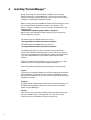
2.
Installing "Format Manager"
Some of you may not have installed TPS300_Tools already,
which includes the Format Manager. Some may not even have
installed Leica SurveyOffice (LSO) yet. All you need to know about
complete or additional installation follows.
Before running the LSO installation wizard, we recommend to close
all running windows applications. Place your CD-Rom TPS
Series, (Art.No. 713765) in your PCs CD slot and browse for the
following path:
OSW\Soffice\YOUR-Language\Disk1\; Setup.exe
Setup starts. The installation wizard will guide you through the
whole installation process.
The default path for WinNT platforms is set to:
D:\ProgramFiles\LeicaGeosystems\SurveyOffice.
The default path for Win98 platforms is set to:
C:\ProgramFiles\LeicaGeosystems\SurveyOffice.
The default path may vary, if any of LSO's components where
previously installed in a different path or drive. We recommend to
confirm our suggested path, because any further Leica Application
(e.g. TPS-CAD, Fieldlink, etc) would be installed at the same
location.
If LSO has already been installed on your PC or Laptop, you don't
need to perform a complete LSO package installation.
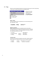
Choose the preferred SETUP type according your requirements:
Typical:
To perform a complete installation of LSO, including the necessary
Format Manager, please choose the Typical installation option.
We recommend this option if none of LSO's components have been
installed previously.
Compact:
Program will be installed with a minimum of required options, e.g
for Notebook installations. Be aware, that this option will NOT
install Format Manager.
Custom:
This option is recommended if LSO has been installed previously,
but not TPS300 Tools, including FM. You may also use the
Custom option for installation of other components.
4
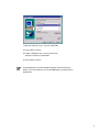
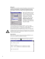
1. Window "SETUP Type": choose "CUSTOM
2. Press "NEXT" button
3. Enable "TPS300 Tools" in the components
selection window to install FM.
4. Press "NEXT" button
Format Manager must be installed together with Leica Survey
Office. It is not possible to run Format Manager as a stand-alone
application.
5
3.
Starting "Format Manager"
According to Microsoft Windows policy, applications are either
being started by clicking the corresponding *.exe file or creating
a shortcut icon on your desktop or in a specified folder. We
recommend to place the main LSO icon on your desktop.
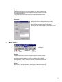
3.1 Starting Format Manager from the main application
To run the FM please follow the steps below:
1. Start Leica SurveyOffice
with the corresponding icon
on your desktop, or by
calling MAIN.exe in the
LSO folder.
2. Click the ellipse External
Tools
3. Choose the option
TPS300 Tools, and...
4. ...select Format Manager
3.2 Starting Format Manager as a stand-alone application
It is also possible to run FM as a stand-alone application. To create
and test Format Files successfully, you only need to run FM and
later the DXM for the file transfer and final testing.
Double click FM.exe
Browse for the corresponding file with your windows explorer or
other browser. Double click the file FM.exe which you may find
in the default directory.
D:\ProgramFiles\LeicaGeosystems\SurveyOffice\UserTools\FormatManager\FM.exe
Install a FM icon
Click the right mouse button, while beeing on the active windows
desktop and choose option NEW -> SHORTCUT. The
automatically evoked windows wizard will guide you through the
process. Browse again for the FM directory:
D:\ProgramFiles\LeicaGeosystems\SurveyOffice\UserTools\FormatManager\FM.exe
and choose FM.exe. Select or retype a name for your shortcut
icon. Windows will create a special icon to run Format Manager
as stand-alone application.
Once you have started FM it will take a couple of seconds until FM
is completely initialized and a Format File Type will appear.
6
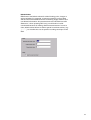
3.3
Format file type / Template
The LSO Format Manager basically provides three different types of
format file templates. One is dedicated to GPS500, which supports
GPS related format functionality, the others are designed to work
with TPS300/700.
· GPS500 (GPS500_Standard): The GPS500_Standard Format
File contains GPS specific headers and export strings. Be
aware that GPS format files will not work successfully on Total
Stations!
· TPS300/700 (Basic or Standard): The difference between Basic
and Standard is simply a difference of some single headers or
strings. The functionality of both is equal. The standard format
allows additional headers and strings for Orientation
Measurement (TPS), Station Residuals (TPS), as well as an
additional Default Exportstring. We recommend to use the
TPS300_Standard Format File type to meet any requirements.
Choose TPS300/700_Basic or _Standard to open a new Format File
or press CANCEL to abort. You will be able to open or create
different files without closing the active sheet.
Use the icons in the menu bar, to open, save, and create new or
existing titles.
7
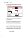
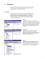
4.
Format Manager Layout
Each Format File will be displayed in a separate Window. A Format
Window consists of a caption, a Tree View, an Edit View and a
Format String Preview.
Caption
Edit View
Tree View
Format String
Preview
Caption
The Format name (e.g. REPORT1.FRT) is displayed as the Format
Window caption. The template name (e.g. TPS300_standard) is
displayed in the status bar.
Tree View
All Format String categories, Datablock types and Format Strings of
the active Format File are listed in the Tree View . This allows an
easy access to all headers and export format strings within a
Format File. Tree View items can easily be extended by clicking the
+ or double-clicking the corresponding item.
Edit View
A Format String will be displayed in the Edit View once it has been
selected in the Tree View. The Edit View works similarly to any text
editor. An additional dialog appears that enables you to insert and
edit export variables. Similar to an editor, additional text may be
entered or edited using the keyboard. The number of characters
allowed is defined in the Format Template. In the Edit View some
characters have a special meaning:
« »
¬
·
8
Variable delimiters
Tabulator (= 8 spaces)
space
5.
Format File
Each Format File consists of headers and strings. This chapter will
inform you about the possibilities and limitations of both, while
formatting options will be discussed later.
5.1
Header
The Header section in the Tree View contains three different types
of headers ("General", "Applications" and "Blocks"). Expanding the
header section is either possible by clicking the + or doubleclicking on "Header". To view or edit a header, highlight it with a
mouse click and type in the contents in the office view. A header
can only contain static text.
General
The general header section contains a File
Header and a File Footer. The File Header will be
placed at the very beginning of every instrument
data output. The File Footer will be placed at the
very end of every instrument data output. Both
header and footer will be printed only once in
each file.
Applications
Application Headers separate Data Blocks
registered within different applications.
Whenever an application is started the specified
application header text will be printed at the
beginning of this application.
Blocks
Block Headers (e.g. Code-Header) are placed at
the beginning of a new Data Block. A block
specifies a unique type of data (e.g. Code,
Results) which can be recorded at any occasion
within applications or system measuring.
9
5.2 Export Formatstring
Data Block
A Data Block is a data record generated by an onboard instrument
application. The output data depends basically on the Data Block
type. The number of available Data Blocks and their names (for
example Measurement, Orientation) are defined by a Format
Template, which varies for different series of instruments.
Export String
An export string is basically a sequence of variables. A variable
represents a specific data item within the instrument (e.g. Hzangels, Code ID, etc). The maximum number of variables per string
depends on the used template. All TPS templates are at the time
limited to 30 variables.
A Format String may contain text and variables. At least one
application must be assigned to every defined Exportstring. It will
be used to generate all data output by the assigned application.
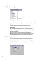
5.3 Default Export String
The purpose of designing a default string is to assign a default
format to any variable which was not individually formatted. Any
newly inserted variable will be formatted according to the default
settings, if no individual changes were made. However, the settings
of a variable can be edited at any time.
The default format window is accessible from the menu bar:
Options -> Defaults
10
6.
Formatting a String
Double click any variable in the EDIT view to get to the
Formatting window.
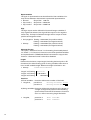
6.1
Settings
Alignment
The alignment defines the string orientation within a defined string
length.
Example: LEFT/RIGHT alignment
· Alignment RIGHT
Angle Hz: 321.1111
· Alignment LEFT
Angle Hz: 321.1111
11
Representation
The type of representation can be defined for float variables. You
may choose between decimal and exponential representation.
· Normal
· Exp. basis e
· Exp. basis E
Slope Dist: 609.173
Slope Dist: 6.092e+02
Slope Dist: 6.092E+02
Sign
The sign output can be defined for float and integer variables. If
only negative is selected, the sign will be output out for negative
values only. If always is selected the sign will be output for both
positive and negative values.
· Only negative Easting: 140123.877 (for positive values)
Easting: -140123.877 (for negative values)
· Always
Easting: +140123.877 (for positive values)
Easting: -140123.877 (for negative values)
Alternate Format
The option Alternate Format is a formatting functionality based
on PrintF (C+function). However none of the specified variables
are implemented in TPS300/700 Series instruments to support this
function. Alternate Format is therefore disabled.
Length
Defines the minimum output lenght (including decimal point or fill
characters) for either floating point or string variables. Note that "0"
is an invalid variable length. Maximum lenght is limited to "20".
· Always
12345678901234567890
Length 10 Easting: 140123.877
Length 15 Easting:
140123.877
Length 20 Easting:
140123.877
Precision
a) Float variables: Precision defines the number of decimals
· Length 15,
precision 5
precision 3
Easting:000140123.87700
Easting:00000140123.877
b) String variables: Precision defines the maximum string length. If
"Length" is larger than precision the remaining
space will be used with fill characters. Precision
set to "0" will not set string length limitation.
· Length 8,
12
precision 3
precision 0
PtNr: 00000PFL
PtNr: 00PFL100
Fill Character
Fill characters are used to extend strings with fewer characters than
its length is defined as. Either "spaces" or "0" can be selected as fill
characters.
· fill character 0
· fill character _
Easting:0000000000140123.877
Easting:
140123.877
Unit
Referencing specific units to certain variables will output the
corresponding values in the specified unit no matter which unit is
set on the instrument.
· Unit meter
· Unit US Feet
· Unit Intl. Feet
Easting : 122001905.579 [m]
Easting : 400268719.700 [us ft]
Easting : 400267918.555 [Intl.ft]
· Unit gon
Hz-angle: 371.7449 [gon]
· Unit decree decimal Hz-angle: 334° 34' 13" [deg.sexa]
· degree sexag.
Hz-angle: 334.5704 [deg.dec.]
Hz-angle: 5947.9190 [mils]
Hz-angle: 5.8394 [rad]
Enabling the "use system unit" button, will
read instrument unit settings regardless of FM unit settings. Be
aware, that sexagesimal output requires special formatting.
Creating a format in GON-style for example, but reading
instrument units "sexagesimal" will output the correct digits, but in
an unusable format.
13
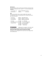
6.2 Flags
Flags are special attributes assigned to strings and floating point values. Depending
on the type of variable, FM offers the following options:
Double click on the
variable in the EDIT
view to get the
Formatting options
for export variable.
Allow scaling:
Floating variables will be multiplied by the entered scalling factor.
E.g. scale factor "1000"
· flag enabled
· flag disabled
Easting:
Easting:
140123877.000
140123.877
Suppress rounding:
When "suppress rounding" is enabled, the true value will be
truncated (instead of rounded) at the specified precision. Disabling
the "suppress rounding" will mathematically round the true value
to its specified precision (e.g. ".58").
· true value
· suppress rounding
· rounding
Easting:
Easting:
122001905.579
122001905.57
122001905.58
Truncate value:
Variable values will be truncated from the left to reach the defined
string length. Our example shows a string truncated at 9 digits.
· disabled
· enabled
14
Easting:
Easting:
122001905.579 ("no truncate")
01905.579 ("truncate")
7
Menu Bar
There are basically only two menu options specificly related to FM:
"Format" and "Options". All other topics are global windows
functions and will not be explained.
7.1
Menu Format
·
·
·
·
Assign Application
String Pool (Load/Save)
Export Preview
Properties
Assign application
Assigning applications limits the output to data recorded in specific
applications. Various applications can be assigned to each format
string. At least, one application has to be assigned. Data measured
in non-assigned applications will be output in the default
exportstring format. Therefore, it is not possible to assign
applications to a "DEFAULT" exportstring.
Example:
In the example above, only the onboard application "Area" was
assigned to the exportstring of datablock type "Measurement TPS".
Any measurement recorded within the area application would be
output with the specific "Exportstring " format. Any other data
measured with the TPS300/700 would only be output, if a Default
exportstring is defined.
15
String pool
The String Pool works like a format string library. Any format string
created can be saved to the String Pool. All strings in the string
pool can be used globally, i.e. in different format files, than they
were created in. There is no relation to the original Format file at
all.
Select the Data Block Type and
Export String in the Tree View.
To save an existing string to the
string pool, click the right
mouse button to evoke the
String Pool menu. Enter an
individual string name. The
string pool wizard will also
record the format template and
the datablock type in which the
string was created.
To load a string from the string pool library, press your right
mouse button and perform "String pool --> Load". Since the string
pool is a global provider, you may use the selectionfilter to
preselect the template and datablock type to find your string faster.
Loading a string from the string pool will replace the current string.
Therefore ensure that you really want to delete the current string, or
that the exportstring is empty.
Export preview
Once, you have created an output format string, FM allows you to
preview the complete string with dummy data.
A separate preview window will appear and show you each string
tree time in sequence. Press
16
to perform an export preview.
Note:
The Export Preview will not be updated if you make changes in the
Format File.Therefore, you must perform a new preview to view the
modified Format File.
To print an Export Preview, the Export Preview window must be
active.
Properties
All common windows applications provide a
special properties window to specify author
and other file specific information. Filling in
properties will make it easier to administer or find
formats.
7.2
Menu Option
· Format
· Defaults
Format
The Settings for the currently opened Format File can be defined.
When a new Format File is created the default Format Settings will
be assigned automatically. To view or modify the Format File
settings select "Format" from the Options menu and then select the
property page you want to view or modify.
Scales
Scale factors can be defined for all unit types. FM will multiply all
float variables with its specific scale factor before outputting them.
17
Example:
Hz-Angle
Slope Dist
Temperatur
Pressure
:
:
:
:
Hz-Angle
Slope Dist
Temperatur
Pressure
:
321.1111
:609173.000
:
12.000
:
0.076
Linear scaling may be used to convert data from [meter] to
[millimeter] or to convert pressure from [mBar] to [Bar]
Units
Any combination of angular, linear, temperature
and pressure units can be selected. FM will
convert the measured values into the selected
units, regardless of the einstrument settings.
Type
Units
Angular units
Radians, Gons, degrees (sexagesimal),
degrees (decimal), mils
meter, Intl. feet, US feet
Degrees celsius, Kelvin, Fahrenheit
mm, mmHG, InchHG, Hectopascal
Linear units
Temperature units
Pressure units
18
321.1111
609.173
12.000
760.000
Default Values
FM allows to set Default values for either floating-point, integer or
string variables. For example, a customer needs to protocol data
with a customized fieldbook format containing angle, distance and
coordinate information. Any measurement recorded without valid
distances (...when pressing REC only), would lead to invalid
coordinates because of missing distance measurement. In such a
case, default values allows to define special coordinate values, (e.g.
- - - - - ) to visualize the use of specific recording technique in the
field.
19
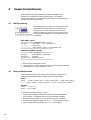
8.
Sample Format Elements
Formats often consist of standardized elements. Rather than
explaining a complex format at the beginning. This chapter
focusses focussing on sample elements, which can play a key part
in any particular output format.
8.1 Job Exportstring
At the beginning of a job, it can be useful to have
a general information header, considering job
and operators name, or the instrument used.
Since this data may vary from job to job, we use
corresponding variables to record data from the
instrument.
EDIT VIEW: "INPUT"
==========JOB·INFORMATION==========
Project···:·«Jobname»·(«Job Comment 1»)
Operator··:·«Operator»
Instr/S.No:·«Instrument·type»/«Instrument·No»
===================================
FORMAT PREVIEW: "OUTPUT"
==========JOB INFORMATION==========
Project
: BLDG_EAST01 (FACTORY)
Operator : JohnDoe
Instr/S.No: TCR305/640054
===================================
· All text strings, Alignment: LEFT
· Length set to "1"; Every string will take as much space as needed
· Limit length of <<instrument No>> to "6"
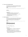
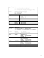
8.2 Time and date function
Time and date functions are often used to identify a sequence of
measurements. FM provides full date and time functionality.
INPUT:
Time:···«Time·(hours-24)»:«Time·(Minutes)»:«Time·(Seconds)»
Date:·«Date (day)»/«Date (month)»/«Date (long year 1998)»
OUTPUT:
Time:
17:13:17
Date: 2/07/1998
· Create information text (eg. "Time:").
· Insert time and data variables as requested. Browse datablock
type "Station" or "Measurement" for time and data variables.
· Change variable length to "2", except for long year variables.
· Additionally enable fill character "0" or "_" for single digit values.
· Type in separation characters (e.g. "/" or ":") manually.
20
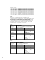
8.3
How to create sexagesimal angles
Sexagesimal angles require a special format handling. Instead of a
single variable (e.g. for gons) FM supports 3 different sexagesimal
variables for degrees, minutes and seconds.
INPUT
Hz:«Horizontal angle (Deg)»°«Horizontal angle (Min)»«Horizontal angle (Sec)»
V:·«Vertical angle (Deg)»°«Vertical angle (Min)»«Vertical angle (Sec)»
OUTPUT
Hz: 321°1111"
V: 88°1212"
FORMATTING:
· Insert sexagesimal "degrees", "minutes" and "seconds"
variables from the data block type "Measurement".
· Set the length to "3" for sexagesimal degrees, "2" for minutes
and seconds. Select spaces as fill characters.
· Set alignment to "right".
· Insert sexagesimal unit symbols manually (e.g. °,',").
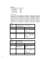
8.4
Data in sequence
FM allows you to create an endless number of ASCII formats. One of
the most common formats is the sign delimited data in sequence
format. Sign delimited Format Files can easely be imported into
almost any windows application (e.g. EXCEL, WORD, etc.).
INPUT:
«Point·ID·(Target)»;·«Horizontal·angle»;·«Vertical·angle»;·«Slope·distance»
OUTPUT:
PtNr.
HZ
V
SD
DFB03; 41.7433; 94.7544; 3.151
DFB04; 60.8726; 71.8583; 4.030
DFB05; 37.4635; 341.3971; 2.706
AA.1; 51.0244; 69.8460; 2.535
0; 51.0248; 69.8462; 2.533
1; 51.0243; 69.8461; 2.533
AB.1; 51.0244; 69.8464; 2.534
FST1; 5.7986; 80.8330; 3.242
FORMATTING:
· Set variable length to 1, so that every value takes as much
space as it really needs. As a separator, you may insert a
; manually.
· Set the precision of angle units to 4 or as you like.
· Set the precision of distance units to 3 or as you like it.
· When you download data in the above format, the Excel import
with import wizard will easely recognize your delimiter and put
measured values in separte cells.
21
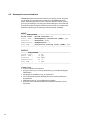
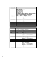
8.5 Atmospheric correction block
TPS300/700 instruments have a built-in correction record. Any time
you change your atmospheric constants or the EDM measuring
mode, the firmware will record a correction block to inform you of
your current settings. You may print those settings in a Format File
to recall the meteorological conditions at the time you measured in
the field. Following is an example of these special variables.
INPUT:
------ATMOSPHERE---------------------------------Prism·const:·«Prism·constant»·mm
Atmos.·PPM·:·«Atmospheric·correction·(PPM)»·ppm
Pressure···:·«Pressure»·mmHG
Temperature:·«Temperature»·°F
Proj.PPM···:·«Projection·scaling·total·(PPM)»·ppm
-------------------------------------------------OUTPUT:
-------ATMOSPHERE--------------------------------Prism const:
0 mm
Atmos. PPM :
30 ppm
Pressure
:
760 mmHG
Temperature:
62 °F
Proj.PPM
:
0 ppm
-------------------------------------------------FORMATTING:
· create a header environment
· change units to your local preferences (e.g. mmHG and degree
Fahrenheit)
· set length of variables to e.g. 8, precision 0
· you may define separate scaling factors for either pressure or
temperature
· PPM values are fix, no modifications possible
· type the units manually behind the variable inserted to avoid
confusion.
22
9.
Errors
Format Error
Format Error might occur when editing or loading a Format String
from the String Pool. The message appears when the Format string
is saved to the Format File after selecting a different Format String.
Correct the Format String either by changing the length or
removing variables.
Dialog Data Validation Error
A Dialog Data Validation Error occurs when the field entry is not
valid and OK is selected. The expected range will be displayed.
Modify the field input so that it is included in the input range.
Format Template Error
A Format Template Error occurs when the Format Template File is
corrupted. Reinstall the Format Manager from the installation
media. If the Error still occurs contact Leica for support.
Profile Error
A Profile Error occurs when the profile file is corrupted. Reinstall
the Format Manager from the installation media. If the Error still
occurs contact Leica for support.
Invalid Format File Error
An Invalid Format File Error occurs when for some reason the
Format file is corrupt. Delete the corrupted Format file and create a
new Format File with the same contents.
23
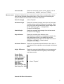
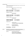
10. Implemented Export Variables
This section basically presents a reference list. All available
variables are listed with a short explanation of their functionality.
Many of the variables exist in more than one datablock type and
will therefore be explained only once.
___________________________________________________________________________________
Code
For detailled coding information, please refer to the
corresponding user manual.
Attribute Name
Attribute
CodeID
Alphanumeric value with a
maximum length of 8 characters
(e.g. CodeID: TREE).
Code description
Additional information line for up to 30
characters. Availability of code
description on the instrument depends
on layout version. LSO fully supports the
code description functionality.
Attributes
Up to 8 attributes allowed. Attributes are
additional information text, limited to 16
characters per line.
(e.g. Info1: CONCRETE_PYLON)
Attribute names
Attribute names define a group of
attributes. The length of attribute names
is basically limited by the corresponding
TPS layout. However, LSO supports
a maximum of 10 characters.
(e.g. "Info1:" is an attribute name)
_______________________________________________________________________________
Corrections
Correction blocks are recorded to the internal memory any time
the EDM settings have changed.
Prism constant
24
· onboard recording range [0..±999mm]
· variable output in [m]; e.g. 0.035 for prism
constant = 35mm
· set scale factor to 1000 to get mm
· set precision to 3, to show all decimals
Atmospheric correction (PPM)
· calculated PPM value from atmosperic
data dialoge
· Precision fixed
· Scaling NOT possible
· e.g. output -23 [ppm]
Pressure
· calculated air pressure from atmospheric
data dialogue
· Instrument supports integer values only
(e.g. 1013 [mbar])
· separate scaling possible (option pressure
scale)
Temperature
· manually entered temperature in atmospheric
data dialogue
· Instrument supports integer values only
(e.g. 12 [°C])
· separate scaling possible (option temperature
scale)
Projection Height
Offset central meridian
Projection scaling total (PPM)
Projection scaling (PPM)
Height reduction (PPM)
Relative humidity
Refraction coefficient
on request
on request
· refer to the manual for further information
· fixed instrument value 0.130
Elevation above mean sea level
· e.g. output 605.500 [m]
· scaling possible, using option Linear Scale
Scale factor central meridian
· fixed output 1
· scaling possibe, using option Linear Scale
EDM type
· fixed text value
RL: Reflectorless
IR: Infrared
25
Prism Type
· fixed text value
User
Round
(GPR1,
mm=0)
Mini
(GMP101, mm=+17,5)
360°
(GMP74, mm=+23,1)
EDM measure mode · fixed text value
RL_Short; (Red Laser, reflectorless)
RL_Prism; (Red Laser, Prism mode)
RL_Track; (Red Laser, Reflectorless tracking)
IR_Fine; (Infrared, prism mode, high accuracy)
IR_Fas; (Infrared, prism mode)
IR_Track; (Infrared, prism mode tracking)
______________________________________________________________________________________________
Fixpoint
Variables of the datablock type Fixpoint will read manually entered coordinates or
data retrieved from the onboard fixpoint. Data memory without valid coordinates
will be printed with DEFAULT values.
Point ID (Target)
Target (East)
Target (North)
Target (Elevation)
Point description
Point class
Target point number (e.g. 11001)
Easting coordinate of measured point (e.g. 5401.220)
Northing coordinate of measured point (e.g. 3701.951)
Elevation of measured point (e.g. 654.000)
Point description assigned to target PointID
GPS only
Job Comment 1 / 2
Additional text lines for up to 16 alphanumeric characters,
each. Job comments can only be entered onboard the
instrument and are not allowed to edit.
______________________________________________________________________________________________
Job
Time
26
Time variables read the actual clock time from the
instrument's system.
Time (Seconds): 1..60
Time (Minutes): 1..60
Time (hours-24): 1..24
Date
Date variables read the actual date form the instrument's
sytem.
Date (day):
1..31
Date (month):
1..12
Date (short year 99): 0..99
Date (long year 1999): 0..9999
Jobname
Reads the jobname of the active job.
Operator
Reads the operator (OPER:) value of the active job at
the time the corresponding string has been recorded.
Instrument Type
Reads the instrument type from the system. This is
a fixed value, depending the type of instrument you
are using (e.g. TCR305).
Instrument No
Reads the instruments serial number, which is also a
fixed value (e.g. 640054, which is a TCR305).
______________________________________________________________________________________________
Measurement Variables of datablock type measurement read out the corresponding values
from the last recorded measurement block. For any block not containing the
request variables, the format will read the last valid values.
Point ID (Target)
refer to "Fixpoint"
Horizontal Angle
Reads the recorded Hz angle value from the instrument.
Variables allows unlimited scaling and formatting. Make
sure your output string matches the specific angle units
format options (e.g. gon --> sexagesimal).
Example: 243.5891 [gon]
Vertical Angle
Reads the recorded vertical angle from the instrument.
Example: 101.4763 [gon]
Slope distance
Reads the recorded slope distance value.
If the distance is invalid (e.g. only angles recorded in the
last measurement block), the variable will read the
specified default value, which can be edited in the menu:
OPTION -> FORMAT -> Default values.
Example: 1522.143 [m]
Horizontal Distance
Reads the computed horizontal distance value, which is
calculated with the originally measured angle and distance
value.
Height Difference
Reads the computed height difference to the target point,
which is calculated with the originally measured angle
and distance value.
Target (East)
Target (North)
Target (Elevation)
Time (Seconds)
Time (Minutes)
Time (hours-24)
Date (day)
Date (month)
Date (short year 99)
Date (long year 1999)
refer to "Fixpoint"
General GSI Block information
27
For detailed Leica GSI format information, please refer to
our document WILD ONLINE GUIDE
(Art.No GZ-366 0en).
GSI Block information
Example: 21.012+124 04510
Pos 1-2: Word index (e.g. "21" for Hz Angle
Pos 3-6: Block number (GSI), for WI11 blocks
Pos 4:
Compensator flag
Pos 5:
GSI flag
Pos 6:
Unit flag
Pos 7:
Sign
Pos8-15: Data
Pos 16:
blank (separating character)
Blocknumber (GSI)
Incrementing block number (used in GSI output) to count
measurement and coding records. Block No. 1 signalizes
the first block.
· single digit, integer value
Counter (Cnt++)
Any recorded block gets a continuously incremented
number, no matter wether a new job was created or not.
V-Index (GSI)
· vertical index operation flag
· single digit, integer value
· pos 5
Hz Correction (GSI)
· Hz correction operation flag
· single digit, integer value
· pos 5
Inputmode (GSI)
· GSI input mode flag
· single digit, integer value
· pos 5
(e.g. "0" = measured value)
Units (GSI)
· GSI unit flag
· single digit, integer value
· pos 6
(e.g. "2" = gon)
Horizontal Angle (Deg.)
· integer value
· range [0..359]
(e.g. "153" degree)
Horizontal angle (Min)
· integer value
· range [0..59]
(e.g. "45" minutes)
28
Horizontal angle (Sec)
· integer value
· range [0..59]
(e.g. "13" seconds)
Vertical angle (Deg.) refer to Horizontal angle (Deg.)
Vertical angle (Min) refer to Horizontal angle (Min)
Vertical angle (Sec) refer to Horizontal angle (Sec)
Hz count direction
· Text value
Left (counter-clockwise)
Right (clockwise)
Reflector Height
· floating point value
· full scaling and formatting options available
(e.g. 1.300 [m])
______________________________________________________________________________________________
Orientation Measurement
Reflector height
refer to "Measurement"
______________________________________________________________________________________________
Orientation Residuals
If more than one target is measured in orientation applications, point residuals will
be calculated, according the least square method.
Point-ID (Residual)
· Target PointID, for which residual is calculated for
· alphanumeric value
· refer to PointID
Residual (Dist)
· floating point value
· difference of measured and calculated distance
to target point
Residual (Height Diff)
· floating point value
· difference of measured and calculated height
difference of target point
Residual (Hz)
· angle value
· difference of measured and calculated Hz angle
to target point
Residual (Hz-Deg)
Residual (Hz-Min)
Residual (Hz-Sec)
refer to Hz-angle (Deg)
refer to Hz-angle (Min)
refer to Hz-angle (Sec)
29
______________________________________________________________________________________________
Orientation Result
Orientation results are mathematically calculated values, as a result of the multiple
target orientation application.
StdDev (Ori-correction)
· standard deviation of calculated orientation
angle
· floating point value
StdDev (Ori-correction-Deg)
StdDev (Ori-correction-Min)
StdDev (Ori-correction-Sec)
refer to Hz-angle (Deg)
refer to Hz-angle (Min)
refer to Hz-angle (Sec)
Orientation correction
· floating point value
· refer to Hz-angle
Orientation correction (Deg)
Orientation correction (Min)
Orientation correction (Sec)
Orientation Hz-Angle
· floating point value
· refer to Hz-angle
Orientation Hz-Angle (Deg)
Orientation Hz-Angle (Min)
Orientation Hz-Angle (Sec)
Orientation Face
refer to Hz-angle (Deg)
refer to Hz-angle (Min)
refer to Hz-angle (Sec)
refer to Hz-angle (Deg)
refer to Hz-angle (Min)
refer to Hz-angle (Sec)
· floating point value
I (Face Left; Hz fine drive on the right hand side)
II (Face Right; Hz fine drive on the left hand side)
Point count
· incrementing integer value
· counts no. of orientation
target points (max. 5 allowed)
Ori Pt ID (Result)
Point ID (Residual)
refer to Point ID
refer to Point ID
______________________________________________________________________________________________
Results
Result variables are calculated values from specific onboard functions or
applications (e.g. AREA). Results in a measurement will for example always read
the last valid values form the previously recorded result block.
StdDev (..)
30
· floating point coordinate values
· applied in FREE STATION application
· represents position error of station point
· applied formula: Ö(s.Dev E)2+(s.Dev N)2
Area
· floating point value
· fixed units
· applied in AREA application
e.g. 4756.490 [m2]
Circumference
· floating point value
· fixed units
· applied in AREA application
e.g. 214.644 [m]
Point count
· integer value [1...n]
· applied in AREA application
· counts No. of recorded points for area calculation
Result height difference
· floating point variable (e.g. 15.721 [m])
· applied in TIE DISTANCE application
· Height difference between measured Point1
and Point 2
Result Point ID1/2
· string value (e.g. Pt102)
· applied in TIE DISTANCE application
· PointID of measured points 1/2
Stakeout difference
/East
/North
/Elev
· floating point variables (e.g. 12.442 [m])
· applied in SETTING OUT application
· difference of measured and calculated Stakeout
Coordinates and Elevation (dE, dN, dH)
Result slope distance
· floating point variables (e.g. 412.810 [m])
· applied in TIE DISTANCE application
· slope distance of point-to-point line from "P1" to "P2"
of "TIE DISTANCE"
Result horizontal distance
· floating point variables (e.g. 372.527 [m])
· applied in TIE DISTANCE application
· Horizontal (=plan) distance of point-to-point line from
P1 to P2 of TIE DISTANCE
Computed bearing
· floating point angle value (e.g. 12,4712 [gon])
· applied in TIE DISTANCE application
· calculated bearing from Point1 to Point2 in "TIE
DISTANCE"
Computed bearing
/Deg, /Min, /Sec
· refer to computed bearing
· refer to Datablock MEASUREMENT
31
Station
Station variables, used in strings other than Station, will print the last valid
recorded value. E.g. if Station variables are being used in the datablock type
Measurement, the system will return the last valid station data, recorded in the
memory. If no valid station is set (e.g. after reinitializing mem), the specified
default value will be printed.
______________________________________________________________________________________________
Target Point
Manually entered coordinates or fixpoints recorded in memory, used as target
points for applications (e.g. SET ORIENTATION, STAKEOUT, or FREE
STATON).
For further information, please refer to Datablock Type MEASUREMENT.
32
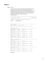
Annex 1
Report format
Report formats are often used as measurement and data protocols
or documents. The purpose is to visualize recorded data in a
readable format. As a first exercise, this example guides you trough
the necessary steps of creating a report format. This Format File
consists of a combination of headers and output-strings and
will therefore cover a lot of FMs functionality.
Example data file:
==================================================
SurveyOffice FM V1.1
Report.FRT
==================================================
Jobname: BLDG4_WST (Operator: MM-3519)
Instr. : TCR305/640054
Date
: 11/15/1999
NEW STATION--------------------------------------StID:ST-105
hi: 1.500
East: 771.200 North: 535.500 Elev: 13.250
MEASURE&RECORD-----------------------------------PtID:2201
hr
:
1.60
East: 778.216 North: 539.819 Elev: 11.942
PtID:2202
hr
:
1.60
East: 778.251 North: 540.392 Elev: 12.987
PtID:2203
hr
:
1.60
East: 775.949 North: 537.817 Elev: 13.611
PtID:2204
hr
:
1.60
East: 776.179 North: 536.440 Elev: 13.920
PtID:2205
hr
:
1.60
East: 776.225 North: 536.270 Elev: 14.159
REMOTE ELEVATION---------------------------------PtID:2210
hr
:
1.20
East: 769.776 North: 538.583 Elev: 13.453
PtID:2210B
hr
:
0.00
East: 769.776 North: 538.583 Elev: 16.456
PtID:2210C
hr
:
0.00
East: 769.795 North: 538.591 Elev: 17.226
MEASURE&RECORD-----------------------------------PtID:2300
hr
:
1.70
East: 772.581 North: 539.017 Elev: 14.150
PtID:2301
hr
:
1.70
East: 774.000 North: 539.099 Elev: 13.243
End of file.
33
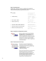
Step1 Format Structure
Use the menu Options->Format to prepare units, scales and
default values according your requirements. Think about the needs
of your format and plan a suitable format structure:
e.g
· File header
===============
SurveyOffice ...
=================
·
Job Exportstring
Jobname: BLDG4...
Instr. : TCR305/...
Date
: 11/1...
·
Block header Station
NEW STATION---
·
Station export string
StID:ST-105...
East: 771.20 Nor...
·
Application header Measure&Record
MEASURE&RECORD---
·
Application header Remote Elevation
REMOTE ELEVATION---
·
Measurement(TPS) export string
PtID:2210...
East: 769.776 No...
Step2 Create
Create BlockBlock- and
and Application
Applicationheaders
headers
Open the header section by pressing the
corresponding + signs in the tree view.
Highlight the general File Header to
create a simple header element in the edit
view. Any ASCII sign is accepted. However
headers do no support export variables.
The same procedure is valid for application
and block headers.
Step3 Create export format strings
Click the tree view and highlight the
required formatstring. In this example,
three different export strings will be used.
- Job Exportstring
- Measurement Exportstring
- Station Exportstring
Varying from exportstring to exportstring, a
separate window with corresponding
insert variables will appear. However you
are allowed to browse for variables of
different datablock types at any time. Insert
the variables and additional text as
required (e.g. Job, Operater, etc.)!
34
Export String:
Edit View:
Job
Jobname:·«Jobname»·(Operator:·«Operator»)
Instr.·:·«Instrument·type»/«Instrument·No»
Date···:·«Date·(month)»/«Date·(day)»/«Date·(long·year·1998)»
Preview:
Jobname: xxxxxx (Operator: yyyyyy)
Instr. : zzzzzz/nnnnnn
Date : mm/dd/yyyy
String Element:
xxxxxx
Variable
Jobname
yyyyyy
zzzzzz
nnnnnn
Operator
Instr.Type
Ser.No.
mm
dd
yyyy
Date month
Date day
Date year
Export String:
Edit View:
Measurement
PtID:«Point·ID·(Target)»·hr···:·«Reflector·height»
East:«Target·(East)»·North:«Target·(North)»·Elev:«Target·(Elev)»
Preview:
PtID:nnnn
East: xxx.xxx
hr : mm.mm
North: yyy.yyy Elev: zzz.zzz
String Element:
nnnn
Variable
PointID
mm.mm
hr
xxx.xxx
Target East
yyy.yyy
zzz.zzz
Target North
Target Elev
Formatting
Alignment: left
Length:
8 (or as required)
Precision:
0
Alignment: right
Sign: only negative
Length:
6 (or as required)
Precision:
2 (or as required)
Alignment: right
Sign: only negative
Length:
8 (or as required)
Precision:
3 (or as required)
refer to Target East
refer to Target East
Formatting
Alignment: left
Length:
1
Precision:
0
refer to Jobname
refer to Jobname
Length:
6
Precision:
0
refer to chpt.9.2
refer to chpt.9.2
refer to chpt.9.2
35
Export String:
Edit View:
Station
StID:«Point·ID·(Station)»···hi:«Instrument·height»
East:«Station(East)»·North:«Station(North)»·Elev:«Station(Elev)»
Preview:
StID:nnnn hi : mm.mm
East: xxx.xxx North: yyy.yyy Elev: zzz.zzz
String Element:
nnnn
mm.mm
xxx.xxx
yyy.yyy
zzz.zzz
Variable
StationID
hi
Station East
Station North
Station Elev
Formatting
refer to PointID
refer to PointID
refer to Target East
refer to Target North
refer to Target Elevation
Step3 Application assignment
Before saving a Standard template Format File, at least one
application has to be assigned to an Exportstring1,2,
. Please
refer to chapter 7 for detailed information. You will not need to
perform application assignments, when using Default
exportstrings.
Step4 Format preview
Once having completed a Format File, we recommend to perform a
format preview. The preview function will print an example of each
defined export string three times without loading the format to the
instrument. Finally satisfied with the output data you can load the
file to an instrument and make a real life test. Go and collect any
data in your office or in the field and check what your file creates.
Improve any of the above steps until the Format File is doing
exactly, what your aim was at the beginning.
36
Annex 2
GSI Format
GSI output formats consist of basically any sequence of measured
values lead by a specific word index (WI). The example below, is a
typical standard mask output containing pointnumber (WI11),
horizontal angel (WI21), vertical angle (WI22), slope distance (WI31),
combined PPM and prism constant values (WI51), reflector height
(WI87) and instrument height (WI88). For further information on GSI
formatting options, please refer to the Wild ONLINE guide.
Example GSI data file:
110001+0OP-1340 21.002+29459500 22.002+10576550 31...0+00041307 51
87
88
110002+0OP-1341 21.002+29375900 22.002+10522500 31...0+00032847 51
etc
110003+0OP-1342 21.002+29341150 22.002+10451100 31...0+00029673 51
etc
110004+0OP-1343 21.002+29147250 22.002+10321850 31...0+00020025 51
etc
110005+0OP-1344 21.002+28991450 22.002+10201550 31...0+00015033 51
etc
110006+0OP-1345 21.002+28679850 22.002+10068700 31...0+00010586 51
etc
Additionally to above data blocks, it is possible to output codes
and up to 8 code informations in the standard GSI format.
410018+000LYR15 42....+00A_OP12 43....+00000000 44....+000000G4 45....+00000000
410025+000LYR18 42....+00A_OP12 43....+00000000 44....+00000000 45....+00000000
One may create any kind of GSI formats to meet local requirements
(e.g Fieldprotocols, Postprocessing, etc). We recommend to use
always the Standard template for either TPS300 or TPS700 Format
Files. Since GSI does not have decimal delimiters, you need to
adjust scales as follows:
·
Menu Options-> Format -> Scales setting:
·
·
Menu "Options"-> Format -> Unit setting: as required
Menu "Options"-> Format -> Default value setting:
suggest to set values to "0"
EXAMPLE 1:
Customized GSI format (FM_GSI1.FRT)
·
Pointnumber
WI11
(Point ID)
·
Easting coordinate
WI81
(Target point easting)
·
Northing coordinate WI82
(Target point northing)
·
Code
WI41
(Code ID)
37
Example data file:
11001+0OP-1341 81...0+01982820 82...0+00839396 410002+000LYR12
11002+0OP-1342 81...0+01985960 82...0+00839542 410003+000LYR12
11003+0OP-1343 81...0+01995580 82...0+00839929 410004+000LYR12
11004+0OP-1344 81...0+02000563 82...0+00840229 410005+000LYR12
11005+0OP-1371 81...0+02014448 82...0+00842927 410013+000LYR14
11006+0OP-1372 81...0+02008086 82...0+00842610 410014+000LYR14
11007+0OP-1373 81...0+02004931 82...0+00842475 410015+000LYR14
11008+0OP-1380 81...0+02001744 82...0+00842324 410016+000LYR15
Step1
Open a new format file and browse for datablock type
Measurement(TPS) in the tree view. Use the Exportstring1 to limit
the data ouput to specific applications or use the Default
Exportstring to output all recorded measurement (see also KpXX
assign applications). For purpose of easier understanding, we
will explain each word index element separately, although all
indices would be in sequence in the edit view.
Step2
Element name: Point number
Edit View:
11 «Blocknumber (GSI)»+«Point ID (Target)»
Preview:
11xxxx+ nnnnnnnn
String Element: Variable
Formatting
"11"
Manual entry
---"xxxx"
Blocknumber
Alignment:
right
Sign:
only
negative
Length:
4
Fill character: 0
"+"
Manual entry
---nnnnnnnn
PointID
Alignment:
right
Sign:
only
negative
Length:
8
Precision:
0
Step3
Element name:
Edit View:
Preview:
String Element:
"81..."
"x"
+ nnnnnnnn
38
Easting coordinate
81...«Units (GSI)»«Target (East)»
81...x+ nnnnnnnn
Variable
Formatting
Manual entry
---Units (GSI)
Alignment:
Length:
Target (East)
Alignment:
Sign:
Length:
Precision:
Fill character:
right
1
right
always
9
0
0
Step4
Element name: Northing coordinate
Edit View:
82...«Units (GSI)»«Target (North)»
Preview:
82...x+ nnnnnnnn
String Element: Variable
Formatting
"82..."
Manual entry
---"x"
Units (GSI)
Alignment:
Length:
+ nnnnnnnn
Target (North)
Alignment:
Sign:
Length:
Precision:
Fill character:
right
1
right
always
9
0
0
Step5
Element name: Code
Edit View:
41«Blocknumber (GSI)»+«Code ID»
Preview:
41xxxx+nnnnnnnn
String Element: Variable
Formatting
"41"
Manual entry
---"xxxx"
Units (GSI)
Alignment:
right
Length:
1
+nnnnnnnn
Code ID
Alignment:
right
Sign:
only negative
Length:
9
Precision:
0
Fill character: 0
39
EXAMPLE 2:
Customized GSI format (FM_GSI2.FRT)
·
Pointnumber
WI11
·
Horizontal-Angle
WI21
·
Vertical-Angle
WI22
·
Slope Distance
WI31
·
Reflector Height
WI87
Example data file:
110001+0OP-1340 21.012+29459490 22.312+10576560 31...0+00041307 87...0+00001100
110002+0OP-1341 21.012+29375900 22.312+10522510 31...0+00032847 87...0+00001100
110003+0OP-1342 21.012+29341130 22.312+10451090 31...0+00029673 87...0+00001100
110004+0OP-1343 21.012+29147260 22.312+10321830 31...0+00020025 87...0+00001100
110005+0OP-1344 21.012+28991430 22.312+10201560 31...0+00015033 87...0+00001100
110006+0OP-1371 21.012+32103170 22.312+04621580 31...0+00001517 87...0+00001400
110007+0OP-1372 21.012+30008950 22.312+09571500 31...0+00007331 87...0+00001400
110008+0OP-1373 21.012+29923800 22.312+09961660 31...0+00010470 87...0+00001400
Step1
Element name: Pointnumber
Edit View:
11«Blocknumber (GSI)»+«Point ID (Target)»
Preview:
11xxxx+nnnnnnnn
String Element: Variable
Formatting
"11"
Manual entry
---"xxxx"
Blocknumber
Alignment:
right
Sign:
only negative
Length:
4
Fill character: 0
"+"
Manual entry
---nnnnnnnn
Point ID
Alignment:
right
Sign:
only negative
Length:
8
Precision:
0
Fill character: 0
Step2
40
Element name:
Edit View:
Preview:
String Element:
"21."
"x"
"y"
"z"
Horizontal angle
+nnnnnnnn
Hz-Angle
"0"
Manual entry
21.«V-Index (GSI)»«Inputmode (GSI)»«Horizontal angle»
21.xyz+nnnnnnn0
Variable
Manual entry
Hz-Corr (GSI)
Inputmode (GSI)
Units (GSI)
Formatting
---Alignment:
Length:
right
1
Alignment:
Sign:
Length:
Precision:
Fill character:
----
right
always
8
0
0
Step3
Element name:
Edit View:
Preview:
String Element:
"22."
"x"
"y"
"z"
Vertical angle
+nnnnnnnn
V-Angle
"0"
Manual entry
22.«Hz correction»«Inputmode (GSI)»«Vertical angle»
22.xyz+nnnnnnn0
Variable
Manual entry
Hz-Corr (GSI)
Inputmode (GSI)
Units (GSI)
Formatting
---Alignment:
Length:
right
1
Alignment:
Sign:
Length:
Precision:
Fill character:
----
right
always
8
0
0
Step4
Element name:
Edit View:
Preview:
String Element:
"31..."
"x"
+nnnnnnnn
Slope distance
31...«Units (GSI)»«Slope distance»
31...x+nnnnnnnn
Variable
Formatting
Manual entry
---Units (GSI)
Alignment:
Length:
Slope Dist
Alignment:
Sign:
Length:
Precision:
Fill character:
right
1
right
always
9
0
0
Step5
Element name: Reflector height
Edit View:
87...«Units (GSI)»+«Reflector height»
Preview:
87...x+nnnnnnnn
String Element: Variable
Formatting
"87"
Manual entry
---"x"
Units (GSI)
Alignment:
right
Length:
1
nnnnnnnn
hr
Alignment:
right
Sign:
always
Length:
9
Precision:
0
Fill character: 0
For GSI16 formats, extend the length of all measured value
variables (nnnnnnnn) by 8 characters. Do not change the length
of GSI flags!
41
Annex 3
SDRMap 3 Format
The SDR format is a common Sokkia communication device. Its
architectural design uses a combination of Headers and
Exportstrings. Some of the SDR supporting instruments do not
provide direct application of PPM and other scaling factors to
measurements. Since Leicas Total Stations do automatically apply
the corresponding factors, the measured data does not need to be
corrected by any postprocessing software. To consider this fact, the
emulated SDRMap3 format contains neutral, but fix scaling values
in its header section.
This example supports limited coding, using the first and second
code attributes within a code block.
Example data file:
0EDSDR2x
V03-05K000001-Jan-99 00:00 113121
10NMBLDG4_WS
13NMSurveyor MM-3519
06NM1.00000000
13CPSea Level crn:N
13CPC and R crn : N
13CPAtmos crn : N
13TS15-11-99 11:07
13NMLeica TCR305 640054
01NM
000000
00000031
0.0000
02TVST-105 771.200
535.500
13.250
1.500 ---07TVST-105 208 38.67340 38.67340
03NM1.600
09F1ST-105 2201 8.327 98.33953 58.38285 PIT12 DRY
03NM1.600
09F1ST-105 2202 8.584 91.08496 55.25052 PIT14 DRY
03NM1.600
09F1ST-105 2203 5.304 85.01375 63.99626 PIT14 --03NM1.600
09F1ST-105 2204 5.126 81.36146 79.31152 PIT16 WET
03NM1.600
09F1ST-105 2205 5.183
78.77104 81.29315 PIT16 --03NM1.600
09F1ST-105 2206 5.912
77.56975 97.78376 ---------
42
Step1 Format Structure
Use the menu Options->Format to prepare units, scales and
default values according your requirements. Think about the
structure of SDR Format Files:
e.g
· File header
· Job Exportstring
00EDSDR2x····V03-05K000...
10NMBLDG4_WS
13NMSurveyor...
06NM1.00000000
13CPSea Level...
13CPC and R...
13CPAtmos cr...
13TS15-11-99...
13NMLeica TCR...
01NM...
· Station Exportstring
02TVST-1771.200...
· Orientation Exportstring
07TVST-1020838.673...
· Measurement(TPS) export string 03NM1.600
09F1ST-122018.327...
Step2 Create Block- and Application headers
The SDR format uses only the first line as a file header. This line
contains information about the SDR release version and release
date. All contents are fix and could simply be typed in in the edit
view.
0EDSDR2x V03-05K000001-Jan-99 00:00 113121
You may adapt the header line according the SDR requirements.
Step3 Create export format strings
Click the tree view and highlight the corresponding formatstring.
In this example, four different export strings will be used.
- Job Exportstring
- Station Exportstring, including coding attribute1
- Orientation Exportstring,
- Measurement Exportstring, including coding attribute1 an2
43
Export String:
Edit View:
String Element:
Line 10NM
Line 13NM
Line 06NM
Lines 13CP
Line 13TS
Line 01NM
Export String:
Edit View:
Preview:
String Element:
02TV
nnnn
xxx.xxx
yyy.yyy
zzz.zzz
aa.aaa
bbbbb
44
Job
10NM«Jobname»
13NMSurveyor·«Operator»
06NM1.00000000
13CPSea·Level·crn:N
13CPC·and·R·crn·:·N
13CPAtmos·crn·:·N
13TS«Date(d)»-«Date(m)»-«Date(yy)»·«Time(h)»:«Time(m)»
13NMLeica·«Instrument·type»«Instrument·No»
01NM···//···000000···//···00000031···// ··0.000
Variable
Formatting
Jobname
Alignment: left
Length:
1
Precision:
0
Operator
Alignment: left
Length:
1
Precision:
0
Scalefactor
fixed
Scalefactors
fixed
Time/Date
Refer to Chapter 9.2
???
fixed
Station
02TV«Point·ID(St)»«Stat(East)»«Stat(North)»
«StatElev)»«Instr.height»«Attribute·1»
02TVnnnn xxx.xxx yyy.yyy zzz.zzz aa.aaa bbbbb
Variable
Formatting
LineID
fixed
PointID
Alignment: left
Length:
8 (or as required)
Precision: 0
Station East
Alignment: right
Sign: only negative
Length:
8 (or as required)
Precision: 3 (or as required)
Station North
refer to Station East
Station Elev
refer to Station East
Instr.Height
Alignment: right
Sign: only negative
Length:
6 (or as required)
Precision: 3 (or as required)
Code Attribute1 Alignment left
Length:
1
Precision: 0
Export String:
Edit View:
Preview:
String Element:
07TV
nnnn
xxx.xxxx
Orientation
07TV«PtID(Stat)»«PointID(Target)»«Hz angle»«Hz·angle»
07TVnnnnn mmmmm xxx.xxxx xxx.xxxx
Variable
Formatting
LineID
fixed
PointID
refer to StationID
Hz-Angle
Alignment: right
Sign:
only negative
Length:
8 (or as required)
Precision: 4 (or as required)
Export String:
Edit View:
Measurement
03NM«Reflector·height»
09F1«PtID·(Stat)»«PtID·(Target)»«Slope·distance»
«V·angle»«Hz·angle»·«Attribute·1»«Attribute·2»
Preview:
03NMn.nnn
09F1aaaaa bbbbb ccc.cccc xxx.xxxx yyy.yyyy ooooo ppppp
String Element:
03NM
09F1
n.nnn
aaaaa
bbbbb
ccc.ccc
Variable
LineID
LineID
Refl.Height
Station ID
Target ID
Slope Dist
xxx.xxxx
Hz-Angle
yyy.yyyy
ooooo
ppppp
V-Angle
Attribute1
Attribute2
Formatting
fixed
fixed
refer to StationID
refer to StationID
refer to StationID
Alignment: right
Sign: only negative
Length:
8 (or as required)
Precision: 3 (or as required)
Alignment: right
Sign: only negative
Length:
8 (or as required)
Precision: 4 (or as required)
refer to Hz-Angle
refer to StationID
refer to StationID
For closer information to coding, attributes and attribute names,
please refer to the corresponding user manual.
45
Notes:
46
47
Illustrations, descriptions and technical data are not binding and may be changed.
Printed in Switzerland. Copyright Leica Geosystems AG, Heerbrugg, Switzerland, 1999
714161en - XI.99 - INT
48
Leica Geosystems AG
Heinrich-Wild-Strasse
CH-9435 Heerbrugg
Switzerland
Phone +41 71 727 3131
Fax +41 71 727 4702
www.leica-geosystems.com