1
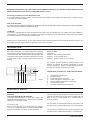
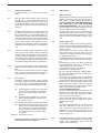
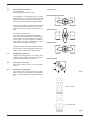
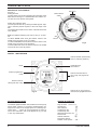
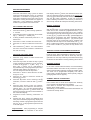
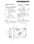
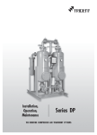
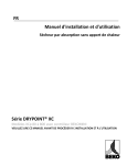
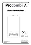
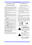
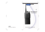
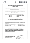
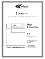
BEFORE ATTEMPTING TO LIGHT APPLIANCE PLEASE MAKE SURE THAT IT IS CHARGED UP WITH WATER WITH THE
NEEDLE POINTING AT 1bar ON THE PRESSURE GAUGE ( 2 Fig.1 )
Gas Safety (Installation and Use) Regulations l998
In your own interests and that of safety, it is the law that all gas appliances are installed and serviced by a competent person
in accordance with the regulation.
GAS LEAK OR FAULT
IF A FAULT OR GAS LEAK IS SUSPECTED, TURN OFF THE APPLIANCE AND CONTACT YOUR INSTALLATION COMPANY,
GAS SUPPLIER OR NEAREST VOKÈRA OFFICE.
LOGBOOK
A log book is supplied with the boiler. This important document must be completed by your installer during the Installation /
commissioning of your boiler. Failure to install and commission the appliance to the manufacturers instructions may invalidate
the warranty. This does not affect your statutory rights.
Please keep your logbook handy, as you will be asked to quote certain information from the log book should you need to contact Vokèra Ltd in the unlikely event of a problem occuring with your boiler.
INTRODUCTION
Your Vokèra Linea Max is a central heating boiler supplying
central heating and instantaneous domestic hot water only.
In the winter when both Central Heating and Hot Water are
needed the central heating circulation stops when hot water
is being drawn off. This normally will not affect the level of
heating.
Any purpose provided ventilation openings must not be
blocked, and should be checked periodically to ensure
this.If the appliance is fitted in a compartment it should not
be used as a storage cupboard (e.g.for food).
2
1
3
NEVER HANG CLOTHES ETC. OVER THE APPLIANCE.
Fig. 1
7
6
5
Boiler Location
Clearances
Minimum - above casing 20mm (3/4in)
Minimum - In front 600mm (24in)
Minimum - At sides 12mm (˚in from casing)
4
1.
2.
3.
4.
5.
6.
7.
Temperature/Fault Indicator.
Pressure Gauge.
Timeclock Aperture (optional).
Status LED green = normal, red = fault
Central Heating Temperature Control knob.
Mode Selector Switch.
Hot Water Temperature Control Knob.
ELECTRICITY SUPPLY
WARNING:
THIS APPLIANCE MUST BE EARTHED
Connection should be made to a 230v 50Hz supply. The
appliance must be protected by a 3amp fuse if a 13amp (BS
1363) plug or fused spur is used.
To connect a plug:
As the colour of the wires in the mains lead to this appliance may not correspond with the coloured markings identifying the terminals in your plug, proceed as follows:-
2
The wire which is coloured green-and-yellow must be connected to the terminal in the plug which is marked with the
letter E or by the earth symbol W or coloured green or
green-and-yellow.
The wire which is coloured blue must be connected to the
terminal which is marked with the letter N or coloured black
The wire which is coloured brown must be connected to the
terminal which is marked with the letter L or coloured red.
Linea Max USERS
1.0
Operation
1.1
OFF Appliance will not activate if tap is turned on
or heating timers/controls are operated. Frost
protection is still active (see 1.3).
1.2
When the mode selector switch is selected (other
than OFF), with no demand for heating or hot
water the appliance will periodically light to
preheat the domestic hot water thermal store.
This is done to ensure that when a demand is
made for domestic hot water the appliance is not
cold, thereby reducing the wait for hot water, and
maximising hot water production.
Fig. 2
If the appliance is unused for 19 hours the motorised valve will operate one cycle, and the pump
will run for a period of 1 minute automatically
(provided the electrical supply to the appliance is
on). This will help prevent these components
becoming stuck if the appliance is not used for
long periods.
1.3
Fig. 3
Frost Protection
The appliance will automatically ignite in central
heating mode if the appliance temperature drops
to approximately 5°C. The appliance will continue
to operate in central heating mode until it reaches
approximately 40°C.
2.0
Hot Water Only
Ensure electricity supply is on. (Status LED indicating green).
2.1
With the boiler mode selector switch (6) turned to
(Fig. 2) the main burner will ignite electronically
whenever water is drawn from the tap.
2.2
Should the boiler fail to ignite the status LED will
flash red (this will be accompanied by an error
code showing at the the fault indicator (1) see 4.0
for list of error codes and remedies. Turn the
mode selector switch (6) to the reset position for
a period of at least 10 seconds then turn back to
the original position before drawing water again.
The appliance will re-attempt ignition. Should
lockout continue the appliance must be checked
by a competent person.
2.3
The maximum water flow rate to the tap is set at
a predetermined maximum delivery. The temperature of water at the tap can be varied by adjusting
the water flow rate at the tap up to the predetermined maximum. The hot water temperature control knob (7) will govern the maximum temperature. Turning the knob clockwise increases the setting, anticlockwise decreases setting. (Fig. 3)
When the appliance is being used in the hot
water mode the temperature/fault idicator (1)
indicates the approximate temperature of the hot
water leaving the appliance.
Fig. 4
Fig. 5
Gas Inlet
Filing loop
Filing/inlet valve
Fig. 6
Linea Max USERS
3
3.0
Heating and Hot Water
Ensure Electricity is on (Status LED showing
green).
3.1
With the boiler mode selector switch turned to
Y Z (fig. 4), ensure either internal timer or
external controls such as time clock and/or room
thermostat are calling for heat. The boiler will now
go through an ignition sequence and the burner
will light.
3.2
Should the boiler fail to ignite and the status LED
(4) flash red, (this will be accompanied by an
error code showing at the the fault indicator (1).
See 4.0 for list of error codes and remedies. Turn
the mode selector switch (6) to the reset position
for a period of at least 10 seconds then turn back
to the original position. The appliance will reattempt ignition. Should the lockout continue the
appliance must be checked by a competent person.
3.3
Adjust the central heating temperature control
knob (5) to suit the weather, turning clockwise to
increase setting, anticlockwise to decrease setting (Fig.5). When the appliance is being used in
the central heating mode the temperature indicator (1) indicates the approximate temperature of
the central heating water leaving the appliance.
N.B
(i) For the quickest heat up of the premises the
highest setting is needed at first, turning down
later.
(ii) When a room thermostat is used, it may be
best to leave the boiler thermostat at a high setting and set the room thermostat as required.
4.0
Error Codes
Should the appliance indicate a lockout (status
LED flashing red), this will be accompanied by an
error code shown in the temperature/fault indicator (2). Error codes could be between 01 - 08:
01
02
03
04
05 to 08
Safety Limits
5.1
System pressure
Ideally the water pressure gauge (2) should read
between 1bar and 1.5 bar when the system is
cold. Leaks or radiator venting will reduce this.
DO NOT UNDER ANY CIRCUMSTANCES USE
THE APPLIANCE WITH THE PRESSURE
GAUGE READING ZERO. Call in your installer or
service engineer if excessive topping up of the
system to restore pressure is necessary.
A built-in safety valve operates if boiler pressure
exceeds 3bar whether hot or cold. If the safety
valve operates (water/steam discharges to drain)
switch off and call your installer or service engineer.
5.2
Restoring Pressure
If the pressure reading on the pressure gauge (2)
falls to below its normal operating pressure (see
clause 5.1) the system/boiler will need repressurising as follows:
Gain access to the interior, push to release the
control panel door, locate the small tool inside
and undo the 2 screws securing the front panel to
the appliance and remove.
a) Identify the filling/inlet valve (found at the base
of the appliance) and C/H Filling Cock. See fig. 6
& 7.
b) The 'filling loop' may have been disconected
from the filling/inlet valve; if so reconnect (fig. 6)
unscrewing the cap as necessary.
c) The filling/inlet valve has 3 positions:
(i) Vertically up - Closed position.
(ii) Turn to the left to horizontal - Filling position.
(iii) Turn to the right to horizontal - Normal operating position. See fig. 7.
To fill, open the C/H Filling Cock and slowly turn
the handle of the filling/inlet valve past the closed
position towards the filling position. Mains water
will be heard to enter the system/boiler. As the
water enters the system/ boiler the pressure
gauge will be seen to rise. Pressurise to between
1bar & 1.5bar when the system is cold.
DO NOT OVERPRESSURISE.
Once the desired pressure is achieved turn the
filling/inlet valve back past the closed position
and into the normal boiler operating position.
Then close the C/H Filling Cock.
d) Disconnect the 'filling loop' (and keep in a convenient and safe place for filling in the future.
Replace cap on valve.
Note:
Occasional repressurisation is a normal part of
care and maintenance carried out by the end
user. However excessive repressurising can be
detrimental to the eventual life span of the
appliance and should be addressed by an installer/service engineer.
5.3
If the appliance water temperature rises too high,
a high limit thermostat operates to extinguish the
burner. This automatically resets when the
appliance cools sufficiently.
Lockout (failure to ignite). Turn mode selector switch to reset position for approximately 10 seconds then back to the original
position.
Overheat. Wait for appliance to cool sufficiently (approximately 15 minutes), then
reset as for code 01.
Problem with fan/flue. Reset as for code 01.
Insufficient water pressure (see 5.1) or poor
flow in system. Check pressure gauge reading (2). If lower than 0.5bar repressurisation is necessary. See 5.2 'restoring pressure'. When pressure is restored reset as
for code 01
Reset as for code 01
Should the appliance continue to lockout, call
your installer or service engineer.
4
5.0
Linea Max USERS
6.0
Shutting Down the System
For short periods:
Turn mode selector switch to 'OFF'
Filing/inlet valve
Normal Operating Position
OFF FI
NG LO
LLI
OP
As described in 1.3 the appliance has an in built
frost thermostat, it is therefore possible that the
appliance will operate in the OFF mode should
the temperature at the appliance fall sufficiently.
BOILER
NG LO
LLI
OP
Filling Position
BOILER
Spare Parts and Servicing
Your Vokèra Linea must be serviced annually.
Please contact your local Vokèra service department, your local gas region or competent installer.
OP
CL
O
9.0
SE
N
PE
Cleaning the Outer Case
Use a clean damp cloth. Do not use abrasive
cleaners.
C/H Filling Cock
O
8.0
NG LO
LLI
Relighting the Appliance
Relight by following steps 2.0 or 3.0 above, after
ensuring that the refilling of the system has been
carried out and the pressure is correct.
OFF FI
Alternatively install a frost thermostat/s to protect
the extremities of the central heating system and
leave the mains electricity and gas turned on.
7.0
BOILER
Turn off the gas cock (fig.8)
Turn off the electricity supply to the appliance.
Open all heating radiator valves and drain through the cocks usually provided at the lowest point
of the system. To ensure draining of radiators,
open radiator air vents remembering to close
them when the operation is complete.
Closed Position
OFF FI
However, if the building is vacated or extremities
of the heating system could be subject to risk of
freezing shut down and drain the system as follows:
Fig. 7
Gas Cock ‘ON’
Gas Cock ‘OFF’
Fig. 8
Linea Max USERS
5
VOKÈRA TIME CLOCKS
MECHANICAL 24 HR VERSION
See Fig. 9
Setting the time.
The time of day can be set by grasping the outer edge of the
black dial and turning it in a clockwise direction until the correct time is in line with the white pointer.
ON Period
Mode selector
switch
Setting the 'switching times'
The 'ON' periods are set by sliding the black tappets, adjacent to the time periods required, to the outer edge of the
dial.
The tappets that remain at the centre of the dial will be the
'OFF' periods.
N.B. The smallest switching time (ON or OFF) is 15 minutes.
To select 'Timed' mode move the selector switch in the
middle of the clock face to the Q position.
To select 'Constant' mode move the selector switch in the
middle of the clock face to the 'I' position.
To select 'Off' mode move the selector switch in the middle
of the clock face to the 'O' position.
OFF
Period
Fig. 9
DIGITAL 7 DAY VERSION
Selects ON/OFF permanently
when in real time (advance)
Winter/Summer
time selector
Reset
Selects programming
mode
Selects hours/minutes for
time of day and programme
times
Selects mode for
setting real time of day
Fig. 10
Selects day or day groups for
real time and programme times
SETTING INSTRUCTIONS
SCREEN INFORMATION
The Vokèra digital timeswitch has, besides the normal group
timing facility, capacity to programme individual daily settings.It has a total of 20 storage spaces for switching operations. Each
space can be programmed as either an
ON or OFF instruction, and can be applied to any one day
or four day combinations.
Days of week 1 2 3 4 5 6 7
ON selection
M
OFF selection
N
Continuously ON
O
Continuously OFF
P
Winter/Summer time +1hr
Timed mode
Q
Override selection
R
Programme spaces
__:__
Number of free spaces
FR
6
Linea Max USERS
BEFORE PROGRAMMING
Press the reset button using a pencil or similar
instrument. This clears the memory of unwanted
information in readiness for programming. The
reset button should be used in the event of local
interference causing the timeswitch to appear to
malfunction. Local interference dependent on
location may be present from time to time.
time display with the Q button, the timeswitch will not activate any switching instruction required for the current time.
You may need to manually select the desired switching state
with the R button. Thereafter, as the unit encounters
further switching instructions in the memory in real time, it
will correctly activate all subsequent switching instructions.
MANUAL OVERRIDE
SET CURRENT TIME AND DAY
1
Press and hold the Q button during operations
2 - 5 below.
2
Press the 'Day' button to select the current weekday ( 1 = Monday, 2 = Tuesday etc.)
3
If setting in British summertime press the +/- 1h
button once.
4
Press the 'h+' button to select the correct hour.
5
Press the 'm+' button to select the correct minute.
6
Now release the Q button - the colon between
the hours and minutes will flash to indicate that
the clock is running.
ENTERING SWITCHING TIMES
1
Press the 'prog.' button to select the first free
memory location.
2
Press the 'Day' button to select the day or group
of days required for switching to occur. You have
a choice of day groups: 1 - 7 (Mon - Sun), 1 - 6
(Mon - Sat), 1 - 5 (Mon - Fri), 6 - 7 (Sat & Sun),or
any individual day. Each programme space automatically starts with the day selection 1 - 7.
You can change this with the day button.
3
Press the 'h+' button to select the hour the switching is to occur.
4
Press the ‘m+’ button to select the minute the
switching is to occur.
5
Press the R button once to select an ON M
instruction, or twice to select an OFF N instruction.
6
Press the 'Prog.' button to store your programmed information, and select the next free programme space. Or if you have finished loading
the programme press the Q button which will
save the programme and return the timeswitch to
the current time display.
7
Programme further switching instructions as
above.
8
Pressing the 'Prog.' button one additional time
after you have finished programming displays the
remaining number of programme spaces that are
free, e.g. 'Fr 12'. If all programme spaces are full,
'Fr 00' will appear.
With the R button you can manually operate the switch to
switch ON or OFF outside the programmed times, or you
can put the switch into a permanent ON or OFF condition.
The first press of the R button advances the output to ON
or OFF (M or N together with the R symbol displayed to
show that the programme has been overridden) without
disrupting the programme sequence. The second press
fixes the output in the continuously ON O condition. The
third press fixes the output in the continuously OFF P condition. In either fixed condition, the timeswitch will only revert
to the timed condition if you press the R button once
more.
READ OR CHANGE PROGRAMMED INFORMATION
Press the 'Prog.' button repeatedly to view each of your programmed instructions in the order in which they were programmed. You can stop to alter any of the instructions using
the buttons as described in 'entering switching times' above.
RUNNING RESERVE
In the case of mains electrical failure, the internal battery
will ensure that the actual time of day continues to operate
and that the automatic switching programme remains intact.
The clock can be programmed completely even without
mains supply, provided the battery back up is fully charged.
(Charging time 70 hours approx.)
SUMMER / WINTER CHANGEOVER
From summer time to winter time: Depress the +/-1h key
once (symbol +/-1h disappears from display).
From winter to summer time: Depress the +/-1h once.
Display shows +/-1h symbol).
Alternatively you can follow the instructions described in 'set
current time and day' above.
Important Note: After programming is complet
ed, and you return the timeswitch to the current
Linea Max USERS
7
(Cod.066612)
VER 07/02
Vokèra Ltd.
Web: www.vokera.co.uk
Southern Region: Morson Road, Enfield, Middlesex EN3 4NQ. Sales: 020 8216 6300. Fax: 020 8805 6320.
Parts: 020 8216 6310. Technical HeIpIine: 01274 866110. Customer Services: 0870 333 0220.
E-mail: [email protected]
Northern Region: Stubs Beck Lane, West 26 Business Park, Whitehall Road, Cleckheaton, West Yorkshire BD19 4TT. Sales: 01274 866100.
Fax: 01274 865557. Parts: 01274 866140. Technical HeIpIine: 01274 866110. CustomerServices: 0870 3330220.
E-mail: [email protected]
Scottish Region: Shuna Street, Maryhill, Glasgow G20 9NW. Sales: 0141 945 6800. Fax: 0141 945 5136.
Parts: 0141 945 6820. Technical HeIpIine: 0141 945 6810. Customer Services: 0870 333 0220.
E-mail: [email protected]
Vokèra (Ireland) Ltd: West Court, CaIIan, Co. Kilkenny, Ireland. Sales/Parts: 056 55055.
Fax: 056 55060. Technical HeIpIine/ Customer Services: 056 55057.
E-mail: [email protected]
Vokèra Ltd. reserve the right to change the specifications without prior notice. Consumers’ statutory rights are not affected.