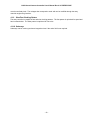
1
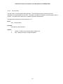
NSO Infrared Camera Controller User's Manual Rev 0.13 PRERELEASE
NATIONAL SOLAR OBSERVATORY
NEW ARRAY CAMERA
(NAC)
AN INFRARED ARRAY CONTROLLER
AND DATA ACQUISITION SYSTEM
USER'S MANUAL
REVISION 0.13
3/10/05
-1-
NSO Infrared Camera Controller User's Manual Rev 0.13 PRERELEASE
Prepared by Mauna Kea Infrared, LLC
-2-
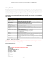
NSO Infrared Camera Controller User's Manual Rev 0.13 PRERELEASE
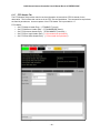
Revisio
n
0.13
0.12
Author
Revision History
Summary of revisions
Date
Mike
Thompson
Corrected 5s exposure time instrumental feature. Changed
engineering password references to Operator's Manual.
Added general use scenario section.
3/10/05
Mike
Thompson
Added requirements list. Added coordinate description. Added
filter wheel description. Added optics description. Made
clarifications to clocking patterns. Added single and CDS read
descriptions. Did a general cleanup. Expanded Double
Sampling description and added diagram.
2/24/05
This version contains unresolved issues and questions.
DT issues marked with (TODO DT)
0.11
Mike
Thompson
Moving Operator's Manual content out of this User's Manual.
Added some other editing notes that are to do. Expanded
Instrument Description. Changed title page name and layout.
2/17/05
0.10
Mike
Thompson
Initial revision, mostly a template.
2/8/05
Prepared TOC and Title Page. Integrated command set from
Software Array Control document. Some content may be more
relevant in the Operator's Manual per the NAC SOW.
-3-
NSO Infrared Camera Controller User's Manual Rev 0.13 PRERELEASE
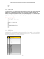
Table of Contents
1Introduction...........................................................................................................................8
1.1Related Documents.......................................................................................................................................8
2Science Description.............................................................................................................9
2.1High-Speed Polarimetry................................................................................................................................9
2.2Dithering........................................................................................................................................................
9
2.3References....................................................................................................................................................
9
2.4Science Channel Performance...................................................................................................................10
3Instrument Description......................................................................................................11
3.1Instrumental Specifications.........................................................................................................................13
3.1.1FPA Mount Specifications....................................................................................................................13
3.1.2FPA Control Specifications..................................................................................................................13
3.1.3Communication and User Interface Specifications..............................................................................13
3.1.4Data Acquisition and Storage Specifications.......................................................................................13
3.2Instrument Overview...................................................................................................................................14
3.2.1Optics and Light Path Description........................................................................................................14
3.2.2Filter Wheel Description.......................................................................................................................15
3.2.3Detector Properties..............................................................................................................................15
3.2.4Coordinate System Description............................................................................................................16
3.2.5Electronics Description.........................................................................................................................17
3.2.5.1Instrument Control Electronics......................................................................................................17
4Important Aspects of Operation.......................................................................................19
4.1Basic Image Acquisition Concepts.............................................................................................................19
4.1.1Resets...................................................................................................................................................19
4.1.2Noise Reduction with Pedestal Frames and Correlated Double Sampling.........................................20
4.1.3Single Reads........................................................................................................................................
21
4.1.4Coaddition.............................................................................................................................................21
4.1.5Coaddition (Rabin Mode) ....................................................................................................................21
4.1.6Noise Reduction Reads (NDR Reads).................................................................................................21
4.1.7Synchronized Start...............................................................................................................................21
4.1.8Well Depth............................................................................................................................................
21
4.1.9Slow/Fast Clocking Pattern..................................................................................................................22
4.1.10Subarrays...........................................................................................................................................
22
4.2Array Clocking Patterns..............................................................................................................................23
4.2.1Clocking Pattern Building Blocks, pFiles and patFiles........................................................................23
4.2.1.1pFile Format...................................................................................................................................24
4.2.1.2patFile Format................................................................................................................................25
4.2.1.3Bit Definitions.................................................................................................................................25
4.2.1.4The cpat Utility...............................................................................................................................27
4.2.2pFiles and patFiles Shipped with the NSO Array Controller................................................................28
4.3User Programmable Array Bias Voltages...................................................................................................29
5Observing with NAC...........................................................................................................30
5.1Preparation for Observing...........................................................................................................................30
5.1.1Pre-Run Planning.................................................................................................................................30
5.1.2Daytime Camera Setup, Calibration and Checkout.............................................................................30
5.2Night-Time Calibration and Setup...............................................................................................................31
5.2.1Twilight Setup ......................................................................................................................................
31
5.2.2Flats with Facility Calibration Unit........................................................................................................31
5.2.3Sky Flats...............................................................................................................................................
32
5.3Science Observations: Modes and Scenarios............................................................................................33
5.3.1General Use Scenario..........................................................................................................................33
5.3.2TTL Sense Line Synchronized Start....................................................................................................33
-4-
NSO Infrared Camera Controller User's Manual Rev 0.13 PRERELEASE
5.3.3Single Read Procedure........................................................................................................................34
5.3.4Correlated Double Sample Read Procedure.......................................................................................34
5.3.5Coaddition Procedure...........................................................................................................................34
5.3.6NDR Procedure....................................................................................................................................34
5.3.7Streaming Image Capture Procedure..................................................................................................34
5.3.8Remote Operation................................................................................................................................34
5.3.9Standalone Operation..........................................................................................................................34
5.3.10Astrometry..........................................................................................................................................34
5.3.10.1Methods to get the Centroid of the Primary................................................................................34
5.4Night-time Shutdown...................................................................................................................................35
5.5Preliminary Data Reduction........................................................................................................................35
5.5.1Mapping of Arrays to Each Other.........................................................................................................35
5.5.2Sky Subtraction and Dark Current Subtraction....................................................................................35
5.5.3Flat Fielding..........................................................................................................................................
35
5.5.4Frame Differencing...............................................................................................................................35
6Array Control Commands and the Array Control GUI....................................................36
6.1Array Control GUI........................................................................................................................................37
6.1.1Common Functions..............................................................................................................................37
6.1.2Observation Tab ..................................................................................................................................38
6.1.3Setup Tab.............................................................................................................................................
40
6.1.4Engineering Tab...................................................................................................................................41
6.1.5Macro Tab.............................................................................................................................................42
6.1.6System Tab .........................................................................................................................................
44
6.1.7FITS Header Tab..................................................................................................................................46
6.2System Setup Commands..........................................................................................................................47
6.2.1PsrvHostname – Set Pixel Server Hostname......................................................................................47
6.2.2PsrvPortNum – Set Pixel Server Port Number....................................................................................47
6.2.3ClockerHostname – Set Clocker Hostname........................................................................................47
6.2.4ClockerPortNum – Set Clocker Port Number......................................................................................47
6.2.5PixelHostname – Set Pixel Software Host...........................................................................................47
6.2.6PixelPortNum – Set Pixel Software Port Number................................................................................47
6.2.7DigiHostname – Set DigiPort Hostname..............................................................................................49
6.2.8DigiPortNum – Set DigiPort Port Number............................................................................................49
6.3System Commands.....................................................................................................................................49
6.3.1Connect – Connect IC to Clients..........................................................................................................49
6.3.2Go – Start Image Acquisition...............................................................................................................49
6.3.3Stop – Stop Image Acquisition.............................................................................................................49
6.4General Setup and Configuration Commands...........................................................................................50
6.4.1ArcMode - Set Exposure Mode............................................................................................................50
6.4.2Array – Set Subarray Size....................................................................................................................50
6.4.3ArrayMode – Set Array Mode (Full, Subarray)....................................................................................50
6.4.4AutoSave – Set Save/Discard Data.....................................................................................................50
6.4.5BgrEnable – Background Reset Enable..............................................................................................51
6.4.6BgrMs – Set the BGR MS Parameter..................................................................................................51
6.4.7BgrMinMs – Set the BGR Min.MS Parameter.....................................................................................51
6.4.8BgrNs – Set the BGR NS Parameter...................................................................................................51
6.4.9CamMode – Set Basic/Streaming Camera Mode................................................................................51
6.4.10ClkBiasVGGCL – Set VGGCL Bias Voltage......................................................................................53
6.4.11ClkBiasVDETL – Set VDET Bias Voltage..........................................................................................53
6.4.12Coadd – Set Coadd Count.................................................................................................................53
6.4.13Cycles – Set Cycle Count..................................................................................................................53
6.4.14DoFastMode – Select Fast or Slow Clocking....................................................................................53
6.4.15EPassword – Send Engineering Password.......................................................................................54
-5-
NSO Infrared Camera Controller User's Manual Rev 0.13 PRERELEASE
6.4.16FitsComment – Set the FITS Comment Header................................................................................54
6.4.17FitsFilename – Set FITS Filename....................................................................................................54
6.4.18FitsFilenumber – Set FITS File Number............................................................................................54
6.4.19ITime – Set Integration Time..............................................................................................................54
6.4.20NDR – Set Non-Destructive Read Count...........................................................................................55
6.4.21SlowCnt – Set Slow Count.................................................................................................................56
6.4.22DestBuf – Set the Image Destination Buffer......................................................................................56
6.4.23FitsObject – Set FITS Object Header Entry.......................................................................................56
6.4.24FitsObserver – Set FITS Observer Header Entry..............................................................................56
6.4.25RTVEnable – Enable High Speed Real Time Viewing......................................................................56
6.4.26SavePath – Set FITS File Path..........................................................................................................56
6.4.27SerialEnable – Enable Serial Communication...................................................................................57
6.4.28ReadSerial1 – Read Serial Port 1......................................................................................................57
6.4.29ReadSerial2 – Read Serial Port 2......................................................................................................57
6.4.30WriteSerial1 – Write to Serial Port 1..................................................................................................57
6.4.31WriteSerial2 – Write to Serial Port 2..................................................................................................57
6.4.32TimestampEnable – Enable Timestamping.......................................................................................57
6.5Data Viewer Commands.............................................................................................................................58
6.5.1DV1Enable – Enable Data Viewer 1....................................................................................................58
6.5.2DV2Enable – Enable Data Viewer 2....................................................................................................58
6.5.3DV1Hostname – Set Hostname for Data Viewer 1..............................................................................58
6.5.4DV2Hostname – Set Hostname for Data Viewer 2..............................................................................58
6.5.5DV1Port – Set the Port Number for Data Viewer 1.............................................................................58
6.5.6DV2Port – Set the Port Number for Data Viewer 2.............................................................................60
6.6DV: Data Viewing and Arithmetic Operations.............................................................................................60
7Setup and Operation..........................................................................................................61
7.1Start-up Procedure......................................................................................................................................61
7.2System Checkout........................................................................................................................................
61
7.3Temperature Monitoring While in Use........................................................................................................61
7.4Shutdown Procedure...................................................................................................................................61
8Basic Troubleshooting......................................................................................................62
8.1Electronics Troubleshooting........................................................................................................................62
8.2Array Troubleshooting.................................................................................................................................62
8.2.1Photoemissive Defects.........................................................................................................................62
8.3Temperature Troubleshooting....................................................................................................................62
8.4Vacuum Troubleshooting............................................................................................................................62
9Acronyms and Definitions.................................................................................................63
-6-
NSO Infrared Camera Controller User's Manual Rev 0.13 PRERELEASE
Table of Figures and Photos
Figure 1Functional Block Diagram of the NAC Instrument.............................................11
Figure 2NAC Optical Diagram.............................................................................................14
Figure 3NAC Optical Distances Diagram...........................................................................15
Figure 4Population of the Filter Wheel..............................................................................15
Figure 5Table of NAC Detector Properties........................................................................16
Figure 6Block Diagram of Major NAC Components.........................................................17
Figure 7Block Diagram of Instrument Control Electronics.............................................18
Figure 8Background Reset Timing Diagram.....................................................................19
Figure 9Illustration of Correlated Double Sampling's Pedestal and Signal Frames.....20
Figure 10Illustration of a Single Read................................................................................21
Figure 11Table of pFile Commands...................................................................................24
Figure 12Table of Bit Definitions for Clock Signals.........................................................26
Figure 13Table: pFiles and Their Specific Array Operations..........................................29
Figure 14Screen Capture: Array Control GUI Common Function Buttons....................37
Figure 15Screen Capture: Array Control GUI Command Line and Status ....................37
Figure 16Screen Capture: Array Control GUI Observation Tab......................................38
Figure 17Screen Capture: Array Control GUI Setup Tab.................................................40
Figure 18Screen Capture: Array Control GUI Engineering Tab......................................41
Figure 19Screen Capture: Array Control GUI Macro Tab................................................42
Figure 20Screen Capture: Array Control GUI System Tab..............................................44
Figure 21Screen Capture: Array Control GUI FITS Header Tab......................................46
-7-
NSO Infrared Camera Controller User's Manual Rev 0.13 PRERELEASE
1 Introduction
This is the User's Manual for NSO's New Array Camera (NAC), an Infrared Array Controller and Data
Acquisition instrument, designed and built by Mauna Kea Infrared. This manual is meant to describe the
instrument for observational purposes. The Operator's Manual covers instrument setup, maintenance, and
troubleshooting procedures for NAC. This document provides a description of the instrument and its
components, and how to observe with NAC.
NAC is an imaging facility instrument. (TODO DT: Write some slick scientific background of infrared imagery
and how it will advance the science goals of NSO. What is unique about this instrument?) From the very
beginning, its design has been optimized to address this purpose with little compromise.
(TODO MT: Search and replace on "NICI".)
(TODO MT: Update and verify the Section descriptions.)
Section 2 provides a science description of the instrument.
Section 3 gives an overview of the NAC instrument and it functional specifications
Section 4 describes important observational issues. All users should be familiar with this section.
Section 5 describes operational issues and procedures that every observer should read.
Section 6 describes data viewing and operation of the Array Controller through the GUI and via textual
commands.
Section 7 describes instrument setup and operation procedures.
Section 8 provides information on basic troubleshooting.
Section 9 defines acronyms and definition of terms used throughout this document.
Appendix A gives the physical specifications of the filters.
1.1
Related Documents
The NAC User Manual has several documents that are included as addendums. These addendums address
the use and operation of parts of the NAC instrument.
•
•
NAC User Manual Addendum, Data Viewer (DV) Description: A description of a tool used for
viewing and manipulating images.
NAC Software Array Control and Image Acquisition: A description of the array control software
and GUI for specific array configuration and operation.
-8-
NSO Infrared Camera Controller User's Manual Rev 0.13 PRERELEASE
2 Science Description
(TODO DT: Write an introduction. Are there any subsections missing?)
2.1
High-Speed Polarimetry
(TODO DT) This description is leveraged from the SOW. Is this adequate and relevant?
Solar spectropolarimetry makes two key instrumental demands: high signal-to-noise and rapid cadence. High
signal-to-noise is required because the observed range of polarization is 10-2 to 10-4 or below. Rapid cadence
is a related requirement, because net polarization is determined by subtracting images in opposite states of
polarization (e.g., right and left circular polarization). Atmospheric turbulence (“seeing”) degrades the
difference signal if the two states are obtained sequentially. Therefore, NAC supports a fast frame rate.
Additionally NAC provides the ability to co-add a number of difference images to achieve the required
polarization sensitivity. The number of co-adds used by observers will depend on the noise in the individual
frames and must balance precision against the total time required to scan a useful area of the solar surface.
A distinctive aspect of spectropolarimetry is the need for multiple co-add buffers. If a slit spectrograph is used
in conjunction with spatial scanning, at least six buffers are needed to measure the four Stokes parameters (I,
Q, U, V) that characterize the polarized light at each slit position, namely I+V, I-V, I+Q, I-Q, I+U, and I-U). If a
tunable filter is used (full-field imaging with sequential wavelength scanning), the line must be scanned rapidly
(interleaved with polarization modulation) so that differential seeing does not distort the line profile. The
number of buffers will depend on the number of wavelength positions in the line. Four wavelength positions
(about the minimum needed, allowing for Doppler shifts of the line position) will require eight co-add buffers to
measure one Stokes parameter (e.g., I+V, I-V).
2.2
Dithering
(TODO DT: Write this section. This information is an example from the NICI instrument.)
Since good flat fielding is very important to the data quality from NICI a provision has been made for small
dithers in one dimension. Dithering with NICI is a complex matter however. Once the AO loop is turned on
the AO system will keep the star on the mask even if the telescope is moved so offsetting the telescope will
not affect a dither. To dither the steering mirror in the AO wavefront sensor must be tilted to offset the AO
guide point. The focal plane mask must be moved in a coordinated move to put the mask at the new star
position. Dithers are expected to be only on the order of 1 arcsecond since the radius of the field is only 9
arcseconds. The focal plane mask is mounted in a wheel and is moved by rotating the wheel, thus dithers
can only be done in one dimension and will follow a slight arc. This will all be handled in the software but the
observer should be aware that dithers will be only possible along this arc.
2.3
References
(TODO DT: include any references.)
-9-
NSO Infrared Camera Controller User's Manual Rev 0.13 PRERELEASE
2.4
Science Channel Performance
(TODO DT: Write this section.)
- 10 -
NSO Infrared Camera Controller User's Manual Rev 0.13 PRERELEASE
3 Instrument Description
NAC is a cryogenic 1 - 5 ?m imager implemented with a 1024x1024 Aladdin III array. The science channel
has a 6 position filter wheel that is initially populated with J, H, CO, 4mic, and HE1083 filters. Image capture
can be synchronized with external devices by a TTL sense line input into the Array Controller.
In nighttime astronomical applications, an infrared instrument and its detectors are typically an integrated,
single-purpose unit. NAC's camera and its controller are designed to interface with different types of external
optical systems and specialized instrument control programs, current and planned. The camera will be used
both directly at the focal plane of solar telescopes and at the exit port of imaging spectrographs.
The key instrumental elements are:
• A proven array controller platform that integrates temperature and mechanism control.
• One 1024x1024 InSb Aladdin III Detector operating over the 1-5 micron with range with high density
sampling at 0.018 (TODO DT verify this number.) arcsec/pixel.
• A 6 position filter wheel that provides users a choice of filters in the science channel.
• Low scatter, Ghost-Free Optics. The all-reflective optical train is designed to minimize the number of
surfaces and eliminate ghosts.
• Closed-cycle cryogenic cooling.
• 1 TTL-compatible sense line input for synchronizing with external devices.
The key instrumental features are:
• Fast frame rate (10 Hz minimum).
• Up to 5s exposure time and greater.
• Full array or sub-array readouts.
• Single and Correlated Double sampling (Did optional Fowler sampling make it???).
• 8 frame buffers.
• Image monitor.
• FITS file format support.
• Streaming and co-addition modes.
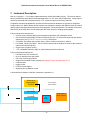
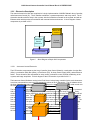
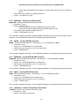
A functional block diagram of the NAC instrument is provided in 3.
Telescope or
Spectrograph
Exit Port
Image Capture
Synchronization
Cryostat/Camera
Filter Wheel
Fold Mirror
Instrument &
Array Control
IR
Array
- 11 -
NSO Infrared Camera Controller User's Manual Rev 0.13 PRERELEASE
- 12 -
NSO Infrared Camera Controller User's Manual Rev 0.13 PRERELEASE
3.1
Instrumental Specifications
This section lists all of the specifications of the NAC instrument and should be useful for readers wishing to
gain a quick understanding of the functionality of the instrument. These specifications are from the final set of
requirements defined the in the Acceptance Checklist in NSO's Redstar3 Array Controller Acceptance Test
Plan's.
3.1.1
FPA Mount Specifications
FPA socket and fanout board, housing, fiberglass supports and mounting bracket
Cabling and connectors (lab test cabling)
Cryo wiring and connectors
Electrically shielded
Baffled against stray light
Temperature sensor
Heating (for active temperature control and warmup)
Temperature controller
3.1.2
FPA Control Specifications
Operate Raytheon Aladdin III 1024 × 1024 FPA
Fastest fame rate: 10 Hz (minimum, Single Read) –15 Hz (target) (Single Read)
Maximum exposure time: ? 5 s
All operations supported on either full array or single user-specified subarray
Global reset mode
Sampling modes
Single
Correlated double
Fowler (optional) (Is Fowler sampling supported???)
Readout noise: using correlated double sampling, readout electronics to contribute ? 25% to readout noise of FPA +
readout electronics system at 1Hz frame rate
User-programmable timing parameters
Resistant to electrical interference
FPA temperature selectable in range 30–50 K
Readout of FPA temperature accurate to ±2 K
FPA temperature stable to ±0.1 K over 6 hours
3.1.3
Communication and User Interface Specifications
1 TTL-compatible sense line, electrically isolated
2 RS-232 full-duplex serial ports (for filter wheel control)
10/100 Ethernet connection for camera commands
Stand-alone mode with graphical user interface and data display
Remote Mode via Unix Socket
Communication over networks via ASCII command sequences
Image monitor with gain and offset correction
Non-co-add mode: 6 Hz (minimum single read, no gain or offset correction) –
12 Hz (target, single read) refresh rate
3.1.4
Data Acquisition and Storage Specifications
Support Flexible Image Transport System (FITS) data format including header parameters, comments, and image
extensions
All modes to operate either with or without writing data to disk
Streaming mode - Record full or sub-sampled images on disk as fast as possible (5 image s-1 minimum single read,
10 image s-1 target, single read)
Co-addition mode - Co-add 16-bit data into 8 (minimum) – 16 (target) named, user selectable, 32-bit buffers
- 13 -
NSO Infrared Camera Controller User's Manual Rev 0.13 PRERELEASE
All modes executable via user written macros
3.2
Instrument Overview
NAC is a cryogenic 1 - 5 ?m imager implemented with a 1024x1024 Aladdin III array. The science channel
has a 6 position filter wheel that is initially populated with J, H, CO, 4mic, and HE1083 filters. NAC will
generally be fed light from a spectrograph. The camera will be used both directly at the focal plane of solar
telescopes and at the exit port of imaging spectrographs. (Need we include any warnings about flux
levels???)
(TODO DT: Description of the science goals (co-addition) and how the instrument supports the goals.)
3.2.1
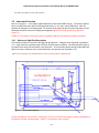
Optics and Light Path Description
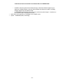
This section provides an overview of the light path through NAC. A diagram of the light path is provided in
3.2.1. Light enters the cryostat through a Calcium Fluoride entrance window. The beam passes through a
six position filter wheel and encounters a gold fold mirror. Then the beam passes through a light baffle and
falls on the array. Distances of the various elements in the light path are illustrated in 3.2.1.
(Where is focal plane to be located relative to the cryostat (entrance window)???)
OUTDATED???
DETECTOR
LIGHT BAFFLE
ENTRANCE WINDOW
FOLD MIRROR
FILTER WHEEL
Figure 2
NAC Optical Diagram
(These two diagrams are from NAC_8-26-03.ppt. They may not reflect the changes to reduce the distance to
the detector from the cryostat window. TODO: DT is checking on the currency.)
- 14 -
NSO Infrared Camera Controller User's Manual Rev 0.13 PRERELEASE
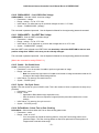
OUTDATED???
Figure 3
NAC Optical Distances Diagram
The filter wheel has 6 positions that are populated with 2" square and 1" round filters as shown in the table in
3.2.2.
3.2.2
Filter Wheel Description
NAC has a filter wheel mechanism that will be controlled by the Observer to configure the instrument for a
given observation.
The list below indicates the planned initial population of filters in the filter wheel. Note that NSO may change
the population of the filter wheel during or after commissioning.
Position
HOME
2
3
4
5
6
Figure 4
3.2.3
Filter
J
H
CO
4mic
H
He1083
Footprint
2" Square
2" Square
1" Round
1" Round
1" Round
1" Round
Population of the Filter Wheel
Detector Properties
Read Noise (single read)
Read Noise (Fowler sampling)
Frame rate
Average Dark Current
TBD (TODO DT)
TBD
TBD
TBD
- 15 -
NSO Infrared Camera Controller User's Manual Rev 0.13 PRERELEASE
Well Size
TBD
Figure 5
3.2.4
Table of NAC Detector Properties
Coordinate System Description
(TODO DT: Describe how the coordinates in the IC system's coordinates relate to telescope coordinates.)
- 16 -
NSO Infrared Camera Controller User's Manual Rev 0.13 PRERELEASE
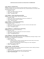
3.2.5
Electronics Description
The control electronics in NAC are comprised of a single implementation of MKIR's Redstar3 Array Controller,
called Instrument Control (IC). The IC handles mechanism, cryostat temperature, and array control. The IC
electronics interface with the array in the cryostat, with the mechanism mounted on the cryostat, and with an
Ethernet switch which permits communication with external devices and servers. A block diagram of these
components is provided in 3.2.5.
Motors and
Interface
Instrument
Control
Electronics
Cryostat
Assembly
Ethernet Switch
Figure 6
3.2.5.1
Block Diagram of Major NAC Components
Instrument Control Electronics
The IC Electronics components are the Array Controller (Array Control Chassis), a mechanism Junction Box
(JBox), a mechanism Utility Box (UBox), a Pixel Server (PS), an Array Power Supply (APS), and an Ethernet
switch. These electronics are responsible for array control, mechanism control, thermal conditioning of the
cryostat, and image acquisition. A block diagram of the IC Electronics is provided in 3.2.5.1.
The Instrument Control Software running in the Pixel Server is the primary controller for the entire instrument.
It receives commands from users and orchestrates the actions of the IC Electronics. The IC Software drives
the Array Controller, provides instructions for data handling to the instrument, and provides serial control over
the mechanism and temperature control subsystem.
Hall Sensor
The Array Controller is responsible for array control, clocking, and readout. The Array Controller is powered
with a dedicated Array Power Supply which also powers the arrays through the Array Controller. Array
clocking control is provided by digital clock signals converted to analog levels in the Array Controller and fed
to the arrays in the Cryostat. The resulting analog array readout data are amplified and converted to digital
pixel data by the Array Controller. The digital pixel data is fed from the Array Controller to the Pixel Server
over a high speed fiber optic link. The IC Server is a server class multi-processor PC-based computer. The
Pixel Server assembles the pixel data into frames and prepares the frames for writing to local disk storage.
Mechanism control is driven from the IC Software running on the Pixel Server over the internal LAN to a
terminal server in the Mechanism Utility Box. The UBox bundles power and serial control lines into one
Position Cable for the Filter Wheel mechanism. A Junction Box mounted on the Cryostat Assembly routes
the mechanism power and control lines from the Position Cable to the Filter Wheel cable.
- 17 -
NSO Infrared Camera Controller User's Manual Rev 0.13 PRERELEASE
The IC Software in the Pixel Server also provides serial control over the Temperature Control subsystem via
the internal LAN and terminal server. A Lakeshore 332 Temperature Controller is used to maintain the
detector temperature and provides information about the health of the cooling system in the cryostat to the IC
Server.
Ext Trig Array
Utility
Box
Optical
Array
Pixel
Controller
Power
Server
SupplyFiber
Ethernet
Hall Sensor
Utility Box
Position
Lakeshore
Maint/Config
5V Array
P1
P2
GND Cable
Mechanism
Motor
Filter
Junction Box
Wheel
Array
Filter
Position
Wheel
Mechanism
Junction
Box
Lakeshore
Ethernet
Switch
Cryostat
Ext Trig
5V GND
Array Controller
P1 Array Cable
P2 Array Cable
Optical
Fiber
Pixel Server
Maint/Config
Facility LAN
Figure 7
Motor
Array Power
Supply
Block Diagram of Instrument Control Electronics
- 18 -
Array
NSO Infrared Camera Controller User's Manual Rev 0.13 PRERELEASE
4 Important Aspects of Operation
(TODO DT: Write this section. This information is an example from the NICI instrument.)
(TODO MT: Scan whole document for references to old commands. Charles is updating the implemented
commands, which have all changed.)
NAC was designed first and foremost as an instrument to do high-speed polarimetry. The purpose of this
section is to highlight aspects of NAC that should be considered by observers when planning to use NAC for
their observations. These aspects will be primarily discussed as concepts, not giving specific commands.
Specific operational procedures and commands are provided in Sections 5 and 6.
(TODO DT: Rewrite this section. This information is an example from the NICI instrument.)
Since NICI has very small pixels the integration times will not be very short. At shorter wavelengths
integration times will be on the order of 1 to 2 minutes. In the thermal wavelengths the integration times will
be more on the order of 1 to 2 Hz. Since very fast integrations are not required there are not very many
options that must be adjusted in the array controller. The issues that an observer needs to be concerned with
are listed below.
4.1
Basic Image Acquisition Concepts
This section describes some basic concepts related to image acquisition.
4.1.1
Resets
During times in which images are not being acquired, light may still be falling on the array. The resulting
accumulation of electrons in the wells of the array will overexpose the image and may aberrations in
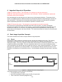
subsequent images. The Array Controller will flush these extra electrons at continual and specific times. This
is called a background reset (BGR). There are 3 parameters that can be set to control background resets.
The first parameter, NS, specifies the time for which the reset line, Vrstg, is held high (asserted). The second
parameter, MS, specifies the time between BGRs. The last parameter, Min.MS, specifies the time from the
last BGR to the beginning of the acquisition process. A timing diagram showing these parameters is provided
in 4.1.1.
Vrstg
NS
MS
Min.MS
Image
Acquisition
Figure 8
Background Reset Timing Diagram
The Image Acquisition process consists of the following
• First a global reset is executed.
• Next comes a pedestal readout, except for ARC_S single reads.
• Then a wait time is executed (integration time).
- 19 -
NSO Infrared Camera Controller User's Manual Rev 0.13 PRERELEASE
•
Finally comes the signal readout.
The additional reset just before the image acquisition is so an exact duration of integration is known. The
time of integration of any particular pixel depends on how many pixels are ahead of it in the scan sequence
as well as how fast each pixel can be scanned. This information can be computed downstream if needed.
For single reads only the time between last reset and first pixel acquisition is used to compute the duration of
integration. For double reads integration time starts with the first pixel of the pedestal readout.
4.1.2
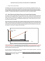
Noise Reduction with Pedestal Frames and Correlated Double Sampling
One source of noise in image capture is due to low frequency DC drift. Another source of noise results from
the fact that when an Aladdin III device is (global) reset to clear excess electrons, the reset can leave small
number of electrons in the wells of the imaging array. Noise from the excess electrons and DC drift noise in
an image can be reduced by using Correlated Double Sampling (CDS). CDS is referred to as arc_D in the
Array Control GUI and commands.
CDS employs the use of a Pedestal Frame recorded immediately after the reset operation preceding image
capture. The Pedestal Frame is then subtracted from the subsequent Signal Frame. This removes the noise
in the Signal Frame (image frame) resulting from any excess electrons left in the well after the reset. Since
DC drift occurs over time scales much longer than typical integration times DC drift noise is also removed in
the subtraction. This results in a sharper, less noisy image.
Signal Frame
Pedestal Frame
Well
Reset
Voltage
Integration Time
Time
Figure 9
Illustration of Correlated Double Sampling's Pedestal and Signal Frames
In NAC the Pedestal Frame scan is taken after the ‘rtime’ parameter (???Is this rtime still settable? Verify that
it is still named the same.). Subsequent Image Frame scan(s) will have this data subtracted out. Usually, if
not always, each reset may need a separate pedestal. Note that subarray specifications will not change
between pedestal and subsequent scans.
Over the integration time high frequency noise is not correlated, it occurs at higher frequencies. So CDS can
lead to an increase (? ?2) in high frequency noise.
Reference: Raytheon Infrared Center of Excellence, Aladdin II and III 1024 x 1024 IRFPA User's Guide and
Operation Manual, Preliminary, undated.
- 20 -
NSO Infrared Camera Controller User's Manual Rev 0.13 PRERELEASE
4.1.3
Single Reads
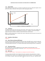
Image capture with a single read (arc_S) consists of a global reset of the array, waiting the integration time to
permit accumulation of electrons in the array wells, and an image (signal) readout.
Signal Frame
Well
Reset
Voltage
Integration Time
Time
Figure 10
4.1.4
Illustration of a Single Read
Coaddition
In coaddition multiple scans of the same image may be taken. Before each scan the array is globally reset.
These scans result in data that is accumulated into a single buffer. Coaddition is useful when capturing
images at a high rate and there is a desire to minimize the number of saved frames.
Note: An excessively high number of coadds could create an image that would exceed the 32 bit range of the
integer based storage buffers.
4.1.5
Coaddition (Rabin Mode)
(TODO DT)
4.1.6
Noise Reduction Reads (NDR Reads)
The array controller is capable of multiple non-destructive reads, called NDR reads, to reduce the read noise.
When performing NDR reads multiple reads are made from the array without resetting the array. This results
in one frame with lower read noise. The number of NDR reads can be set through the GUI or command line.
4.1.7
Synchronized Start
NAC is equipped with a hardware triggered science array controller so that image capture can be
synchronized with external events by a TTL sense line. (TODO: Verify and add more details about NAC's
synchronization scheme.)
4.1.8
Well Depth
(TODO DT: Write this section. This information is an example from the NICI instrument.)
For most operations with NICI a low well depth will be used to optimize the array performance. At longer
wavelengths such as L and M or for very bright stars deeper wells will be required. The well depths provided
are low, medium, and high. Selecting a well depth changes the reset level on the array. Large wells create
- 21 -
NSO Infrared Camera Controller User's Manual Rev 0.13 PRERELEASE
more hot and bad pixels. The voltages that correspond to each well can be modified through the array
controller engineering interface.
4.1.9
Slow/Fast Clocking Pattern
The array controller is capable of fast and slow clocking patterns. The fast pattern is optimized for speed and
has increased noise. The Slow pattern is optimized for low noise
4.1.10 Subarrays
Subarrays can be used to get shorter integration times if the entire field is not required.
- 22 -
NSO Infrared Camera Controller User's Manual Rev 0.13 PRERELEASE
4.2
Array Clocking Patterns
There are 16 signals that are used in this Redstar3 implementation for controlling the Aladdin III array. The
term used to describe these signals is “clock” although some of the signals may be constant voltages. It is by
manipulating these clock signals that images are captured from the array. The specific sequence of
manipulating these clocks for array control is called a clocking pattern.
Clocking pattern generation is accomplished by a combination of software and hardware. Instrument Control
Software generates a specific clocking pattern for each observation based on the configuration parameters
set by the user. This clocking pattern, called a Superpattern, is sent to the hardware Clocker in the Array
Control Electronics which executes the pattern on the array.
The NSO Array Controller is shipped with built-in, carefully optimized clocking patterns. It is recommended
that observers use the patterns that shipped with the array controller. If the customer wishes to modify the
clocking patterns, extreme care must be taken as the arrays are very sensitive devices. Improper clocking
patterns can result in unpredictable array behavior or cause damage to the arrays.
The following discussion describes how to generate array clocking patterns.
4.2.1
Clocking Pattern Building Blocks, pFiles and patFiles
For modular and flexible control over array operation, the NSO Array Controller utilizes a suite of basic
pattern building blocks to build the Superpattern. Each of these basic pattern building blocks contains a
clocking pattern that executes one atomic operation on the array. For example there are atomic operations
for an array reset, row increment, and clocking out 16 pixels of array data.
For human viewing and editing these atomic operations are stored in pFiles. A pFile is a human readable text
file that provides a method for manipulating the 16 clock signals in such a way as to accomplish an array
operation.
The pFiles are compiled into patFiles with the cpat utility. It is possible, although much more difficult, for the
user to create patFiles directly without using pFiles and the cpat utility. The patFiles are text files that contain
sequences of clocking entries for the 16 clock signals and durations for which the clocking entries should be
asserted to the array.
The atomic operations contained in the patFiles must be applied to the array in specific sequences for
clocking out the array. The patFiles are sourced by the Instrument Controller software at startup. (Doesn't
the DoFastMode command reload these files???)
There are two sets of files, one for fast readout with acceptable noise levels, and another with a slower
readout that has been optimized for the lowest noise levels possible. Selection between fast and slow
patterns is done with the ‘DOFASTMODE’ command. ???How does the user select between fast and slow
patterns in the GUI?
The pFiles and patFiles can be found in the following directories.
/home/nso/redstar3/solar/fastpatterns
/home/nso/redstar3/solar/slowpatterns
(TODO MT: Verify the location of these patterns.)
- 23 -
NSO Infrared Camera Controller User's Manual Rev 0.13 PRERELEASE
4.2.1.1
pFile Format
Each pFile contains a command oriented description of a clocking pattern. Each line in a pFile contains one
command. The commands provide a method for describing a clocking pattern. Care must be taken to assert
and de-assert all of the clock signals at the appropriate times. Once a clock signal is set, it remains set until it
is explicitly cleared. 4.2.1.1 provides a list of the commands that can be used in pFiles. Bit definitions of the
mask are defined in Section 4.2.1.3. A .p extension is used with pFiles.
The commands in pFiles are compiled into patFiles by the cpat utility. See Section 4.2.1.4 for an explanation
of the cpat utility.
Command
Description
BCLEAR <mask>
BDEF <mask> <value>
Turn off the specified bits in the mask.
Defines a 16 bit hexadecimal mask- <mask> is a text string that will
represent the 16 bit (hex) mask <value>.
Turn on the specified bits in the mask.
Description text for the pattern in the pFile.
Sets the output file name.
Execute the commands in file <filename>.
Resets all internal variables to startup condition. This is not an array
reset.
Create an environment variable. For example,
setenv SettleTicks=12
allows you to put the following in your pFiles:
tick $SettleTicks
Show all internal variables.
Hold the current mask for n clock ticks. This command is basically a noop that waits the specified number of clock ticks.
Generates a patFile which is written to the file specified by the OUTFILE
command.
The comment character ‘#’ is used as the first character of a line.
BSET <mask>
DESC <text>
OUTFILE <filename>
PROCESS <filename>
RESET
SETENV <var>=<value>
SHOW
TICK <n>
WRITE
# <comment>
Figure 11
Table of pFile Commands
(What is the clock frequency referred to in the TICK command??? This list may be incomplete. Incoherent
commands are not defined here. See Tony's stuff.)
Here is an example of a pFile.
#Example pFile
reset
pmask on (TODO: This command is undefined in the table.)
outfile test.pat
desc Description of Pattern 75
bdef frame
0x0001
bdef convert 0x0002
bset frame
tick 2
bset convert
tick 1
bclear convert
- 24 -
NSO Infrared Camera Controller User's Manual Rev 0.13 PRERELEASE
tick 2
write
4.2.1.2
patFile Format
The patFiles contain a list of alternating Clocking Entry Durations and Clocking Entry Values. Comments are
made with the ‘#’ character as the first character on a line. Ignoring lines occupied by comments, odd
numbered lines contain on Clocking Entry Duration. Even numbered lines contain 16 bit hex Clocking Entry
Values which specify which clock bits are to be set and clear. A Clocking Entry Value is held at the array
inputs for the duration specified by the preceding Clocking Entry Duration. A .pat extension is used with
patFiles. Here is an example.
(What is the clock period???)
# Example patFile
# Initial condition. Hold for 6 ticks.
0006
8440
# Assert bit 0. Hold for 1 tick
0001
8441
# Clear bit 0. Hold for 15 ticks.
000F
8440
4.2.1.3
Bit Definitions
Generally the pFile commands provide a way to turn on and off the 16 clock signals. So there are 16 bits to
be controlled in clocking patterns. Each bit is assigned a number from 0 to 15. The following table defines
the clocks that correspond to bits in the pFiles and patFiles.
Bit
Clock Signal
0
1
2
3
4
5
6
7
8
9
10
11
12
13
14
15
vggcl
vrowon
vrstr
vrstg
read_data
convert
Frame
phiSS
vddcl
phiS1
phiS2
phiSOE
phiDES
phiFS
phiF1
PhiF2
- 25 -
NSO Infrared Camera Controller User's Manual Rev 0.13 PRERELEASE
Figure 12
Table of Bit Definitions for Clock Signals
- 26 -
NSO Infrared Camera Controller User's Manual Rev 0.13 PRERELEASE
4.2.1.4
The cpat Utility
The cpat utility is a clocking pattern table generator. The utility takes as input a command oriented
description of a clocking pattern from a pFile. The output is an ASCII file containing a clocking pattern table in
a patFile. The patFiles are used by the IC software to generate Superpatterns.
The supported commands are listed in Section 4.2.1.1.
Name:
cpat – compile pattern
Synopsis:
cpat [options] <pFile filename>
Options:
-v
-h
verbose. Produces very verbose output. Default is off.
help. Displays summary of usage and options.
- 27 -
NSO Infrared Camera Controller User's Manual Rev 0.13 PRERELEASE
4.2.2
pFiles and patFiles Shipped with the NSO Array Controller
There are a number of pFiles that ship with the NSO Array Controller. Each contains a clocking pattern for a
specific array operation.
A naming convention is used for the pFiles for most of the operations. The first two characters specify the
general type of array operation.
•
•
•
•
•
p1:
p2:
p3:
p4:
p5:
Frame Start.
Address Next Row, i.e.: advance row register counter.
Address Next Column.
Reset a Row/Pair.
Idle State.
For array operations, rows are grouped into four row sets. The next character, if any, may be ‘a’, ‘b’, ‘c’, or ‘d’
which refers respectively to rows 1, 2, 3, and 4 of the four row set.
The final character, if any, refers to specifics for the particular operation.
Note that there is special treatment for clocking the first and last 16 pixels of a row. All pixels in between the
first and last 16 pixels are referred to as “middle pixels”.
The pFiles and their associated operations are listed in the table in 4.2.2. There are patFiles associated with
each pFile that perform the specified function.
Toggle/No Toggle: Commands with the Toggle/No Toggle option permits control over the change of state to
phiS1 array clock. When toggled, the array’s row register counter is advanced. When not toggled the
counter register is not advanced, permitting a double sampling of the row.
(TODO: Verify this list of included pFiles.)
Operation
pFile
Performs a reset on the array.
global_reset.p
Initiates an integration.
integration.p
Frame Start with Global Reset.
p1.p
Jump from row A to row B with no toggle of phiS1.
p2an.p
Jump from row A to row B, toggle phiS1.
p2at.p
Jump from row B to row C with no toggle of phiS1.
p2bn.p
Jump from row C to row D with no toggle of phiS1.
p2cn.p
Jump from row C to row D, toggle phiS1.
p2ct.p
Jump from row D to row A with no toggle of phiS1.
p2dn.p
Clock out first 16 pixels of row A (assumed to be current row).
p3af.p
Clock out last 16 pixels of row A (assumed to be current row).
p3al.p
Clock out middle 16 pixels of row B from current position (assumed to be
p3am.p
current row).
Skip 16 pixels of row A from current position (assumed to be current row).
p3as.p
Clock out first 16 pixels of row B (assumed to be current row).
p3bf.p
Clock out last 16 pixels of row B (assumed to be current row).
p3bl.p
Clock out middle 16 pixels of row B from current position (assumed to be
p3bm.p
current row).
Skip 16 pixels of row B from current position (assumed to be current row).
p3bs.p
Clock out first 16 pixels of row C (assumed to be current row).
p3cf.p
- 28 -
NSO Infrared Camera Controller User's Manual Rev 0.13 PRERELEASE
pFile
Operation
p3cl.p
p3cm.p
Clock out last 16 pixels of row c (assumed to be current row).
Clock out middle 16 pixels of row C from current position (assumed to be
current row).
Skip 16 pixels of row C from current position (assumed to be current row).
Clock out first 16 pixels of row D (assumed to be current row).
Clock out last 16 pixels of row D (assumed to be current row).
Clock out middle 16 pixels of row D from current position (assumed to be
current row).
Skip 16 pixels of row D from current position (assumed to be current row).
Reset the A and B row pair.
Reset the C and D row pair.
Executes a noop, used for timing.
Executes a noop, used for timing.
p3cs.p
p3df.p
p3dl.p
p3dm.p
p3ds.p
p4b.p
p4d.p
p5_idle.p
pnull.p
Figure 13
4.3
Table: pFiles and Their Specific Array Operations
User Programmable Array Bias Voltages
There are three user programmable array bias voltages VGGCL (DAC0), VDETCOM (DAC10), and VDDUC
(DAC11) voltages are programmable. It is absolutely critical that VDETCOM be set to a more positive
voltage than VDDUC or the array can be critically damaged. (TODO: There doesn't seem to be a
command for setting VDDUC. Resolve and fix this text if necessary.)
- 29 -
NSO Infrared Camera Controller User's Manual Rev 0.13 PRERELEASE
5 Observing with NAC
(TODO DT: Write this section. This text is an example from the NICI instrument. Include 'Envisioned
Operation'.)
The scientific projects that will be addressed with NICI will vary greatly in scope. The core science projects,
however, can be represented by a small group of Observing Scenarios that will be described in detail later in
this section. These observing scenarios will be used to explore in detail how NICI can work and how an
observer can use NICI. This section details operations and issues directly relevant to observers.
5.1
Preparation for Observing
This section describes the planning and procedures for preparation for observing. The steps are listed as
conceptual commands. Specific commands are discussed in section 6.
(TODO DT: All of the following operational sections are examples from the NICI instrument. What operations
must be documented for NAC??? )
5.1.1
Pre-Run Planning
This section provides an overview of what observers may like to do before a night of observation.
(TODO DT: This procedure is an example from the NICI instrument. It should be replaced with NAC
instructions.)
1.
2.
3.
4.
5.
Select a list of science objects.
Find stars for the PWFS using the Gemini Observing Tool.
Determine a sky position that can use the PWFS probe science position.
Determine if the central star is sufficient for IAO use.
Determine ND filter need for the OIWFS from a table given the brightness and spectral type of the
guide star.
6. Deselect objects that have poor guide options from list.
7. Select Focal Plane Mask, Pupil Mask, Dichroic, Channel 1 (Red) Filter, and Channel 2 (Blue) Filter for
each observation.
5.1.2
Daytime Camera Setup, Calibration and Checkout
(TODO DT: This procedure is an example from the NICI instrument. It should be replaced with NAC
instructions.)
This section provides an overview of daytime tasks for setting up the science cameras, calibration, and
checkout. The procedure outlined here includes mapping calibration of the arrays and determining focal
plane mask location. Different masks and particularly user masks may not be located at the same pixel on
the science arrays and therefore must be measured.
1.
2.
3.
4.
5.
6.
7.
8.
Set the Pupil Mask to 90:10.
Set the Focal Plane Mask to Open.
Set the Dichroic to 50/50 H.
Set the Channel 1 (Red) Filter to h.
Set the Channel 2 (Blue) Filter to h.
Set the Fiber Calibration Source to the Pin Hole Grid.
Turn on the Gemini calibration unit to provide an extended illumination for the H filter
Set integration parameters on both channels to 1 second.
- 30 -
NSO Infrared Camera Controller User's Manual Rev 0.13 PRERELEASE
9.
10.
11.
12.
13.
14.
15.
5.2
Set the FITS comment field to "Mapping Calibration".
Take and save the mapping calibration image with both arrays.
Determine the offset and rotation for quick look parameters.
Set the Focal Plane Mask to 0.3 arcseconds.
Set the FITS comment field to "Mask Location".
Take and save the mask location images with both arrays. (GCU still on)
Determine the position of the center of the mask.
Night-Time Calibration and Setup
(TODO DT: This text is an example from the NICI instrument. It should be replaced with NAC instructions.)
In between science objects, and for each setting of filters or dichroics, the facility calibration unit will be used
to take flat fields. These will be used in addition to the sky flats until the optimal field flattening is determined.
5.2.1
Twilight Setup
(TODO DT: This procedure is an example from the NICI instrument. It should be replaced with NAC
instructions or deleted.)
This section describes tasks to be performed just prior to night time. The procedure below sets Pupil Mask
and Spider Mask allignment, centers the guide star on the OIWFS, and sets the Spider Mask zero point.
1.
2.
3.
4.
5.
6.
7.
8.
9.
10.
11.
12.
13.
14.
15.
16.
17.
18.
19.
20.
21.
22.
23.
24.
25.
5.2.2
Slew the telescope to a sky position near the science object.
Position the PWFS probe for the selected guide star.
Set the instrument rotator at a 0 degree position angle.
Set the instrument rotator to de-rotate the image.
Set the Spider Mask Rotator to active.
Select the Pupil Imager mode.
Set the Channel 2 (Blue) Filter to L'.
Set integration time to 0.1 second and 1 co-add.
Set the FITS comment field to "Spider Mask".
Take a setup image to check Pupil Mask and Spider Mask alignment.
Verify that the Spider Mask position covers spiders and adjust if necessary.
De-select pupil imaging mode.
Slew to the science object.
Reacquire stars for the PWFS.
Set the OIWFS Steering Mirror to the nominal bore sight position as determined in the Daytime AO
Setup procedure.
Set the OIWFS ND Filter for the selected guide star.
Set the Channel 2 (Blue) Filter back to the selected science filter.
Activate the AO system with default parameters.
Take an image in Channel 1 and send to the DHS for centering analysis.
Adjust the OIWFS Steering Mirror accordingly.
Record the OIWFS spatial zero points and set new bore sight position.
Determine and set optimal AO servo parameters.
Take an image with Channel 1 to view spider flares sent to Quick Look.
Adjust the Spider Mask zero point to minimize spider flares.
Set the new Spider Mask zero point.
Flats with Facility Calibration Unit
- 31 -
NSO Infrared Camera Controller User's Manual Rev 0.13 PRERELEASE
(TODO DT: This procedure is an example from the NICI instrument. It should be replaced with NAC
instructions or deleted.)
This section describes how to acquire flat images with the facility calibration unit.
1.
2.
3.
4.
5.
6.
7.
8.
5.2.3
Pause the AO system.
Set the facility calibration unit to black body mode.(TODO Need to determine parameters)
Set integration parameters in both channels. (TODO Need to determine integration time)
Set the FITS comment field to "Flat".
Select 10 coadds
Take and save flat science images in both channels.
Set the integration parameters to 2 times initial integration time
Take and save flat science images in both channels.
Sky Flats
(TODO: This procedure is an example from the NICI instrument. It should be replaced with NAC instructions
or deleted.)
1.
2.
3.
4.
5.
6.
7.
Pause the AO system.
Offset the telescope to a sky position
Set the integration time to XXX seconds and 10 co-adds. (TODO Need to determine XXX)
Set the FITS comment field to "Sky Flat".
Take and save sky frames.
Verify that no stars are present in the sky field with the quick look display
Dither position and repeat 4 times.
- 32 -
NSO Infrared Camera Controller User's Manual Rev 0.13 PRERELEASE
5.3
Science Observations: Modes and Scenarios
The procedures for science observations will vary with the type of observing project being conducted. This
section is meant to provide direction for several common observational scenarios. Specific instructions are
provided for the following observing scenarios:
•
•
•
•
•
•
•
•
•
•
5.3.1
Explain TTL synchronized start.
How to do a single read.
How to do a Correlated Double Sampling Read.
Coaddition (both traditional and Rabin)
How to do NDRs.
How to do streaming.
Remote Operation.
Stand-alone operation.
Astrometry
(What other modes and scenarios are relevant to NAC??? How's this list?)
General Use Scenario
To make an observation, at least the steps described here must be executed. First a qualitative description is
given and then a list of the steps and their associated commands is given. Note that ‘user’ actions referenced
are equally applicable to any scripts run remotely from the instrument sequencer.
An image of a distant object is focused on the array. The controller is initialized and ready to gather this
image. This image is to be scanned in its entirety, sent to the pixel server , which then decodes and saves it
for viewing. The exact time of the image capture is needed, as well as other information, where the telescope
is pointing, the filters in the light path.
Here the basic steps to make an image capture are listed along with their command line equivalents in
parentheses. Note that this is a generic example. Additional steps and commands may be necessary for
some particular observation.
• The user points the telescope at the desired object.
• The user sets an integration time. ( ITIME {time} )
• The user sets an exposure mode. ( ARCMODE {arc_s | arc_d} )
• The user sets an integration count. ( NDR {count} )
• The user sets a cycle count. ( CYCLES {count} )
• The user selects image data destination. ( DESTBUF {bufsel} )
• The user selects between Full Array and Subarray mode. ( ARRAYMODE {full | sub} )
• If Subarray Mode is selected, the user sets the subarray (region of interest). (ARRAY {x} {y} {wid} {hgt} )
• The user connects the IC to the peripherals. (CONNECT)
• The user starts the exposure. ( GO )
(TODO MT: Make sure these commands match Charles' updates.)
Note that when the user “starts the exposure” with the ‘GO’ command, the array control electronics are placed
into an “armed” state. The hardware then waits for the appropriate TTL Sense Line to be asserted before
beginning acquisition.
5.3.2
TTL Sense Line Synchronized Start
(TODO DT)
- 33 -
NSO Infrared Camera Controller User's Manual Rev 0.13 PRERELEASE
5.3.3
Single Read Procedure
(TODO DT)
5.3.4
Correlated Double Sample Read Procedure
(TODO DT)
5.3.5
Coaddition Procedure
(TODO DT)
5.3.6
NDR Procedure
(TODO DT)
5.3.7
Streaming Image Capture Procedure
(TODO DT)
5.3.8
Remote Operation
(TODO DT)
5.3.9
Standalone Operation
(TODO DT)
5.3.10 Astrometry
(TODO DT: Write some overview of astrometry with NAC if it's relevant.)
5.3.10.1 Methods to get the Centroid of the Primary
(TODO DT: This text/list is an example from the NICI instrument. It should be replaced with NAC specifics or
deleted.)
- 34 -
NSO Infrared Camera Controller User's Manual Rev 0.13 PRERELEASE
5.4
Night-time Shutdown
(TODO DT)
5.5
Preliminary Data Reduction
(TODO DT: Write this section. What kind of data reduction is relevant for NAC??? The following sections are
from NICI.)
5.5.1
Mapping of Arrays to Each Other
5.5.2
Sky Subtraction and Dark Current Subtraction
5.5.3
Flat Fielding
5.5.4
Frame Differencing
- 35 -
NSO Infrared Camera Controller User's Manual Rev 0.13 PRERELEASE
6 Array Control Commands and the Array Control GUI
This section describes the commands and GUI functionality that are available for controlling NAC. The GUI
provides access to all of NAC's functionality through an X-windows based interface. All of NAC's functionality
can also be controlled via textual commands. The text commands are partitioned into System Setup
Commands, System Commands, General Setup and Configuration Commands, and Data Viewer
Commands.
(TODO MT: This entire section is copied from the Software Array Control document v0.2, dated 5/29/03.
Apparently these commands have been changed by Charles since then. Update this whole section to reflect
the changes.)
Section 6.1 provides a description of the Array Control GUI.
Section 6.2 provides descriptions of System Setup Commands which permit configuration of host names and
port numbers. This section will be most relevant for telescope operators making configuration changes to the
instrument.
Section 6.3 gives descriptions of System Commands for initializing connections between IC components and
for starting and stopping image acquisition. These commands may be used by observers in every
observation.
Section 6.4 defines General Setup and Configuration Commands that are used for setting up the specifics of
a particular image capture. Readout operations, array configuration, and FITS headers are configured with
the commands defined in this section. This section should be reviewed by all observers.
Section 6.5 provides an overview of Data Viewer Commands. The data viewer provides an Image Monitor
function and also provides frame viewing and manipulation. A more detailed description of the Data Viewer
can be found in the Data Viewer Description addendum to this User's Manual.
- 36 -
NSO Infrared Camera Controller User's Manual Rev 0.13 PRERELEASE
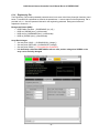
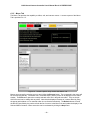
6.1
Array Control GUI
The Graphical User Interface for the Array Controller provides the capability to perform all observation
functions and to set all configuration parameters. The GUI is divided into six tabs. There are the
Observation, Setup, Engineering, Macro, System, and FITS Tabs. Each of these tabs' functionality is
described in the following sections. Some of the settings have equivalent command line commands indicated
in parentheses.
6.1.1
Common Functions
The GUI Tab includes a set of buttons for common operations. Here the buttons are listed with their
associated function and their equivalent command line command.
Figure 14
Screen Capture: Array Control GUI Common Function Buttons
GO: Starts an observation. (GO)
STOP: Gracefully stops an observation after the current exposure. (STOP)
QUIT: Exits the GUI.
ABORT: Terminates the observation immediately. Not graceful. (TODO MT: What is the command???)
CONNECT: Starts the IC software and connects the IC to its clients. (CONNECT)
There is also a command line and status window for command history and status messages as shown below.
Status Window
Figure 15
Screen Capture: Array Control GUI Command Line and Status
(TODO MT: Check all of these GUI images against Charles' new GUI stuff.)
- 37 -
NSO Infrared Camera Controller User's Manual Rev 0.13 PRERELEASE
6.1.2
Observation Tab
The Observation Tab provides the functionality listed below. Command line equivalents are listed in the
parentheses. A screen capture of the Observation Tab is provided in 6.1.2.
Observation Mode Selection:
• Selects between image capture Basic and Streaming.
o Basic: System performs one capture as specified by the configuration parameters.
Integration Time setting. ( ITIME {time} )
Pedestal Time monitoring. ( ???what’s command line equivalent to set?)
CoAddition Count setting. ( COADD {num} )
NDR Count setting. ( NDR {count} )
Cycle Count setting. ( CYCLES {count} ) Sets the number of cycles to repeat a basic
(non-streaming) read.
CoAdd Buffer selection. ( DESTBUF {bufsel} )
o Streaming: System makes continuous image captures. (TODO: There was no source image
to identify what functions are in the streaming mode tab. What are they? Cycle Count is not
relevant to Streaming Mode.)
Integration Time setting. ( ITIME {time} )
Pedestal Time monitoring. ( ???what’s command line equivalent to set?)
CoAddition Count setting. ( COADD {num} )
NDR Count setting. ( NDR {count} )
Cycle Count setting. ( CYCLES {count} )
CoAdd Buffer selection. ( DESTBUF {bufsel} )
Full Array/Subarray selection:
• Full Array: Displays the size of the full array, 1024 x 1024.
• Full Array/Subarray selection. ( ARRAYMODE {full | sub} )
• Subarray: Permits setting the size of the subarray. ( ARRAY {x} {y} {wid} {hgt} )
Autosave:
• Enable/Disable Autosave. ( AUTOSAVE {on | off} )
• Set FITS filename. ( FITSFILENAME {name} )
• Set FITS file storage path. ( SAVEPATH {path} )
• Set starting number for FITS image number. ( FITSFILENUMBER {num} )
Figure 16
Screen Capture: Array Control GUI Observation Tab
- 38 -
NSO Infrared Camera Controller User's Manual Rev 0.13 PRERELEASE
- 39 -
NSO Infrared Camera Controller User's Manual Rev 0.13 PRERELEASE
6.1.3
Setup Tab
The Setup Tab provides the functionality listed below. Command line equivalents are listed in the
parentheses. A screen capture of the Setup Tab is provided in 6.1.3.
Image
•
•
•
Monitor (DV, Data Viewer): (TODO: Verify these commands from NICI. Are there still two???)
Enable/Disable DV ( DV1ENABLE {on | off}, DV2ENABLE {on | off} )
Set Data Viewer Hostname. ( DV1HOSTNAME {hn}, DV2HOSTNAME {hn} )
Set DV Port. ( DV1PORTNUM {pn}, DV2PORTNUM {pn} )
Exposure Mode:
• Select Exposure Mode drop down box. ( ARCMODE {arc_s | arc_d} )
• Timing Gain (???explain. Is it part of exposure mode?) ( ???Command line equivalent?)
• Timing Offset (???Explain. Is it part of exposure mode?) ( ???Command line equivalent?)
Timestamping: Enable/Disable Checkbox. ( TIMESTAMPENABLE {on | off} ) (TODO: This is not a
requirement. Is it still in the GUI???)
Serial Communication: Enable/Disable Checkbox. ( SERIALENABLE {on | off} ) Enables IC Software serial
communication with the serial portserver.
- 40 -
NSO Infrared Camera Controller User's Manual Rev 0.13 PRERELEASE
6.1.4
Engineering Tab
The Engineering Tab provides password protected control over some critical Array Controller functions, listed
below. Command line equivalents are listed in the parentheses. A screen capture of the Engineering Tab is
provided in 6.1.4. See the Operator's Manual for the engineering password. Background resets are
explained in Section 4.1.1.
Background Resets (BGR):
• BGR Enable Checkbox. ( BGRENABLE {on | off} )
• BGR.ms ( BGRMS {time} ) (milliseconds)
• BGR.min.ms ( BGRMINMS {time} ) (milliseconds)
• BGR.ns ( BGRNS {time} ) (nanoseconds)
Array Bias Voltages:
• Set array bias VGGCL. ( CLKBIASVGGCL {voltage} )
• Set array bias VDETCOM. ( CLKBIASVDET {voltage} )
• Set array bias VDDUC. ( ???Command line equivalent?)
• It is absolutely critical that VDETCOM be set to a more positive voltage than VDDUC or the
array can be critically damaged.
- 41 -
NSO Infrared Camera Controller User's Manual Rev 0.13 PRERELEASE
6.1.5
Macro Tab
The Macro Tab provides the capability to define, edit, and execute macros. A screen capture of the Macro
Tab is provided in 6.1.5.
Figure 19
Screen Capture: Array Control GUI Macro Tab
Macros are executed by selecting a macro and clicking the Execute button. The commands in the macro will
be executed sequentially. Command echo, command output, and any errors will be displayed in the status
window. The Edit button opens the currently selected macro file in the gedit text editor. They are simple
ASCII files and can be editing with any editor. Note that the displayed contents of a macro edited by using
the popup gedit window or in an external editor do not refresh automatically. The Refresh button will scan
the directory specified by the path to refresh the list of macros in the Macro List and update the display of the
Selected Macro Contents. Macro execution can be terminated by clicking the Stop button.
- 42 -
NSO Infrared Camera Controller User's Manual Rev 0.13 PRERELEASE
Macros can be assigned to one of the 8 Function buttons. First select a macro from the Macro List. Next
select the number of the Function button which should be assigned by scrolling to the number next to the
m.setbutton button. Finally click the m.setbutton.
- 43 -
NSO Infrared Camera Controller User's Manual Rev 0.13 PRERELEASE
6.1.6
System Tab
The System Tab provides the functionality listed below. Generally these parameters need not be modified by
the user. Command line equivalents are listed in the parentheses. A screen capture of the System Tab is
provided in 6.1.6.
Pixel Server:
• Set the Pixel Server hostname. ( PSRVHOSTNAME {hn} )
• Set the Pixel Server port. ( PSRVPORTNUM {pn} )
Clocker:
• Set the Clocker hostname. ( CLOCKERHOSTNAME {hn} )
• Set the Clocker port. ( CLOCKERPORTNUM {pn} )
Catcher:
• Set the Catcher hostname. ( PIXELHOSTNAME {hn} )
• Set the Catcher port. ( PIXELPORTNUM {pn} )
DigiPort:
• Set the DigiPort Hostname.
• Set DigiPort Channel 1 Port. ( DIGIPORTNUM {pn1} {pn2} )
• Set DigiPort Channel 2 Port. (DIGIPORTNUM {pn1} {pn2} )
Figure 20
Screen Capture: Array Control GUI System Tab
- 44 -
NSO Infrared Camera Controller User's Manual Rev 0.13 PRERELEASE
- 45 -
NSO Infrared Camera Controller User's Manual Rev 0.13 PRERELEASE
6.1.7
FITS Header Tab
The FITS Header Tab provides control over what information is inserted into FITS file header for the
observation. The functions that can be set in the FITS Tab are listed below. The command line equivalents
are listed in parentheses. A screen capture of the FITS Header Tab is provided in 6.1.7.
FITS Header:
• Set FITS
• Set FITS
• Set FITS
• Set FITS
• Set FITS
Object Header Entry. ( FITSOBJECT {name} )
Observer Header Entry. ( FITSOBSERVER {name} )
Comment Header Entry. ( FITSCOMMENT {comment} )
Pos. Angle Header Entry. ( ???Command line equivalent?)
Plate Scale Header Entry. ( ???Command line equivalent?)
Figure 21
Screen Capture: Array Control GUI FITS Header Tab
- 46 -
NSO Infrared Camera Controller User's Manual Rev 0.13 PRERELEASE
6.2
System Setup Commands
The System Setup Commands provide for the setting of system configuration parameters like hostnames and
port numbers for various entities in the Array Controller. This section specifies the System Setup Commands.
6.2.1
PsrvHostname – Set Pixel Server Hostname
PsrvHostname - Set the hostname of the Pixel Server.
• Parameters – hn
• Range - hn: This is a text string. It must be the valid hostname of the PixelServer system.
• Initial Values - At start up, hn is "".
• Syntax - "PSRVHOSTNAME {hn}"
6.2.2
PsrvPortNum – Set Pixel Server Port Number
PsrvPortNum - Set the port number of the PixelServer.
• Parameters – pn
• Range - pn: This is a valid port number. It must be the valid port number for the server software on
the PixelServer system.
• Initial Values - At start up, hn is 2000.
• Syntax - "PSRVPORTNUM {pn}"
6.2.3
ClockerHostname – Set Clocker Hostname
ClockerHostname - Set the hostname for the system on which the Clocker software is running. Parameters
– hn.
• Parameters – hn
• Range - hn: A text string for the Clocker system’s hostname.
• Initial Values - At start up, the hn is set to "".
• Syntax - "CLOCKERHOSTNAME {hn}"
6.2.4
ClockerPortNum – Set Clocker Port Number
ClockerPortNum - Set the port number on which the Clocker is listening.
• Parameters – pn
• Range - pn: The valid port number on which the clocker is listening.
• Initial Values - At start up, the pn is set to 2000.
• Syntax - "CLOCKERPORTNUM {pn}"
6.2.5
PixelHostname – Set Pixel Software Host
PixelHostname - Set the hostname for the system on which the Catcher software is running. Parameters –
hn
TODO MT: verify that Pixel = Catcher (IPEngine2)
• Parameters – hn
• Range - hn: A text string for the Pixel system’s hostname.
• Initial Values - At start up, the hn is set to "".
• Syntax - "PIXELHOSTNAME {hn}"
6.2.6
PixelPortNum – Set Pixel Software Port Number
PixelPortNum - Set the port number on which the Catcher is listening.
TODO MT: verify that Pixel = Catcher (IPEngine2)
• Parameters – pn
- 47 -
NSO Infrared Camera Controller User's Manual Rev 0.13 PRERELEASE
•
•
•
Range - pn: The valid port number on which the clocker is listening.
Initial Values - At start up, the pn is set to 2000.
Syntax - "PIXELPORTNUM {pn}"
- 48 -
NSO Infrared Camera Controller User's Manual Rev 0.13 PRERELEASE
6.2.7
DigiHostname – Set DigiPort Hostname
DigiHostname - Set the DigiPort hostname (the DigiPort serves the remote serial channels)
• Parameters – hn
• Range - hn: A text string for the DigiPort hostname.
• Initial Values - At start up, hn is set to "".
• Syntax - "DIGIHOSTNAME {hn}"
6.2.8
DigiPortNum – Set DigiPort Port Number
DigiPortNum - Set the port numbers on which the DigiPort Serial Channels are listening.
• Parameters - pn1, pn2
• Range – pn1 and pn2
o pn1: The valid port number on which the serial channel 1 is listening
o pn2: The valid port number on which the serial channel 2 is listening
• Initial Values - At start up, the pn1 is set to 2001 and pn2 is set to 2002.
• Syntax - "DIGIPORTNUM {pn1} {pn2}"
6.3
System Commands
The System Commands set up connections from the IC Software to its clients, and starts and stops image
acquisition. This section specifies the System Commands.
6.3.1
Connect – Connect IC to Clients
Connect - Tells the IC software to start up and connect the system.
• Parameters – None.
• Range – None.
• Initial Values - At start up the IC software is running and awaiting client connections, but is not
connected to other system components (Clocker, Pixel, PixelServer, Serial Ports).
• Syntax - "CONNECT"
6.3.2
Go – Start Image Acquisition
Go - Starts the system operation and image acquisition based on current parameters.
• Parameters – None.
• Range – None.
• Initial Values – None.
• Syntax - "GO"
6.3.3
Stop – Stop Image Acquisition
Stop - Stops any image acquisition in progress. (???Graceful stop or immediate abort?)
• Parameters – None.
• Range – None.
• Initial Values – None.
• Syntax - "STOP"
- 49 -
NSO Infrared Camera Controller User's Manual Rev 0.13 PRERELEASE
6.4
General Setup and Configuration Commands
The General Setup and Configuration Commands provide the methods for setting up the Array Controller for
acquisitions. These commands prepare the Array Controller for an acquisition and should be used before the
‘Go’ command is executed. This section specifies the General Setup and Configuration Commands.
(Is there a command for the Reset to Pedestal Acquisition time??? The 'rtime' parameter is referenced in the
section on Pedestal Frames.)
6.4.1
ArcMode - Set Exposure Mode
ArcMode - Selects the type of readout scheme for the acquisition, either ARC_S or ARC_D.
• Parameters – mode
• Range - mode: ARC_S or ARC_D.
o In ARC_S (arc single) mode the system will read out only signal images.
o In ARC_D (arc double) mode the system will read out both pedestal and signal images and
will subtract off the pedestal image from the signal image to create the final image.
• Initial Values: On initial start up, ArcMode will be set to ARC_D.
• Syntax - "ARCMODE {arc_s | arc_d}"
6.4.2
Array – Set Subarray Size
Array - Set the size and location of the subarray. This subarray window determines which pixels are read out
of the detector. Note that this command is only relevant if the ArrayMode has been set to subarray.
• Parameters - x, y, wid, hgt
• Range –
o x: 0 - 448. Must be some multiple of 64 (Is this range correct???)
o y: 0 - 448. Must be some multiple of 64
o wid: >= 64. Must be multiple of 64. The sum of the wid and x must be less than 512.
o hgt: >= 64. Must be multiple of 64. The sum of the hgt and y must be less than 512.
• Initial Values:
o On initial start up, system will be in FULLARRAY mode, and will process the entire image
(1024x1024 pixels).
o On switching to SUBARRAY mode, initial values will be x = 0, y = 0, wid = 512, hgt = 512.
• Syntax - "ARRAY {x} {y} {wid} {hgt}"
6.4.3
ArrayMode – Set Array Mode (Full, Subarray)
ArrayMode - Set the system to either capture full images or to use the subarray parameters to capture subimages.
• Parameters – mode
• Range - mode: full or sub.
o If mode=full the system captures data from the entire detector.
o If mode=sub the system captures data from only the part indicated by the subarray window
parameters (set by the ‘ARRAY’ command).
• Initial Values: On initial start up, system will be in Full array mode.
• Syntax - "ARRAYMODE {full | sub}"
6.4.4
AutoSave – Set Save/Discard Data
AutoSave - Determines whether the data is saved to storage on the PixelServer or is discarded.
• Parameters – a
• Range - a: on or off.
o If a=on, data is stored on the PixelServer.
- 50 -
NSO Infrared Camera Controller User's Manual Rev 0.13 PRERELEASE
If a=off, data is discarded at the PixelServer, though system may be set to send images to
the DV.
Initial Values: On initial start up, AutoSave will be on.
Syntax - "AUTOSAVE {on | off}"
o
•
•
6.4.5
BgrEnable – Background Reset Enable
BgrEnable – Enables and disables Background Resets.
• Parameters – mode
• Range - mode: on or off.
o If mode=on the system performs BGR when the system is idle.
o If mode=off the system does not perform BGR when system is idle.
• Initial Values: On initial start up, BGR is set to on.
• Syntax - "BGRENABLE {on | off}"
This command is password protected. Disabling BGRs can damage the array and will likely lead to image
distortions. See the Operator's Manual for the engineering password command.
6.4.6
BgrMs – Set the BGR MS Parameter
BgrMs – Sets the BGR MS parameter. See Section 4.1.1 for an explanation of BGRs.
• Parameters – time
• Range - time: The BGR MS time in milliseconds.
• Initial Values: On initial start up, time is 10 milliseconds.
• Syntax - "BGRMS {time}"
This command is password protected. See the Operator's Manual for the engineering password command.
6.4.7
BgrMinMs – Set the BGR Min.MS Parameter
BgrMinMs - Sets the BGR Min.MS parameter. See Section 4.1.1 for an explanation of BGRs.
• Parameters – time
• Range - time: The BGR Min.MS time in milliseconds.
• Initial Values: On initial start up, time is 10 milliseconds.
• Syntax - "BGRMINMS {time}"
This command is password protected. See the Operator's Manual for the engineering password command.
6.4.8
BgrNs – Set the BGR NS Parameter
BgrNs - Sets the BGR NS parameter. See Section 4.1.1 for an explanation of BGRs.
• Parameters – time
• Range - time: The BGR NS time in nanoseconds.
• Initial Values: On initial start up, time is 10 nanosecs.
• Syntax - "BGRNS {time}"
This command is password protected. See the Operator's Manual for the engineering password command.
6.4.9
CamMode – Set Basic/Streaming Camera Mode
CamMode - Specifies the operation mode of the system.
• Parameters – mode
• Range - mode: Basic or Streaming.
- 51 -
NSO Infrared Camera Controller User's Manual Rev 0.13 PRERELEASE
In BASIC mode the system takes individual images. Note that individual images may be
made up of multiple samples, such as if taking multiple non-destructive reads or coadding
multiple samples into an individual image.
o In STREAMING (aka MOVIE) mode, the system continuously takes images. It continues to
do so until the ‘Stop’ command is executed.
Initial Values: On initial start up, CamMode is set to BASIC mode.
Syntax - "CAMMODE {basic | streaming}"
o
•
•
- 52 -
NSO Infrared Camera Controller User's Manual Rev 0.13 PRERELEASE
6.4.10 ClkBiasVGGCL – Set VGGCL Bias Voltage
ClkBiasVGGCL - Sets the VGGCL clock bias voltage.
• Parameters – voltage
• Range - voltage: -3.15 to -3.75 Volts
• Initial Values - On initial start up, all clock bias voltages are set to -3.75 Volts.
• Syntax - "CLKBIASVGGCL {voltage}"
This command is password protected. See the Operator's Manual for the engineering password command.
6.4.11 ClkBiasVDETL – Set VDET Bias Voltage
ClkBiasVDETL - Sets the VDET clock bias voltage.
• Parameters – voltage
• Range - voltage: -3.15 to -3.75 Volts.
• Initial Values - On in initial start up, all clock bias voltages are set to -3.75 Volts.
• Syntax - "CLKBIASVDET {voltage}"
Note that VDET is also referred to as VDETCOM. It is absolutely critical that VDETCOM be set to a more
positive voltage than VDDUC or the array can be critically damaged.
This command is password protected. See the Operator's Manual for the engineering password command.
(What’s the command for setting VDDUC???)
6.4.12 Coadd – Set Coadd Count
Coadd - Sets the system coadd count.
• Parameters - num: the number of coadds to perform to generate an image.
• Range - num: num >= 0.
o Note: An excessively high number of coadds could create an image that would exceed the 32
bit range of the integer based storage buffers.
• Initial Values - On start up, the coadd count is 1.
• Syntax - "COADD {num}"
6.4.13 Cycles – Set Cycle Count
Cycles - Sets the number of cycles in BASIC mode. This is the number of times to repeat the currently set up
procedure.
• Parameters – count
• Range - count:
o Applicable to Basic Mode image acquisitions only.
o Sets the number of times to repeat the image acquisition procedure based on the current
settings.
• Initial Values - On start up, the cycle count is 1.
• Syntax - "CYCLES {count}"
6.4.14 DoFastMode – Select Fast or Slow Clocking
DoFastMode - Select and use either the Fast or Slow clocking pattern sets.
• Parameters – mode
• Range - mode: on or off.
o If on, the system will reload the clocking patterns, using the Fast clocking pattern set to
generate images. The Fast clocking pattern set has been optimized for fast acquisition of
images within a tolerable noise range.
- 53 -
NSO Infrared Camera Controller User's Manual Rev 0.13 PRERELEASE
If off, the system will reload the clocking patterns, using the slow clocking pattern set to
generate images. The Slow clocking pattern set has been optimized for minimized noise.
Initial Values - On start up, DoFastMode is off, and is using the slow clocking pattern set.
Syntax - "DOFASTMODE {on | off}"
o
•
•
6.4.15 EPassword – Send Engineering Password
EPassword - Send the engineering password.
• Parameters – pass
• Range - pass: This is the engineering password, it's a text string. Once sent and verified, the interface
has access to engineering functionality, such as modifying BGR and Clock Bias Voltage parameters.
• Initial Value - On start up, the interface does not have access to engineering restricted functionality
• Syntax - "EPASSWORD {pass}"
See the Operator's Manual for the engineering password.
6.4.16 FitsComment – Set the FITS Comment Header
FitsComment - Sets the comment header entry for all FITS files created.
• Parameters – comment
• Range - comment: Comment is a text string.
• Initial Values - On start up, comment is "".
• Syntax - "FITSCOMMENT {comment}"
6.4.17 FitsFilename – Set FITS Filename
FitsFilename - Sets the base filename for all FITS files created and stored.
• Parameters – name
• Range - name: The name of a file can be anything, but should end with a ".fit" file type extension.
Filenames are appended with incrementing file numbers, which increment internal to the Pixel Server
system as it stores files to disk, so the resulting filename will be in the format of "somefile.XXX.fit",
with XXX being some number.
• Initial Values - On start up, the filename is "somefile.fit".
• Syntax - "FITSFILENAME {name}"
6.4.18 FitsFilenumber – Set FITS File Number
FitsFilenumber - Sets the base file number for all FITS files created and stored.
• Parameters – num
• Range - num: This is the base file number appended to the filename. Users can enter a base
filename, then set the base file number, and begin acquiring images. As each image is stored, the file
number is incremented, so images can be acquired sequentially without needing to rename each one
individually.
• Initial Value: ???What’s the initial value?
• Syntax - "FITSFILENUMBER {num}"
6.4.19 ITime – Set Integration Time
ITime - Sets the integration time. Integration time is made up of two factors, the time to clock out the pedestal
image (assuming the system is in ARC_D mode, otherwise this time is 0) and the wait time set in the
electronics.
• Parameters – time
• Range - time: time must be greater than 0 and must be greater than the Pedestal time.
• Initial Values - time is initially set to the pedestal time plus the minimum integration time.
• Syntax - "ITIME {time}"
- 54 -
NSO Infrared Camera Controller User's Manual Rev 0.13 PRERELEASE
6.4.20 NDR – Set Non-Destructive Read Count
NDR - Sets the NDR count, the number of non-destructive reads to perform per acquisition.
• Parameters – count
• Range - count: count must be greater than 0, less than 20.
• Initial Values - count is initially set to 1 at start up.
• Syntax – “NDR {count}”
- 55 -
NSO Infrared Camera Controller User's Manual Rev 0.13 PRERELEASE
6.4.21 SlowCnt – Set Slow Count
SlowCnt - Changing the slow count changes the speed at which data is clocked out of the detector. It
increases the duration of the amount of time each pattern entry is held at the detector in increments of 42ns
beyond the minimum hold time.
• Parameters – count
• Range - count: Must be between 0 and 1024.
• Initial Values - count is initially 0.
• Syntax – “SLOWCNT {count}”
6.4.22 DestBuf – Set the Image Destination Buffer
DestBuf - Sets the destination buffer to which an image is buffered.
• Parameters – bufsel
• Range - bufsel: There are 8 coadd buffers to choose from, numbered 0 to 7.
• Initial Values - At start up, buffer 0 is selected.
• Syntax - "DESTBUF {bufsel}"
6.4.23 FitsObject – Set FITS Object Header Entry
FitsObject - Set the FITS object header entry.
• Parameters – name
• Range - name: A text string. Typically this is the name or reference to the object viewed.
• Initial Values - At start up, name is "".
• Syntax - "FITSOBJECT {name}"
6.4.24 FitsObserver – Set FITS Observer Header Entry
FitsObserver - Set the FITS observer header entry.
• Parameters – name
• Range - name: A text string. Typically this is the name of the observer.
• Initial Values - At start up, name is "".
• Syntax - "FITSOBSERVER {name}"
6.4.25 RTVEnable – Enable High Speed Real Time Viewing
RTVEnable - Enable High Speed Real-Time viewing. This is accomplished by converting the image to 16 bits
and binning from 1024X1024 pixels to 256X256 pixels.
• Parameters – enable
• Range - enable: on or off.
o If enable=on real time viewing is activated, images are not saved to disk, but are binned
down to 256X256 pixels, and are sent to DV.
o If enable=off, image acquisition proceeds according to the current configuration.
• Initial Values - At start up, enable is off.
• Syntax - "RTVENABLE {on | off}"
6.4.26 SavePath – Set FITS File Path
SavePath - Sets the path to which FITS files are stored. Note, this does not create or modify any directory
structure. The save directory must already exist.
• Parameters – path
• Range - path: A text string indicating the path to which data will be stored.
• Initial Values - At start up, path is set to "/home/nso/redstar3/data".
• Syntax - "SAVEPATH {path}"
- 56 -
NSO Infrared Camera Controller User's Manual Rev 0.13 PRERELEASE
6.4.27 SerialEnable – Enable Serial Communication
SerialEnable – Enables/disables communication from the IC over Ethernet and through the remote serial
connections.
• Parameters – enable
• Range - enable: on or off.
o If enable=on the IC system will attempt to connect to the two DigiPort channels via socket
connection.
o If enable=off, the IC system will disconnect from the DigiPort channels.
• Initial Values - At start up, enable is set to off.
• Syntax - "SERIALENABLE {on | off}"
6.4.28 ReadSerial1 – Read Serial Port 1
ReadSerial1 - Read a string from serial port 1.
• Parameters – string
• Range - string: A text string.
• Initial Values - none.
• Syntax - "READSERIAL1 {string}"
6.4.29 ReadSerial2 – Read Serial Port 2
ReadSerial2 - Read a string from serial port 2.
• Parameters – string
• Range - string: A text string.
• Initial Values - none.
• Syntax - "READSERIAL2 {string}"
6.4.30 WriteSerial1 – Write to Serial Port 1
WriteSerial1 - Write a string out of serial port 1.
• Parameters – string
• Range - string: A text string.
• Initial Values - none.
• Syntax - "WRITESERIAL1 {string}"
6.4.31 WriteSerial2 – Write to Serial Port 2
WriteSerial2 - Write a string out of serial port 2.
• Parameters – string
• Range - string: A text string.
• Initial Values - none.
• Syntax - "WRITESERIAL2 {string}"
6.4.32 TimestampEnable – Enable Timestamping
TimestampEnable - Turns timestamping on and off. (Is this still supported even though it's not required???)
• Parameters – mode
• Range - mode: on or off.
o If mode=on timestamping is enabled, and system will mark the FITS header with the time of
image acquisition based on the NTP maintained time.
o If mode=off the system will mark the FITS header only with the current system time.
• Initial Values - On start up, timestamping is off.
• Syntax - "TIMESTAMPENABLE {on | off}"
- 57 -
NSO Infrared Camera Controller User's Manual Rev 0.13 PRERELEASE
6.5
Data Viewer Commands
The Data Viewer Commands provide control and configuration of the Data Viewer (also known as Image
Monitor). These commands are for configuring DV parameters in the Array Controller, not commands
handled by DV. Detailed DV usage information and commands can be found in the Data Viewer Description
addendum to this User's Manual.
6.5.1
DV1Enable – Enable Data Viewer 1
DV1Enable - Enables the sending of images to instance 1 of the DV.
• Parameters – enable
• Range - enable: on or off.
o If enable=on images are forwarded to an instance of DV. The DV1 Hostname and DV1 Port
number data are used to make the connection.
o If enable=off images are processed and stored as specified by the General Setup and
Configuration Commands.
• Initial Values - At start up, enable is off.
• Syntax - "DV1ENABLE {on | off}"
6.5.2
DV2Enable – Enable Data Viewer 2
DV2Enable - Enables the sending of images to instance 2 of the DV.
• Parameters – enable
• Range - enable: on or off
o If enable=on images are forwarded to an instance of DV. The DV2 Hostname and DV2 Port
number data are used to make the connection.
o If enable=off images are processed and stored as specified by the General Setup and
Configuration Commands.
• Initial Values - At start up, enable is off.
• Syntax - "DV2ENABLE {on | off}"
6.5.3
DV1Hostname – Set Hostname for Data Viewer 1
DV1Hostname - Sets the hostname parameter for the machine that the instance of DV indicated by DV1 is
running on.
• Parameters – hn
• Range - hn: A text string. hn is the hostname that DV is running on.
• Initial Values - At start up, hn is set to "".
• Syntax - "DV1HOSTNAME {hn}"
6.5.4
DV2Hostname – Set Hostname for Data Viewer 2
DV2Hostname - Sets the hostname parameter for the machine that the instance of DV indicated by DV2 is
running on.
• Parameters – hn
• Range - hn: A text string. hn is the hostname that DV is running on.
• Initial Values - At start up, hn is set to "".
• Syntax - "DV2HOSTNAME {hn}"
6.5.5
DV1Port – Set the Port Number for Data Viewer 1
DV1Port - Sets the port number parameter for the machine that the instance of DV indicated by DV1 is
listening on.
• Parameters – pn
• Range - pn: A valid port number, the port number on which DV1 is listening.
- 58 -
NSO Infrared Camera Controller User's Manual Rev 0.13 PRERELEASE
•
•
Initial Values - At start up, pn is set to 30123.
Syntax - "DV1PORTNUM {pn}"
- 59 -
NSO Infrared Camera Controller User's Manual Rev 0.13 PRERELEASE
6.5.6
DV2Port – Set the Port Number for Data Viewer 2
DV2Port - Sets the port number parameter for the machine that the instance of DV indicated by DV2 is
listening on.
• Parameters – pn
• Range - pn: A valid port number, the port number on which DV2 is listening.
• Initial Values - At start up, pn is set to 30123.
• Syntax - "DV2PORTNUM {pn}"
6.6
DV: Data Viewing and Arithmetic Operations
The Data Viewer DV is described in an addendum to this manual called the Data Viewer Description. DV
provides Image Monitor capability during observation and can execute arithmetic operations on buffers and
frames.
- 60 -
NSO Infrared Camera Controller User's Manual Rev 0.13 PRERELEASE
7 Setup and Operation
(TODO DT: Define software startup, system checkout, and shutdown procedures. Are there any electronics
that observers may need to power cycle?)
This section details instrument startup, checkout, shutdown, and temperature monitoring operations.
7.1
Start-up Procedure
(TODO DT)
7.2
System Checkout
(TODO DT)
7.3
Temperature Monitoring While in Use
(TODO DT)
7.4
Shutdown Procedure
(TODO DT)
- 61 -
NSO Infrared Camera Controller User's Manual Rev 0.13 PRERELEASE
8 Basic Troubleshooting
(TODO DT)
8.1
Electronics Troubleshooting
(TODO DT)
8.2
Array Troubleshooting
(TODO DT)
8.2.1
Photoemissive Defects
One defect to which arrays are susceptible is a photoemissive defect (PED). This occurs when an element
on the array emits photons.
The method to identify PEDs is by looking at a dark signal frame. If there are PEDs on the array they will
appear on the dark signal frame as bright circular regions.
8.3
Temperature Troubleshooting
(TODO DT)
8.4
Vacuum Troubleshooting
(TODO DT)
- 62 -
NSO Infrared Camera Controller User's Manual Rev 0.13 PRERELEASE
9 Acronyms and Definitions
APSS
BGR
DV
FITS
GUI
JBox
IC
MKIR
NAC
NDR
UBox
Array Power Supply Subsystem
Background Reset (Array operation)
Data Viewer, also know as Image Monitor
Flexible Image Transport System
Graphical User Interface
Mechanism Junction Box, part of the mechanism control subsystem
Instrument Control
Mauna Kea Infrared
New Array Camera
Non-Destructive Read
Mechanism Utility Box, part of the mechanism control subsystem
- 63 -
NSO Infrared Camera Controller User's Manual Rev 0.13 PRERELEASE
Appendix A: Filter Physical Specifications
(TODO DT: Update the physical specifications. These are from NICI.)
The filter wheel contains 2" square and 1" round filters. NSO may change the filters initially installed in the
filter wheel. This section provides the physical specifications of the filters.
2" Square Filter Physical Specifications
Parameter
Thickness
Width
Bevel
Value
< 5.0 mm
50.8 mm
standard
Tolerance
+/-0.25 mm
+/-0.1 mm
1" Round Filter Physical Specifications
Parameter
Thickness
Diameter
Bevel
Value
< 5.0 mm
50.8 mm
standard
Tolerance
+/-0.25 mm
+/-0.1 mm
- 64 -