1
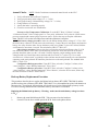
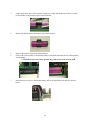
Heath Volume Corrector HVC 325 Series User’s Manual & Field Installation Guide Heath Consultants Inc. Houston, TX 713-844-1300 Fax: 713-844-1309 1-800-HEATH-US www.heathus.com 325 IS Series HVC User’s Manual & Field Installation Guide Proprietary Notice The contents of this manual are proprietary to Heath Consultants Incorporated. Reproduction of this manual, in whole or in part, is prohibited without the express written consent of Heath Consultants Incorporated. Heath Consultants Incorporated operates under a continual product improvement program and reserves the right to make improvements and/or changes without prior notification. Purpose of this Manual The HVC 325 series is a powerful device that can be assembled and programmed in a variety of configurations. The purpose of this manual is to provide information for use in instrument shop setup and field installations. Models 325 HVC IS 325 HVC HPN 77R91-1000 HPN 77R91-1000-1 HPN 77R91-1071, rev A ©COPYRIGHT 2011, Heath Consultants Incorporated 2 Table of Contents 325 IS Series ................................................................................................................................... 2 Heath Volume Corrector (HVC) Overview .................................................................................... 4 HVC Features ...............................................................................................................................4 Mounting & Installation ...................................................................................................................7 Equipment Required .....................................................................................................................7 Matching the HVC to the Meter Rotation ....................................................................................7 Meter Mounting............................................................................................................................7 Pressure Connection .....................................................................................................................8 Temperature Probe Installation ....................................................................................................8 Electrical Installation ....................................................................................................................8 Battery Pack & Back-up Batteries................................................................................................8 External Power .............................................................................................................................9 Pulse Outputs................................................................................................................................9 Form “C” PCB (Optional) ..........................................................................................................10 External Modem .........................................................................................................................10 Internal Modem ..........................................................................................................................10 Alarms ........................................................................................................................................10 HVC Host Operating Software ......................................................................................................11 Software Installation ..................................................................................................................11 Quick Start Guide Note: Click “F1” key for help on any item .....................................12 Configuration 1 Screen ...............................................................................................................13 Download and Printing Data ......................................................................................................16 Configuring for use with an IP Modem .....................................................................................17 Specifications .................................................................................................................................24 Troubleshooting .............................................................................................................................26 Annual Checks ...............................................................................................................................28 Back-up Battery Replacement Procedure ......................................................................................28 Spare Parts and Accessories...........................................................................................................31 Service Information .......................................................................................................................32 Configuration Worksheet ...............................................................................................................33 Technical Support ..........................................................................................................................36 3 Heath Volume Corrector (HVC) Overview The HVC 325 is a microprocessor based, self-contained system designed for the purpose of performing ideal gas law calculations using integral pressure, temperature and volume sensing devices. HVC Features • • • • • • • • • • • • • • • • • • • • • • • • • • • Intrinsically safe: Class I Div I Group D (without internal modem) Single Alkaline “D” battery provides power for up to 4 years Single Lithium “AA” Backup battery will provide 100% operation for up to 1 year after main battery is depleted Measures & records pressure and temperature sensors every meter revolution or every min (programmable) Continuous LCD defaults to Corrected Volume. Scrolling allows Uncorrected Volume, Pressure, Gas Temperature, Correction Factor, Main and Lithium Battery Voltage, as well as any active Alarm to be displayed. Non-volatile Flash memory saves Calibration, Transducer Coefficients Configuration & Site info if all power is lost Profiler data recording- Circular log: 130 days/hourly: Time/ Corrected/ Uncorrected/ Ave Pressure/ Ave Gas Temperature Event Log (Records alarms & configuration changes) System Alarms (H/L Press, H/L Temp, main and lithium backup battery) Contract Usage Alarms (High Day/ Warning Month/ High Month) Contract Management (Nomination/ Allocation) All alarms can be reset via scroll button (No laptop needed) Call out upon alarm Remote Communications Ready (External Direct port & Internal Remote RS232’s) Multi-Drop to several instruments from one modem (Up to 62) Previous Month Total Volumes (Uncor & Corr) can be displayed on LCD Max Day Volume “total” & Date stamp of Max Day can be displayed on LCD (Max Day can be reset via scroll button) Protocols included: Sandia (Native)/ Modbus RTU or ASCII Pulse Outputs (Uncorrected & Corrected) Units of measure (PSIA, KPA, BAR Deg. F/ Deg. C) Reliable Falling magnet/ Reed switch input Index uses all brass miter gears that are easily reversible for CW & CCW meter direction HVC Firmware can be upgraded via PC IP64, Aluminum, Powder coated paint over chromate surface prep, lockable stainless steel hasp closure (Saltwater spray tested) HVC Host software will also operate the LVC and XVC devices HVC Host software is very user friendly HVC Host is compatible with Windows 7, Win Vista and Win XP 4 Display Uncorrected mechanical index Scroll Button Earth Ground Stud Drill spot faces front of the meter Optional Transducer #2 (not yet available) ( Pressure port ( External Modem Wiring Port Locking Hasp Optional Temperature Probe Port RS232 PC Com port Universal mounting plate Figure 1: LCD Display List: Corrected Volume (default after 4 minutes)/ Uncorrected Volume/ Correction Factor/ Gas Pressure/ Gas Temp/ Main Battery Voltage/ Backup Lithium Voltage/ Active Alarms. Active Alarms will be indicated with decimal points along the bottom of the LCD and the full Display List and actual Alarms can be viewed by scrolling. 5 Primary battery Reversible gears for adapting to CW or CCW rotating meters Earth Ground Stud Back up battery (under cover) Figure 2: Inside configuration. Refer to drawing MTM-308-1 for field wiring requirements for external power and modem connections to maintain intrinsic safety. 6 Mounting & Installation Equipment Required • • • • • • Lap Top Computer (Using Win XP, Win Vista or Win 7) Communications Cable Test Gauge, Dead Weight Tester or Accurate Pressure gauge Temperature Reference (If equipped with gas temperature probe) HVC Mounting Kit (gasket, wrench) Mechanics Tool Kit Matching the HVC to the Meter Rotation The HVC 325 is equipped with a “Falling magnet/ reed switch” Mechanical Index Assembly. The HVC 325 is suitable for direct mounting on most diaphragm, rotary or mechanical turbine meters including, among others, Rockwell, Equimeter, Roots, Dresser, Romet or American with instrument drives. When directly mounted to a meter, the user should ensure that the mechanical index rotation of the HVC 325 matches the rotation of the meter. Unless otherwise specified, the HVC 325 will be shipped suitable for clockwise (CW) rotating meters. The proper rotation can be confirmed by spinning the drive dog on the bottom of the instrument in the direction required by the meter. If the mechanical counter odometer turns in the wrong direction, change rotation. When configuring the HVC 325 using HVC Host, the “UnCor Vol Input” will be configured by default to “Digital Input”. This will grey out the: “Clockwise” selection and will set the “Meter Speed” to “Fast” regardless of actual meter rotation as the falling magnet/ reed switch mechanical index is in use. If the optional Optical Index is used, the “UnCor Vol Input” will be configured to “Opto Input” which will enable the direction and speed selections. Meter Mounting The standard HVC 325 will fit most any mechanical meter instrument drive. Use gasket (provided) between the HVC 325 and meter base. Mount on to top of the meter while insuring that the HVC 325 drive pin engages properly with the meter drive. Verify meter rotation. Secure the HVC 325 with bolts (not supplied with mounting kit) to the meter base. A “Large Mounting kit” (77R61-9580) can be supplied as an option. This kit consists of mounting hardware, test plug, isolation valve, miscellaneous fittings and 1/8” tubing to allow connection of pressure to the HVC. NOTE: A rotatable base plate allows for user desired orientation of the instrument. The base plate is removed using a 5/32 hex wrench to remove four bolts. The INSTRUMENT may then be re-installed with a different orientation. The base plate MUST maintain its original position and be positioned toward the front of the meter indicated by a drill spot on the top of the base plate. CAUTION: TO PREVENT DAMAGE TO THE METER DO NOT CHANGE ORIENTATION OF THE BASE PLATE ON THE METER. ONLY CHANGE ORIENTATION OF THE INSTRUMENT. 7 Pressure Connection Connect the pressure (or gas) supply to the 1/4” NPT female connector located on the back of the HVC 325 housing. After piping is complete, check all connections to ensure that no leaks are present. Note: For ease and isolation of testing, the HVC large mounting kit is recommended. This kit will assist in future calibrations and inspection while the unit is in service. Temperature Probe Installation If equipped, the standard temperature probe (6” x 1/4” OD) should be installed into the appropriately sized thermowell filled with a thermo conductive medium such as glycol or alcohol. Insert the temperature probe into the thermowell through the standard 1/4” inch NPT male fitting (provided) until the tip of the probe reaches the bottom of the well. Secure excess armor cable length of the probe. It may be necessary to isolate the pressure and temperature connections to the pipeline, so as not to disturb the cathodic protection system. Electrical installation NOTE: Refer to drawing MTM-308-1 for field wiring requirements for external power and modem connections to maintain intrinsic safety. The HVC 325 unit must be earth grounded to maintain safe operation and warranty. The ground stud of the HVC 325 (located on the bottom left of the instrument) must be connected to a suitable known external earth ground (usually a dedicated ground rod and NOT AC ground). All of the major components in the HVC 325 are bonded together and connected internally to this ground stud. It is required that grounding be performed, especially when an external modem and/or external power supply (which requires a dedicated ground rod in close proximity to the safe area) is used. All cabling connecting to the HVC 325 must be shielded with all shields tied to case ground. For multiple device interconnections (modems, power supplies etc.) the ground stud of the HVC 325 must be tied directly to this same (safe area) ground rod rather than having a separate ground rod of its own. It may be necessary to isolate the portion of the pipe that the HVC 325 is mounted to (with insulating flanges) so as not to disturb the cathodic protection system. The American Gas Association recommends grounding all electronic field devices to a driven ground rod. This will help protect the device from transients including lightning and power surges on the pipeline. To reduce the possibility of “secondary” lightning strike damage (damage caused by static electricity fields in the immediate area), the above precautions are required. However, these precautions cannot prevent damage to an instrument that receives a “direct” lightning strike. Battery Pack and Back-up Batteries The HVC 325 units utilize (1) 1.5-volt, encapsulated “D” cell alkaline battery as its primary power source. The pack supplied with the HVC 325 consists of an alkaline dry cell and a protection circuit. 8 HVC 325 units are shipped from the factory, powered up and ready to install (Unless otherwise specified). The HVC 325 incorporates an on board uninterruptible power supply. This consists of one factory installed “AA” lithium cell (BT1) rated at 3.6 volts. This cell is easily replaced in the field. The HVC incorporates an on board battery (CR2032) for backup of the profiler log. This consists of a replaceable button style lithium battery (BT2) located on the component side of the PCB. Normal battery voltage should be displayed between the ranges of 1.5 to 1.7 volts for a new battery, and when the primary power drops below .8 volts, the unit will switch to lithium backup. Under normal conditions, the main battery pack should last up to four years and the lithium backup battery should last up to 1 year without power from the main battery. Caution: The maximum voltage allowed on the “Main battery” input is 2 volts DC. Only use the 1.5 volt battery pack supplied by Heath. If this voltage is exceeded, a protection fuse may blow and the warranty will be void. Note: If all three batteries lose power, the data that is stored in non- volatile memory will not be lost. This includes Calibration, Poly (transducer) and configuration data. Caution: To maintain the Intrinsic Safe rating, use only proper replacement batteries: main battery pack HPN 77R91-1037, Lithium backup battery, HPN 77R65-8001, and coin battery, HPN 77R65-8002. Contact Heath Consultants for replacement batteries and main battery packs. Refer to Annual Checks on page 28 for replacement procedure. External Power The HVC can be connected to an external power source (6- 15VDC). External Power is recommended when using modems which are externally powered. Pulse Outputs Form “A” (Standard) The HVC 325 is equipped to provide pulse outputs representative of uncorrected and corrected volume. There are two pulse channels available and are designated “A” and “B”. The pulse outputs are two-wire open drain. Pulser A is designated for uncorrected pulse out. Pulser B is designated for corrected pulse out. Specifications for Pulsers Pulse output electrical specification is as follows: Open drain, requires external 1 to 30 volts maximum, 25 mA maximum, and 1 K minimum load resistance. Each pulse has a standard fixed pulse width of 62.5 milliseconds with a duty cycle of 50% (62.5 ms on and 62.5 ms off). An optional 1000 milliseconds (1 sec) pulse width is also available. Because of the wide variety of applications requiring connection to the pulse output channels, consideration should be given to the site electrical classification as to the use of intrinsic safety barriers. 9 Form “C” PCB (Optional) This is an optional feature that adds two Form “A” pulses for Corrected and two for Uncorrected. External Modem The HVC 325 is equipped with two RS232 communication ports. “Com Port 1” is dedicated to local direct communication at 19200 baud using the HVC “comm cable”. “Com Port 2” is used for connecting a modem. Remote baud rates available are 300, 1200, 2400, 9600 and 19200. When configuring for a remote modem, the “Remote Modem Baud Rate” in the unit MUST match the baud rate of the field modem being used. NOTE: The “Remote Port” must have RX, TX, and GND connected (RTS is required for the “call out upon alarm” feature). NOTE: When connecting the HVC to an external modem, it is recommended to connect external power to the HVC due to higher current demand. If not, the primary alkaline battery pack’s run-time will be reduced. Internal Modem The HVC 325 may be equipped with an internal modem and phone line surge suppressor. The internal modem is a 2400-baud modem. The modem is pre-configured and pre-wired from the factory, ready for remote communication. If the HVC is equipped with the phone line suppressor, it will be connected directly into the modem’s RJ-11 connector. A 12-volt battery pack (8 “AA” batteries) is supplied, but not connected when shipped. The user must connect prior to remote communication. Assuming one twominute call per day, every day, the battery should provide approximately 2 years of service. The optional phone line surge suppressor will sacrifice itself to protect the equipment in the event of a destructive power surge on the phone line. To connect a phone line to the modem, insert the phone cable through the black wire gland on back of the case (see Figure 1). The cable must be terminated with a RJ-11 connector. Plug into surge protector if provided; otherwise, plug directly to the modem. CAUTION: The HVC must be connected to earth ground to allow the surge suppressor to operate properly. CAUTION: Internal modem option is not currently certified for use in hazardous environments. An external modem should be used when necessary. Refer to drawing MTM-308-1 for field wiring requirements on external power and modem connections to maintain intrinsic safety. Alarms All alarms can be reset manually by holding the scroll button closed for more than 4 seconds. They can also be configured and reset by using the HVC Host. An active alarm will be indicated by a lower row of dots on the LCD display. 10 HVC HOST Operating Software HVC Host is the companion software interface to the HVC instrument. The application program provides for configuration, calibration, local and remote communication, interrogation, data collection and data processing. The Auto Download feature allows automatically polling any or all the instruments (on remote communications- modems or TC/IP) from a “Master Directory” list. This “Auto Download” feature is included in the HVC Host and is supplied on CD ROM media. The self expanding executable “setup” file will guide the user through the installation process. This install will work in Windows operating systems for Win XP, Win Vista and Win 7. NOTE: This install must be on each workstation in a network. The data can be sent to a network drive and be shared by other workstations that have HVC Host installed. Remember to change the “Data Paths” of each workstation to use the same network drive and directory. DO NOT INSTALL THIS SOFTWARE DIRECTLY ONTO THE NETWORK SERVER DRIVE. Software Installation To install, locate the file “HVCHostSetup.exe”. Double-click the file to install. Follow the instructions to complete the installation process. After the software is installed, you may need to configure the com port to directly connect to the instrument. Com 1 is very common for direct communications; however, many newer computers are not equipped with a 9-pin connector for direct connect with the standard com cable. A “USB to Serial adapter” may be required. Follow the instructions included with the USB to serial adapter. After the adapter is installed and connected to the PC, go to “Start”/ Control Panel/ System/ Hardware/ Device Manager/ “Ports” (click the “+” to the left of “ports”) Look for “USB to Serial Bridge (com xx)” Enter this port number in the HVC Host (Host Setup/ Configure Host)/ “Direct”. Any port from 1-255 can be chosen. Note: Only the available ports will be listed in HVC Host/ Host setup “Name” dropdown. NOTE: HVC Host requires a screen setting of at least 800 X 600. 11 Quick Start Guide Note: Click “F1” key for help on any item. 1. Install the HVC Host software from the CD software disk provided. 2. Setup “Host Setup” (Com 1, 19200, Direct, is most common). If your com port is different than com 1 (or you are using a USB to serial adapter, find out the port number and select it). Make sure to use the same USB port every time. 3. Make any other changes to the Host Setup. Click OK. 4. Connect the communication cable from the PC to the back of the instrument. 5. Using the HVC Host software, select “Security” column/ “Logon Instrument” or select any another screen. The status bar will show “Logged on” in green. Or “Instrument Response Failed”. 6. To configure the HVC for field use, select “Configure” column/ “Configure 1”. Select appropriate configurations. (If no changes are made, the default values will be used). Click “OK” 7. To configure the site information: Go to “Configure” column/ “Configure 2” select "Configure/ Site Info". Enter the site address/ Modem baud rate (If modem is equipped) & setup pulse outputs (If pulse outputs are needed). 8. To set up the alarms: Select “Configure” column/ “Alarms and Nominations”. Select the alarm reset “Mode” (Ignore, Manual or Manual Call) and the “trip point” of the alarm. Click “OK” 9. To reset the HVC Clock to match your computer: Select “Configure” column/ Go to “Set Real Time clock”. Press the [Enter] key (Make sure the time & date is correct in the PC). 10. The default password configuration uses “logon” for full access and “readonly” for Read Only access. Since the Host setup has “logon” as the default, no passwords will be prompted and full access will be granted. To set up a “special” password for access to the HVC: Go to “Configure” column/ select “Set Access control”, change the default password for “Full Access” or “Readonly”. The “Host Setup” has a “Default Password”. If it matches the “Full Access” password, Full access is given- without needing to enter a password. This “Passive Security” is best if all instruments have the same passwords and the technicians have the same “Special” password in their computers “Host Setup”. 11. Re-Initialize the “Profiler”. This resets the recording of hourly Volumes, pressure and Gas Temp. 12. It is recommended to “Backup” the Configuration, Calibration, Transducer Coefficients & Site info. This same info can be sent to the same instrument (for example if the main pcboard was replaced) or the “Configuration” can be sent to another HVC to allow consistent configuration for each instrument. To do this: Go to “Configure” column/ select “Auto Configure”/ Backup Instrument. 13. To retrieve data or directly print a report: Select "Data", and then select the desired download or report. 12 Configure 1 Screen * Meter Drive (Input Scale Factor)= (X1, X5, X10, X100, X1,000, X10,000) Should correspond to the amount of uncorrected gas per revolution of the meter. * Uncorrected Volume Display Scale Factor= (X1, X5, X10, X100, X1,000, X10,000) Sets the scale for all Uncorrected volume displays throughout the system (LCD, Display1, Profiler etc.) * Corrected Volume Display Scale Factor= (X1, X5, X10, X100, X1,000, X10,000) Sets the scale for all Corrected volume displays throughout the system (LCD, Display1, Profiler etc.) * Uncorrected Volume= (Manual entry) Sets the reading of the Uncorrected accumulator (Usually this reading matches the mechanical index reading to ensure proper counting). * Corrected Volume= (Manual entry) Sets the reading of the Corrected accumulator (Changing this reading will not affect the hourly recording in the “Hourly Profiler”. * Uncorrected Volume/ Display 4-7 digits = Sets the amount of digits to be displayed on the LCD. Otherwise referred to as “Electronic masking” of the LCD. * Corrected Volume/ Display 4-8 digits = Sets the amount of digits to be displayed on the LCD. Otherwise referred to as “Electronic masking” of the LCD. 13 * Uncorrected Volume/ Leading blanks or Leading zeros = Sets either “Leading Blanks” or “Leading Zeros” on the LCD. * Meter Factor = (Manual entry) Applies a correction factor to the input pulse count. This can correct for a “Known and predictable” meter error. Allowable range is .95 to 1.05 (+ or – 5%). * Turbine K Factor = (Manual entry) Allows entering a K factor from an electronic turbine meter (Currently this option pcboard is not available at this time). * Turbine Divisor = Used as a divider for the “Turbine K factor” (not currently used). * Base Pressure = (Manual entry) Sets the Base Pressure used in the Correction Factor calculation. Note: Do not type “PSIG” next to the entry. * Zone Pressure = (Manual entry) Same as “Atmospheric Pressure” used in the Correction Factor calculation. Note: Do not type “PSIG” next to the entry. * Base Temp = (Manual entry) Sets the Base Temp used in the Correction Factor calculation. Note: Do not type “DegF” next to the entry. * Specific Gravity = Sets the “Specific Gravity” value of the gas for NX-19. Note: Do not type “mol %” next to the entry. * Percent Carbon Dioxide = (Manual entry) Sets the “% Carbon Dioxide” value of the gas for NX-19. Note: Do not type “mol %” next to the entry. * Wakeup Method = (Once Per Rev or Once Per Min) Sets the interval when all sensors are read and LCD is updated. “Once per rev” is most common, however, if a meter is turning faster than 1 rpm it is recommended to change to “Once per Minute” to keep the battery life within 4 years. * Meter Rotation= (Counter Clockwise, Clockwise or Heavy Duty Index). This option should only be used with optical indexes. Set to “Clockwise” or HD Index ONLY- when using “optical” input (regardless of meter rotation). Note: “Heavy Duty Index” is the same as “Clockwise”. Note 2: This value is not in use for “Falling magnet/ reed switch indexes which are standard in the HVC (It is grayed out). * Meter Speed = (Slow (15 RPM Maximum) or Fast (120 RPM Maximum)). This value is not in use for “Falling magnet/ reed switch indexes which are standard in the HVC (It is grayed out). This should only be used with optical indexes. Note: Set to “Fast” will reduce the main battery life to 3 years. Set to “Slow” or selecting “Digital” will allow up to 4 years of main battery life. * Pressure Mode = (Auto or fixed). Use “Auto” when using live pressure input. Use “Fixed” when using fixed factor measurement or there is a need to lock in a pressure reading used for pressure calculation. * Temp Mode = (Auto or fixed). Use “Auto” when using a live Gas Temp probe input. Use “Fixed” when using fixed factor measurement or there is no temperature probe connected. This fixed value will be used for the Temperature part of the calculation. 14 * FPV Mode = (Auto or fixed). Use “Auto” to calculate FPV based on the configurations of the instrument. Use “Fixed” when using fixed factor measurement or there is a need to lock in a specific FPV for calculation. * Instrument Units = (US or Metric) When configured to US units the unit will display in Cubic Feet for Volume/ PSI for Pressure/ Degrees F for temperature. When configured to Metric units the unit will display in Cubic Meters for Volume/ KPA or BAR for Pressure/ Degrees C for temperature. Caution: When setting to Metric, the values for Base Pressure, Zone Pressure, Base Temp and Transducer “Full Scale” value MUST be manually converted to reflect the desired metric unit. * Metric Pressure Units = (Bar or KPA) Select which metric unit the instrument will use for pressure. * Display Previous Month in LCD Sequence= (Check box) This setting will add the “Total accumulated Uncorrected volume” and “Total accumulated Corrected volume” from the entire previous month and display it on the LCD. The LCD reading will display [“Pc” (volume)] for Previous Corrected and [“Pu” (volume)] for Previous Uncorrected volume from the previous month. This reading will stay the same for the month until the 1st of the next month is passed, then it will be updated with the totals from the previous month. * Display Max Day in LCD Sequence= (Check box) This setting will add the “Max Corrected volume” accumulated in 24 hours and display the volume reading and the date that the max volume occurred. The LCD will display [“Hd” (volume)] push the scroll button again and the next screen will be the date that the “High day” or “Max day volume” occurred. To reset this, hold the scroll button on the “Max Day reading” for four seconds and the reading will go to zero and the date will read [- - - - - - - -] until the next Max day occurs. * Previous Monthly Accumulators= (Check box) This setting will reset the Previous Monthly Uncorrected and Corrected Accumulators back to zero. * UnCor Vol Input = (Digital or Opto Input) Set to “Digital” for the HVC standard “Falling magnet/ reed switch index. Set to “Opto Input” if using the older style “optical” index used in the older LVC/XVC instruments. Note: The HVC can use either input. 15 DOWNLOADING AND PRINTING DATA To download data follow the steps below: 1. 2. 3. 4. 5. Run the HVC Host software Go to the “Data” column. Select the report to download: “Download IOR” or “Download Profiler Report” Click “save” button to save file Click “OK” after file is saved To print Profiler data follow the steps below: 1. 2. 3. 4. 5. 6. Run the HVC Host software Go to the “Data” column. Select the report to print: “Print Daily” or “Print Monthly Report” Choose the filename of file to report Choose the time span to report on the calendars Select “Send output to”: a. Console (Creates text file and you can view the file on your screen) b. Printer (Prints report on the printer that is attached to the computer) c. File (must type a filename for a text document that will be created. Example: Monthly.doc) To print IOR (Instrument Operational Report) data follow the steps below: 1. 2. 3. 4. 5. 6. Run the HVC Host software Go to the “Data” column. Select the report to print: “Print IOR Database” Choose the filename of file to report Choose the time span to report on the calendars or choose “Last Report”. Select to “Send output to”: a. Console (Creates text file and you can view the file on your screen) b. Printer (Prints report on the printer that is attached to the computer) c. File (must type a filename for a text document that will be created. Example: IOR.doc) 16 Configuring for use with an IP modem 1. Select “Host Setup – Configure Host”. 2. Click the “Network” Port Selection and then click “OK”. 17 3. Select “Host Setup – Master Directory”. 4. Click on the “New IP Addr” button. 18 5. Enter the IP address, Port Number and choose a Name/Location for the installation. In the COM Selection drop-down box, click on “Select 4 – TCP/IP” and then click “OK”. Click “OK” back on the Master Dialing Directory window to accept the information. The screen shown below is an example using the Heath engineering HVC instrument. 6. To begin using the IP modem it must be wired correctly, configured properly and powered up. The HVC modem port baud rate must match the IP modem baud rate. Refer to the IP modem manufacturer’s users manual for further information on its use and configuration. Heath provided IP modems will be pre-configured at the factory. Select “Comm – Network – Start Session” to begin a network session. 7. 19 8. Double-click the IP modem’s site name or single click the site name and then click “OK”. Editing is also available with this screen if needed. 9. While connecting to the IP modem a status window will appear. The IP address and Port shown below are an example only. The actual values will differ. 20 10. Once connected, the Host screen will indicate the connected IP address in yellow at the bottom of the window. 11. Select “Security – Logon Instrument” to logon to the remote HVC. When successful, “Logged ON” will be indicated in green at the bottom of the window. NOTE: Please be patient while logging onto the remote HVC. It can take several seconds to logon due to network traffic and delays. 21 12. To illustrate remote IP modem communication, select “Display – Display 1 Volume Report”. 13. The Volume Report window will appear after the data has been gathered and communicated. 22 14. Remote HVC IP modem communications are available for use using the HVC Host. When finished, exit remote IP modem communications by selecting “Comm – Network – End Session”. The remote HVC will be logged off and the network session will end. 23 HVC Specifications Functionality Profiler Data Recording: Circular log; 130 days/hourly; Time/Corrected/Uncorrected/Ave Pressure/ Ave Gas Temperature Non-volatile Flash Memory: Prevents loss of calibration and configuration if all power is lost Event Log: Records alarms & configuration changes System Alarms: H/L Press, H/L Temp, Main and back-up Battery Contract Usage Alarms: High Day; Warning Month; High Month Contract Management: Nomination, Allocation Communication Protocols: Sandia (native); Modbus RTU; Modbus ASCII Units of Measure: SIG, KPA, BAR, Deg. F, Deg. C HVC Host: Win 7, Vista & Win XP; Compatible with HVC, LVC, XVC and RVC instruments Super compressibility Correction: NX-19 Mechanical Housing: Aluminum Dimensions: Overall 8.65” x 6.25” x 4.65” Weight: 6 lbs (including battery) Mounting: Universal rotatable base plate Pressure Connection: ¼” NPTF Temperature Probe: ¼” O.D. x 6” probe x 6’ armor; ¼” NPTM slip fitting Security: Stainless steel padlock hasp Coating: IP64, Aluminum, Powder coated paint over chromate surface prep Display Scroll: Push button switch Drive Mechanism: Universal drive dog, reversible mechanical Brass gear train Display: Odometer style eight digits uncorrected volume counter Electrical Primary Power Pack: 1.5 volt; 1 D cell alkaline battery with IS protection board. Back Up Power: 3.6 volt field replaceable lithium cell Transducer: 10 millivolt per volt excitation; 12 point polynomial compensation Temperature Sensor (gas and air): Integrated circuit type Flow Detector: Falling magnet/ reed input pulse Display: LCD continuous eight digits Com 1: RS-232 via serial cable Com2: RS-232 modem & multi-drop addressable via Sandia or Modbus 24 Performance Accuracy: +/- 0.5% of reading inclusive of linearity, hysteresis, repeatability, long term drift & temperature Temperature: -40°F to + 170°F Humidity: 5 – 95 % non-condensing Primary Power Pack Life: Up to 4 years based on a 1 minute wake-up interval Back-Up Power Life: Up to 1 year based on a 1 minute wake-up interval Options Outputs: Form “C” splitter (provides (2) Corrected and (2) Uncorrected pulse outs) External power: Allows connecting 6V-15VDC from external power source Communication: Internal 2400 baud “land line” modem, Multi-drop harnesses, Radio modem, Cell modem, IP Modem, surge protection. Certifications Intrinsic Safe: UL 913 and CSA C22.2, Class I, Division 1, Group D CE: EMC directive EN 61326-1 Corrosion Resistance: MIL-STD-810F 25 HVC Troubleshooting The following may serve as a quick troubleshooting guide if you encounter problems in operating the HVC: Symptom Will not log on Will not scroll Diagnosis Verify that proper com port is selected on computer. (If a Serial to USB adapter is used, find out the proper com port selection in the “Device Manager”) If error “Com not ready to send” check to see that only 1 session of HVC Host is running. After correcting problem, it may be necessary to reboot the computer. Make sure that “Default Sandia=ID” in “Host Setup” is set to 63. Check Com cable Check if pushbutton will scroll unit Check battery voltage on LCD Call factory for assistance. Call factory forvoltage assistance Check battery Test scroll switch with ohmmeter Restart instrument. Remove main power connector and then remove the lithium jumper on the PCB. Wait 5 minutes, reconnect the main power first (with good battery), then re-connect the lithium jumper (No data will be lost after restart). Call factory for assistance. Display is blank Check main & lithium battery voltage Replace all batteries Check lithium jumper (Scrape pins with a knife to clean if necessary) Restart instrument. Remove and replace batteries and reconnect. Call factory for assistance. Not responding to applied pressure Confirm pressure mode set to AUTOCheck connections of transducer wires Check connections of transducer wires Check “Full Scale” value in poly file. Calibrate column/ “Edit Calibration Terms”, enter the correct “Full Scale” Set the pressure calibration to default. -> Calibrate Column -> Edit Calibration Terms -> click the check box next to Pressure Calibration “Default”. Note: Recalibrate Pressure after these steps. Replace transducer and recalibrate Call factory for assistance 26 Symptom Not responding to temperature Diagnosis Confirm temperature mode is set to AUTO Check connections of temperature probe wires. Set the Gas temp calibration to default. -> Calibrate Column -> Edit Calibration Terms -> click the check box next to Gas Temp Calibration “Default”. Note: Recalibrate Gas Temp after these steps. Retest or replace with a different known good temperature probe. Call factory for assistance Abnormally high accumulator value(s) factors Check Uncorrected, Corrected and Meter Drive factors are proper. Make sure that the index- Magnet/ reed switch is operating properly. Call factory for assistance. Abnormally low or no accumulator value(s) Check Uncorrected, Corrected and Meter Drive factors are proper. Check instrument configuration to see if Meter rotation is proper (clockwise or counter-clockwise, optical index only). Set “Meter Speed” to “Fast” (optical index only). Check to see the index is not binding or gears are not slipping. Check wiring between index reed switch and the main board. Replace index or reed switch Call factory for assistance When calling the factory or your area representative for further troubleshooting, please have the following information ready: Customer Information 1. Name(s) 2. Company 3. Phone Number(s) 4. Location (site I.D.) Hardware Information 1. Model of Instrument 2. Instrument Firmware Version 3. Battery Voltage. 4. Instrument Serial Number 5. Date of Manufacture 6. Transducer Serial Number(s) (If Applicable) 7. Any externally connected devices 8. Phone Number (If Applicable) 9. Most Recently Printed IOR Report(If Applicable) 27 Annual Checks 1. 2. 3. 4. 5. 6. NOTE: Heath Consultants recommends annual checks on the HVC. Verify calibration and recalibrate if required. Verify proper battery main voltage (1.2 - 1.5 volts). Verify proper battery Lithium backup voltage (3.4 - 3.6 volts). Change batteries if necessary. Assure that index is operating properly. Check for corrosion at wire terminations. Pressure or Gas Temperature Calibration: Go to the HVC Host/ “Calibrate” column/ “Calibration Wizard”/ Select “Single point” or “Two point” calibration. For 2-point cal- NOW remove pressure connection & connect gauge & pressure source. Follow the steps to complete calibration. Note: The HVC will use the last read pressure until the calibration is complete. Main battery change procedure: make sure the lithium backup battery voltage is 3.5-3.6v. Pull the main battery connector off and remove the main battery. Connect the new main battery and route the battery wire away from the index. Secure the battery with o-ring. Note: To clear ANY alarm, Hold the scroll button for more than 4 seconds. The main battery HPN is 77R91-1037. Index change procedure: Remove the plate covering the main pcboard. Remove the (2) ¼-20 nuts behind the index. Lift the index out and carefully remove the wires and connector at the main pcboard. Install the index over the ¼-20 studs. Carefully align the coupler making sure the index is sitting flat and level. Install the washers and nuts and secure with 7/16” socket. Tip: Use a small screwdriver or “Allen wrench” to guide the washer and nut onto the stud. Route the wires and install the connector on the main pcboard. Re-install the plate that covers the main pcboard. The standard index HPN is 77R61-9719. Configuration Backup procedure: Using HVC Host, select the “Configure” column, select “Auto Configure”, select “Backup Instrument”, select “Save”. Configuration Restore procedure: Using HVC Host, select the “Configure” column, select “Auto Configure”, select “Restore Instrument”, select “Restore”, select the file to restore, Select only the items to restore or choose “All the above”. Back-up Battery Replacement Procedure This procedure describes how to replace the lithium back-up battery BT1 (HPN 77R65-8001) and the profiler back-up coin cell battery BT2 (HPN 77R65-8002). It is recommended to replace both batteries at the same time. If configured, the instrument will alert the user of a low lithium back-up battery on the LCD and via being connected to the instrument either by direct RS-232 or modem. Replacing the lithium back-up battery: Warning – make sure the main battery voltage is at least 1.2 Vdc! 1. 2. Remove the metal shield from the PCB. Take care not to lose the hardware. Locate BT1 in the lower middle part of the PCB. Refer to the photos below: 28 3. Lightly push down on the center retainer clip and use a small, thin bladed screwdriver to gently pry the latches on the retainer clip free from the holder. 4. Remove the lithium battery and retainer clip from the holder. 5. 6. Remove the retainer clip from the lithium battery. Observe the correct polarity of the lithium battery in the holder and insert the new lithium battery into the holder. ***WARNING: Reverse battery polarity may cause a fuse to blow on the PCB. 7. Install the retainer clip over the lithium battery and verify both latches seat properly onto the holder. 29 Replace the CR2032 coin cell back-up battery per the following: Warning – make sure the main battery voltage is at least 1.2 Vdc! 1. Locate BT2 in the lower left corner of the PCB. 2. Insert a small, thin bladed screwdriver into the gap on the left side of the battery and gently pry the left side up. 3. Remove the old battery. With the “+” of the new CR2032 coin cell battery facing up and at an angle, insert the battery under the two clips on the right hand side of the holder. 4. Push down on the new CR2032 coin cell battery until it snaps into its holder. 5. Install the metal shield back over the PCB with its hardware. Note: To clear all alarms, hold the scroll button closed for more than 4 seconds. 30 Spare Parts & Accessories Pressure Transducer The HVC may be equipped with a wide variety of ranges, most of which are available in either gauge or absolute. Temperature Probe Temperature Probes are normally supplied with six-foot l o n g metal sheathed cable. Contact factory for non-standard lengths. The temperature probe is HPN 77R91-1035. Form C Board This is for the purpose of converting the standard two-wire, normally open Form A pulse output to the three-wire Form C output or 2 Form A pulse outputs. The Form C board HPN is 77R65-9325. Modem (Internal Modem Assembly Retro Kit Part #77R61-9360) Contact the factory for other configurations. Heath industrial modems are available in one of two configurations–internal or external. The standard HVC is ready for remote RS232 communications. This will allow many different communication options: CDMA (Cellular), Radio, LAN or Satellite modems. DESCRIPTION __________________________PART# Communication Cable (6’/9pin) 325 Battery Pack Spare Internal Modem Battery Pack 325 Temp Probe (6”) Lithium Back-up Battery Telephone Surge Protector Coin Battery Standard HVC Mounting Kit (std) Large HVC Mounting Kit Form “C” Output Board Harness for Form ”C” board Index Assembly 77R61-0070 77R91-1037 77R61-9370 77R91-1035 77R65-8001 77R61-9366 77R65-8002 77R61-9220 77R61-9580 77R61-9500 77R61-9310 77R61-9719 Retro Kits Internal Modem Assembly Retro Kit) (does not include surge protector) Form C Board Retro Kit 77R61-9510 Spare PC Boards Spare 325 PCboard Spare Internal/External Modem PCboard 77R65-9320 77R65-9216 Spare Transducers 77R61-9360 Contact factory 31 Service Information: Warranties and Warranty Repair The HVC is warranted to be free from defects in material and workmanship for four (4) years from date of shipment (exclusive of the batteries). The warranty on authorized repairs in the Houston Factory Service Center (FSC) is ninety (90) days for materials and labor. This repair warranty does not extend any other applicable warranties. Our warranty covers only failures due to defects in materials or workmanship. It does not cover failure due to damage which occurs in shipment, unless due to improper packing. It does not cover failures, which result from accident, misuse, abuse, neglect, mishandling, misapplication, alteration, modification, or service other than the Houston FSC or other authorized repair center. Batteries and damage from battery leakage are excluded from this warranty. HEATH’s responsibility is expressly limited to repair or replacement of any defective part, provided the product is returned to HEATH FSC or an authorized FSC, shipped pre-paid, and adequately insured. Return shipping and insurance will be at no charge to the purchaser. HEATH does not assume liability for indirect or consequential damage or loss of any nature in connection with the use of any HEATH product. There are no other warranties expressed, implied, or written except as listed above. Obtaining Service To expedite the repair of your instrument, please follow the following procedure: 1. Contact HEATH Customer Service at 1-800-HEATH-US to obtain a Return Authorization tracking number. Repairs can be significantly delayed until authorization is obtained. a. Specify your complete shipping and billing address. b. Specify the person and contact information to be contacted for repair and shipping authorization. c. Specify the instrument product name and serial number. d. Include a brief description of the problem you are experiencing. e. Specify the person and contact information to be contacted for additional information regarding the symptoms of the failure. 2. Package and ship the HVC to the appropriate location. 3. Please specify the tracking number, product name, and serial number on all correspondence. 32 Configuration Worksheet Complete this worksheet prior to leaving the meter shop to facilitate field configuration and documentation. Always remember to download the IOR Snapshot or Configuration Log reports as a record of instrument configuration. Site Information: Site Address: Unit Serial #: Site/Meter ID: Configuration Item Value Meter Drive (Input Scale Factor): Uncorrected Volume Display Scale Factor: Leading Digits: Leading Blanks: Corrected Volume Display Scale Factor: Leading Digits: Leading Blanks: Uncorrected Volume: Corrected Volume: Base Pressure: Zone Pressure: Specific Gravity: Percent Carbon Dioxide: Percent Nitrogen: Wakeup Method: Meter Rotation: Meter Speed: Pressure Reference: 33 Configuration Item Value Pressure Mode: Temperature Mode: Fpv Mode: High Pressure Alarm Mode: Trip Point: Low Pressure Alarm Mode: Trip Point: High Temperature Alarm Mode: Trip Point: Low Temperature Alarm Mode: Trip Point: Low Battery Volt Alarm Mode: Trip Point: High Contract Month: Trip Point: Warning Contract Month: Trip Point: High Contract Day: Trip Point: Nomination: Allocation: Time Zone: Start of Day Hour: Start of Month Day: Output Pulses Y/N: Uncorrected Pulser Scale Factor: Corrected Pulser Scale Factor: Output Pulse Rate 8 per sec. or 1 per sec. : 34 Value Modem Configuration Remote Modem Baud Rate: Parity: Sandia ID: MODBUS Address : MODBUS Mode : Alarm Host Number: Modem Init String: Modem Hang Up String: 35 Technical Support 1-800-HEATHUS (1-800-432-8487) Heath Consultants Factory Service Center 9030 Monroe Road Houston, Texas 77061 Phone: (713) 844-1350 Fax: (713) 844-1398 Heath Consultants Incorporated operates under a continual product improvement program and reserves the right to make improvements and/or changes without prior notification. Heath Consultants Inc. 9030 Monroe Rd. Houston, TX. 77061 1-800-HEATHUS Fax: (713) 844-1398 www.heathus.com 36