1
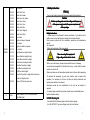
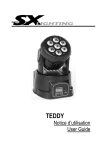
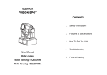
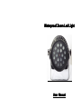
Waterproof Zoom Led Light
User Manual
Contents
Safety Instruction
VPAK Packing list
Package Content
Engineering installation and matters need attention
Installation
Cautions
The power supply and signal connection
The connection and control of the power
signal wire’s connection
6. Technical Spec
Speciifications
fications::
Voltage:AC90~240V/50~60Hz
Power consumption:210W(max)
LED: 10W LED*18pcs (RGBW-4 in 1)
Protection Rating:IP67
ZOOM-Operating range:8°~60°
Size:L308* W308* H350 MM
Weight: 11.5kg
How to Control the Package
Control Panel
Operational approach
Menu options and display function
DMX512 control
Technical Parameters
1
10
7
COLOR
MARCO
000-004
No function
005-009
010-014
015-019
020-024
Static Color Red
Static color Amber
Static color color yellow
Static Color Green
025-029
030-034
035-039
040-044
045-049
050-094
095-099
100-149
Static Color Cyan
Static Color Blue
Static Color Magenta
Static Color White
No function
Eight color step at 9 speeds
No function
Eight color fade at 5 speeds
150-154
155-166
167-178
179-190
191-202
203-214
215-226
227-238
239-250
No function
Red+Green from dark to bright
Green+Red from bright to dark
Green+Blue from dark to bright
Blue+Green from bright to dark
Blue+Red from dark to bright
Red+Blue from bright to dark
RGB from dark to bright
Blue+Red from dark to bright at the same time
green from bright to dark
Output 100% at the same time
251-255
8
0-255
Beam Zoomed: 0-100%; 0=Narrow beam,
255=Wide beam
1. Safety Instruction:
Warning
For your own safety, please read this user manual before operation.
Caution
Before operating,make sure the voltage and frequence
of the power supply match the power requirements
of the package.
Safety Instructions:
Please keep this User Manual for future consultation. If you sell the unit to
another user, be sure that they also receive this instruction booklet.
Every person involved with the installation, operation and maintenance
should:
·Be competent
·Follow the instructions of this user manual
Caution
Take care using this equipment!
High voltage risk of electric shock.
·Before your initial star-up, please make sure that there is no damage
·caused during transportation. Should there be any, consult with the dealer
and do not use the unit.
·Make sure there are not flammable materials close to the unit while operating
To maintain the equipment in good work condition and to ensure safe
operation, it is necessary for the user to follow the safety instructions and
warning notes written in the manual.
·Damages caused by user modifications to the unit are not subject to
warranty.
·For power supply connectting in series, please connect reasonable pieces
together based on safety.
2. VPAK Packing list
You should find the following items Inside the carton packing:
1pc LED-WP1018F ,1pc power Supply coble,1pc User Manual.
9
2
3. Engineering installation and matters need attention
3.1 Installation
1. Installation side
Please ensure the stability of its installation point before positioning of the
lamps in the installation, , and at least be able to withstand more than ten
times with the weight of the product structure.
2. Installation method
Using 2 units professional lights' hook, M1O bolts,make a fixed installation
through fixed nut of the light. using the insurance rope to through the handle
and the other hanging objects. Ensure it is solid when installing the lighting
and please make there is no body standing under lights or walking from it
during the installation. And check lights periodically if there are any broken
rope or hook rack is loose and so on . In addition, the power supply must be
cut off before removaling of lamps , also to ensure safety: first, to take safety
rope, and then split link, while ensuring safety of all personnel below.
3.2 Safety Precautions
1. Be sure that the local power outlet match that of the required voltage for
your unit.
2. Do not attempt to operate this unit if the power cord has been frayed or
broken. Do not attempt to remove or break off the ground prong from the
electrical cord. This prong is used to reduce the risk of electrical shock
and fire in case of an internal short.
3. Disconnect from main power before making any type of connection.
·Do not remove the cover under any conditions. There are no user
serviceable parts inside.
4. Never operate this unit when it’s cover is removed.
5. Never plug this unit in to a dimmer pack.
6. Always be sure to mount this unit in an area that will allow proper
ventilation. Allow about 6”(15cm) between this device and a wall.
7. Do not attempt to operate this unit, if it becomes damaged.
8. This unit is intended for indoor use only; use of this product outdoors
voids all warranties.
9. During long periods of non-use, disconnect the unit’s main power.
3
7:7
7 Channel Mode
dd-7
Channel
Value
Function
1
0-255
Dimmer: 0-100%
2
0-255
Red: 0-100%
3
0-255
Green: 0-100%
4
0-255
Blue: 0-100%
5
0-255
White: 0-100%
6
0-6
7-65
66-69
70-128
129-132
133-191
192-195
196-255
No fu nction
Slow to fast strobe
No function
Pulse strobe from slow to fast
No function
Strobe fading in from slow to fast
No function
Strobe fading out from slow to fast
7
0-255
Beam Zoomed: 0-100%; 0=Narrow beam, 255=Wide
beam
8:8
8 Channel Mode
dd-8
Channel
Value
Function
1
0-255
Master Dimmer
2
0-255
RED
3
0-255
GREEN
4
0-255
BLUE
5
0-255
WHITE
6
0-6
7-65
66-69
70-128
129-132
133-191
192-195
196-255
No fu nction
Slow to fast strobe
No function
Pulse strobe from slow to fast
No function
Strobe fading in from slow to fast
No function
Strobe fading out from slow to fast
8
5.3 Main Functions:
Addr
Addr: Address 001-512
SLMd
SLMd: Master/Slave/Stand-alone Mode selection
ChAn
ChAn: 3/ 4/ 5/ 6/ 7Ch Selection
ShMd
ShMd:Play/ Stob/ rGb
Pub
Pub: White Balance (R,G,B,W:0-255)
Focu
Focu:: Manual set size of beam of light
Led
Led: ON/OFF
dIS :Display-direction
tCSv
tCSv: Operating temperature
5.4 DMX512 control
4:4
4Channel Mode
dd-4
10. Always mount this unit in safe and stable matter.
11.Power-supply cords should be routed so that they are not likely to be
walked on or pinched by items placed upon or against them, paying particular
attention to the point they exit from the unit.
12. Cleaning -The fixture should be cleaned only as recommended by the
manufacturer.
13. Heat -The appliance should be situated away from heat sources such
as radiators, heat registers,stoves, or other appliances (including amplifiers)
that produce heat.
14. The fixture should be serviced by qualified service personnel when:
15. Grounded using yellow/green line
16. The ambient temperature must always be under 35°C
Channel
Value
Function
4. Power supply and signal connection
1
0-255
Red: 0-100%
2
0-255
Green: 0-100%
3
0-255
Blue: 0-100%
4
0-255
Beam Zoomed: 0-100%; 0=Narrow beam,
255=Wide beam
4.1 Set Up
Power Supply: Before plugging your unit in, be sure the source voltage in
your area matches the required voltage for your PAR Light. The PAR Light is
workable in 100-240V/50~60Hz.
Because line voltage may vary from venue to venue, you should be sure
your unit voltage matches the wall outlet voltage before attempting to operate
you fixture.
5:5
5 Channel Mode
dd-5
Channel
Value
Function
1
0-255
Dimmer: 0-100%
2
0-255
Red: 0-100%
3
0-255
Green: 0-100%
4
0-255
Blue: 0-100%
5
0-255
Beam Zoomed: 0-100%;
6:6
6 Channel Mode
dd-6
Channel
Value
Function
1
0-255
Dimmer: 0-100%
2
0-255
Red: 0-100%
3
0-255
Green: 0-100%
4
0-255
Blue: 0-100%
5
0-255
White: 0-100%
6
0-255
Beam Zoomed: 0-100%;
7
4.2 DMX Linking: To ensure proper DMX data transmission, when using
several DMX fixtures try to use the shortest cable path possible. The order in
which fixtures are connected in a DMX line does not influence the DMX
addressing. For example; a fixture assigned a DMX address of 1 may be
placed anywhere in a DMX line, at the beginning, at the end, or anywhere in
the middle. When a fixture is assigned a DMX address of 1, the DMX
controller knows to send DATA assigned to address 1 to that unit, no matter
where it is located in the DMX chain.
1. If you use a controller with 5 pins DMX output, you have to use a 5 to 3
pin adapter-cable.
2. At last unit, the DMX cable has to be terminated with a terminator.
Solder a 120 ohm 1/4W resistor between pin 2(DMX-) and pin 3(DMX+) into a
3-pin XLR-plug and plug it in the DMX-output of the last unit.
4
Display Operations
Operations:
5. Operating instructions
5.1 The following detailed function and characteristics
characteristics:
1. Display screens:Menu display and function instructions
2. Key Function :
MODE
Select program function
UP
Forward selection function or minus data
DOWN
Back choose function or add data
ENTER
Determine the selected function
5.2 Operational approach
In DMX mode,at first, set the channel mode and the start address in the
control panel , the method of it will be described later.
In slave mode, the lamp can receive DMX512 control console as the same
with the master mode, and it can identify the master signal automatically
without human intervention.
To set the lighting function, operation panel by pressing the mode button or
through the UP and DOWN key to select menu.Then enter the next menu level
or to determine the options by identifying key (ENTER). Press (MODE) key to
return to the previous menu. To change function needs to go to the bottom of
the menu, and press the OK button (ENTER) for storage.
Special attention: When the display flashes about the last of the decimal
point means that with stored function, otherwise change the data only at this
time of the boot process effective, and it will back to their original state at next
time.
5
6