1
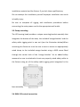
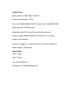
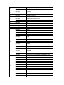
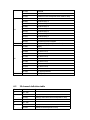
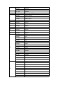
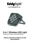
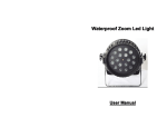
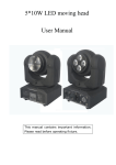
BIHEAD
LCG-BW2
USER MANUAL
KEEP THIS MANUAL FOR FUTURE NEEDS
Thank you for your patronage. We are confident that our excellent
products and service can satisfy you. For your own safety, please read
this user manual carefully before installing the device.
In order to install, operate, and maintain the lighting safety correctly. We
suggest that the installation and operation should be done by the
verified technician and follow the instruction strictly.
A
CAUTION!
Keep this device away from
rain and moisture!
CAUTION!
Unplug mains lead before opening the housing.
Every person involved with the installation, operation and maintenance
of this device has to:
-be qualified
-follow carefully the instructions of this manual
1. INTRODUCTION
Thank you for having chosen this professional moving head.
You will see you have acquired a powerful and versatile device.
Unpack the device. Inside the carton box you should find:
1. One XLR power cable
2. One user manual
3. One pcs omega
Please check carefully that there is no damage caused by transportation.
Should there be any, please consult your dealer and don’t install this
device.
2 Mounting and installation
2.1 Cautions: for added protection mount the fixtures in areas outside
walking paths, seating area, or in areas were the fixture might be
reached by unauthorized personnel.
Before mounting the fixture to any surface, make sure that the
installation area can hold a minimum point load of 10 times the device’s
weight.
Fixture installation must always be secured with a secondary safety
attachment, such as an appropriate safety cable.
Never stand directly below the device when mounting ,removing ,or
servicing the fixture, from a ceiling, or set on a flat level surface (see
illustration below).Be sure this fixture is kept at least 0.5m (1.5ft) away
from any flammable (decoration etc.)
Always use and install the supplied safety cable as a safe cable as safety
measure to prevent accidental damage and /or injury in the event the
clamp fails.
2.2 Mounting points:
Overhead mounting requires extensive experience, including amongst
others calculating working load limits, a fine knowledge of the
installation material being used, and periodic safety inspection of all
installation material and the fixture. If you lack these qualifications,
Do not attempt the installation yourself improper installation can result
in bodily injury.
Be sure to complete all rigging and installation procedures before
connecting the main power cord to the appropriate wall outlet.
2.3 Clamp mounting:
The LED moving head provides a unique mounting bracket assembly that
integrates the bottom of the base, the included ‘omega bracket’ and the
safety cable rigging point in one unit (see the illustration below).When
mounting this fixture to truss be sure to sere to secure an appropriately
rated clamp to the included omega bracket using a M10 screw fitted
through the center hole of the ‘omega bracket’. As an added safety
measure be sure to attached at least one properly rated safety cable to
the fixture using on of the safety cable rigging point integrated in the
base assembly.
2.4 DMX-512 control connection
Connect the provided XLR cable to the female 3-pin XLR output of your
controller and the other side to the male 3-pin XLR input of the moving
head. You can chain multiple Moving head together through serial
linking. The cable needed should be two core, screened cable with XLR
input and output connectors. Please refer to the diagram below.
2.4 DMX-512 connection with DMX terminator
For installations where the DMX cable has to run a long distance or is in
an electrically noisy environment, such as in a discotheque, it is
recommended to use a DMX terminator. This helps in preventing
corruption of the digital control signal by electrical noise. The DMX
terminator is simply an XLR plug with a 120 resistor connected between
pins 2 and 3, which is then plugged into the output XLR socket of the last
fixture in the chain. Please see illustrations below.
3 TECHNICAL PARAMETERS
POWER SUPPLY
Input power:AC100-240V 50/60 Hz
Power consumption :70 W
LED: 1 PCS 10W RGBW CREE LED and 4 pcs 10W RGBW LED
DMX channel:17/23channels
Movement:Pan/Tilt:X axis/ Y axis Endless rotation
Control mode:DMX512/Master-Slave/Auto run/sound
Display: LED display
8 internal program , sound mode can control by DXM 512
Beam angle:3 /25 degree
WEIGHT&SIZE
N.W: 2.5kgs
G.W: 3.5kgs
size: 32.5X25X27 cm
Packing size :54X34X29Cm (2pcs)
Product size: 160x150x240mm
4 :MENU FUNCTION
1 Addr
2 ChMd
DMX Address
DMX Mode
3 SLMd
Run Mode
4 SHMd
Internal Program
5 Soun
Sound Control
6 PAN
X Reverse
7 TIL
Y Reverse
001-512
.=CH 17
.=CH 23
.=Master
.=Slave
.=001
.=002
.=003
.=004
.=005
.=006
.=007
.=008
.=OFF
.=ON
.=OFF
.=ON
.=OFF
8 dISP
Display Reverse
9 rFAC
Reset Default
10 rST
Reset Motor
.=ON
.=OFF
.=ON
.=OFF
.=ON
5: Function Mode
5.1 DMX address setting
With this function, you can adjust the desired DMX-address via the
Control Board.
Select via the encoder.
Press the encoder; adjust the DMX address by turning the encoder.
Press the encoder to confirm.
Press the Mode/Esc-button in order return to the main menu.
Set DMX address
Display the DMX 512 value of each channel
With this function you can display the DMX 512 value of each channel.
The display automatically
Shows the channel with a value changing.
5.2 DMX Mode
The LED moving head have 17CH and 23CH
5.3 Run Mode
In the【Run】mode,you can chose【Master】mode and【Slave】mode.
5.4:Auto Play
With this function, you can run the 8 Inside program with master mode.
5.5 sound
[Music control]With this function, you can run sound-controlled.
5.6 Pan Reverse
With this function you can reverse the Pan-movement.
5.7 Tilt Reverse
With this function you can reverse the Tilt -movement.
5.8 Display Reverse
With this function you can reverse the display-movement.
5.9:Reset Default
With this function, you can select restore factory set for ON or OFF, the
default is OFF.
5.10:Reset Motor
With this function, you can reset the device via the Control Board. You
can select the different reset function by turning the encoder.
6: DMX CHANNELS
6.1
17 channel definition table
Channel
1
2
3
DMX Value
000 - 255
000-007
008-255
000 - 255
Function
X
Empty
X Motor move back and forth(Slow to fast)
Y
4
5
6
7
8
9
10
11
12
13
000-007
008-255
000-127
128-255
000-255
000-004
005-250
251-255
000-255
000-255
000-255
000-255
000-007
008-016
017-025
026-034
035-043
044-052
053-061
062-070
071-079
080-088
089-097
098-106
107-115
116-127
128-255
000-007
008-016
017-025
026-034
035-043
044-052
053-061
062-070
071-079
080-088
089-097
098-106
Empty
Y Motor Rotation(Slow to fast)
Y1 Mode
Y2 Mode
Dimmer(0-100%)
Shutter closed
Strobe effect slow to fast
Shutter open
Red
Green
Blue
White
Empty
Y1-R
Y1-G
Y1-B
Y1-W
Y1-RG
Y1-GB
Y1-BW
Y1-RW
Y1-RGB
Y1-GBW
Y1-RBW
Y1-RGW
Y1-RGBW
Y1-Macro Color Line(Slow from slow to fast)
Empty
Y2-R
Y2-G
Y2-B
Y2-W
Y2-RG
Y2-GB
Y2-BW
Y2-RW
Y2-RGB
Y2-GBW
Y2-RBW
14
15
16
17
6.2
Channel
1
2
3
4
5
107-115
116-127
128-255
000-007
008-037
038-067
068-097
098-127
128-157
158-187
188-217
218-247
248-255
000-255
000-007
008-032
033-058
059-084
085-110
111-136
137-162
163-188
189-214
215-240
241-255
250-255
Y2-RGW
Y2-RGBW
Y2-Macro Color Line(Slow from slow to fast)
Empty
LED Auto Play 1
LED Auto Play 2
LED Auto Play 3
LED Auto Play 4
LED Auto Play 5
LED Auto Play 6
LED Auto Play 7
Macro Color Line
LED Sound Control MODE
LED Auto Play Speed(Slow to Fast)
Empty
X/Y auto run 1
X/Y auto run 2
X/Y auto run 3
X/Y auto run 4
X/Y auto run 5
X/Y auto run 6
X/Y auto run 7
X/Y auto run 8
X/Y auto run 9
X/Y Sound Control
RESET(10S)
23 channel definition table
DMX Value
000 - 255
000-007
008-255
000 - 255
000 - 255
000-007
008-255
Function
X
Empty
X Motor move back and forth(Slow to fast)
X SPEED
Y
Empty
Y Motor Rotation(Slow to fast)
6
7
8
9
10
11
12
12
14
15
16
17
18
19
000-127
128-255
000 - 255
000-255
000-004
005-250
251-255
000-255
000-255
000-255
000-255
000-255
000-255
000-255
000-255
000-007
008-016
017-025
026-034
035-043
044-052
053-061
062-070
071-079
080-088
089-097
098-106
107-115
116-127
128-255
000-007
008-016
017-025
026-034
035-043
044-052
053-061
062-070
071-079
Y1 Mode
Y2 Mode
Y SPEED
Dimmer(0-100%)
Shutter closed
Strobe effect slow to fast
Shutter open
Red1
Green1
Blue1
White1
Red2
Green2
Blue2
White2
Empty
Y1-R
Y1-G
Y1-B
Y1-W
Y1-RG
Y1-GB
Y1-BW
Y1-RW
Y1-RGB
Y1-GBW
Y1-RBW
Y1-RGW
Y1-RGBW
Y1-Macro Color Line(Slow from slow to fast)
Empty
Y2-R
Y2-G
Y2-B
Y2-W
Y2-RG
Y2-GB
Y2-BW
Y2-RW
20
21
22
23
080-088
089-097
098-106
107-115
116-127
128-255
000-007
008-037
038-067
068-097
098-127
128-157
158-187
188-217
218-247
248-255
000-255
000-007
008-032
033-058
059-084
085-110
111-136
137-162
163-188
189-214
215-240
241-255
250-255
Y2-RGB
Y2-GBW
Y2-RBW
Y2-RGW
Y2-RGBW
Y2-Macro Color Line(Slow from slow to fast)
Empty
LED Auto Play 1
LED Auto Play 2
LED Auto Play 3
LED Auto Play 4
LED Auto Play 5
LED Auto Play 6
LED Auto Play 7
Macro Color Line
LED Sound Control MODE
LED Auto Play Speed(Slow to Fast)
Empty
X/Y auto run 1
X/Y auto run 2
X/Y auto run 3
X/Y auto run 4
X/Y auto run 5
X/Y auto run 6
X/Y auto run 7
X/Y auto run 8
X/Y auto run 9
X/Y Sound Control
RESET(10S)
Declaration
Cleaning and maintenance
Cleaning should be performed every 15-day period, by using a sponge which is
dipped with alcohol, rather than wet cloth or other chemical liquid, to clean the
mirror.
CAUTION
Cut off power before cleaning and maintenance!
Attention
Do not see directly light source when open the light, and make sure power off
before do any installation or maintenance.