1
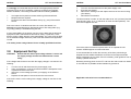
VESDA® VTT 100 User Manual Australia and Asia Vision Fire & Security Private Bag 215 495 Blackburn Road Mount Waverley, VIC, 3149 Australia Ph +61 3 9211 7200 Fax +61 3 9211 7201 Free Call 1 800 700 203 VESDA® VTT 100 User Manual VESDA Test Transformer (VTT-100) ® The Americas Vision Fire & Security 700 Longwater Drive Norwell, MA 02061, USA Ph +781 740 2223 Toll Free 800 229 4434 Fax +781 740 4433 Test Transformer Guide Europe and the Middle East Vision Fire & Security Vision House, Focus 31 Mark Road Hemel Hempstead Herts, HP2 7BW UK Ph +44 1442 242 330 Fax +441442 249 327 www.vesda.com Private and Confidential February 2004 This document may not be reproduced, in whole or in part, by any means without the prior express written permission of the copyright owner. Copyright 2003 Vision Fire & Security Pty Ltd A.C.N. 008 009 514. The manufacturer reserves the right to change designs or specifications without obligation and without further notice. VESDA, LaserTEKNIC, LaserPLUS, LaserSCANNER, LaserCOMPACT, LaserFOCUS, VESDAnet, VESDAlink, ASPIRE, AutoLearn, VSM, VConfig, InfoWORKS, PROACTIV, PRECISION and VSC are trademarks used under licence by the distributor. Part No.: 20333 Revision No. 03 VESDA® VTT 100 User Manual VESDA® VTT 100 User Manual Table of Contents 1.0 Introduction 1 2.0 Preparation and precautions 2 3.0 Equipment Set Up 3 4.0 Preparation and connection of the test wire 5 5.0 Smoke Test 6 6.0 References 6 7.0 Specification 7 8.0 Compliance 7 9.0 Ordering Information 8 VESDA® 1.0 VTT 100 User Manual VESDA® VTT 100 User Manual Introduction This Guide describes the use of the VESDA Test Transformer (VTT-100 previously known as the Hot Wire Test – Power Supply Unit (PSU)) to test very early warning aspirated smoke detection equipment. The unit provides 6VAC output from 220-240VAC or 110-120VAC mains supply. High current is passed through a test cable in order to heat it, which causes its insulation to burn giving off smoke. A timer is incorporated to provide a selectable burn period of up to 3 minutes. Note: The timer also helps to prevent the unit being inadvertently left on for an extended period. The unit must never be left on and unattended! The rocker switch on the top of the unit is the on/off switch. When power is applied and the unit is turned on the (green) “POWER” indicator on the timer flashes and power is applied to the output terminals until the set time has elapsed. Once the timer has timed out the output is switched off and the (red) “OUT” indicator on the timer illuminates. The “POWER” indicator then stops flashing and remains illuminated. The timer is reset when the switch is turned off and will run for the full selected period when the switch is turned on again. Note: The on/off switch may be illuminated while the unit is switched on. This is not an indication that the output is active. The unit must be operated for no more than three (3) minutes continuously and must be left off immediately after operating for a period of at least seven (7) minutes to allow it to cool. Note: The unit is protected against over-temperatures by a thermal switch. Once tripped, the thermal switch will not allow operation for an extended period (up to an hour) regardless of power being present or not. The thermal switch cannot be bypassed or reset manually. Part Number: VTT-10000 2.0 Preparation and precautions When performing a hot wire test ensure that local standards and regulations are understood and have been adhered to where applicable. Also, ensure that the VESDA detection equipment being proved/tested is isolated from both the local fire authority notification alerts and any suppressant actioning devices. WARNING - The hot wire test is intended to trigger a response from the Aspirating Detector under test – ensure that the consequences of this activation are understood and under control. Precautions must also be taken to ensure that all people present are aware that the test is being conducted and that those who are required to remain in the immediate vicinity of the test are suitably attired for the smoke levels about to be created. WARNING - Avoid inhaling the smoke plume as it contains small quantities of HCl. The wire burn tests, particularly the 1m and 2 x 1m tests, produce sufficiently high temperatures to generate small quantities of hydrogen chloride. However, test personnel are unlikely to be exposed to concentrations of hydrogen chloride that exceed the Occupational Exposure Standard (OES) of 5ppm in a 15 minute period unless they are directly exposed to the smoke plume. 1 2 VESDA® VTT 100 User Manual VESDA® It is strongly recommended that personnel wear appropriate protective equipment such as an E1 respirator confirming to EN140 and goggles, without ventilation, conforming to EN166 under the following situations: 1. 2. 3. • • • 4. It is impractical to perform remote switching of the transformer. Multiple tests are required. Personnel are within the immediate vicinity (e.g. 2m) of the smoke source. VTT 100 User Manual Turn the unit off and disconnect the power supply cord. Eject the fuse drawer. Remove the existing fuse and replace with one of the correct rating. (See below.) Reinsert the fuse drawer. The timer must be in mode “A” with the scale set to “min” (minutes) and the scale showing from “0” to “3” (maximum of three minutes operation). The timer should appear like this: Due to the nature of Hot Wire tests there is a minor fire hazard. It is strongly recommended that an appropriate type of fire extinguisher (e.g. CO2 or dry powder) is available during the test. It is the responsibility of the person carrying out the tests that the electrical equipment used is maintained at all times for safety. In particular, check that the supply voltage selector is set appropriately, the correct fuse is fitted for the selected voltage and that a power cord with suitable local approvals is used. If in doubt, please seek guidance from a suitably qualified electrician. 3.0 Equipment Set Up CAUTION: Ensure that the mains input voltage selector is set to suit the supply voltage and the fuse fitted has the correct rating. If the voltage selector does not match the supply voltage in use then do the following: 1. 2. 3. 4. If the timer does not match this picture then do not operate the unit. Contact VESDA support to resolve this issue. It is recommended to confirm the accuracy of the burn period using a stopwatch and a suitable multimeter connected to the output terminals before conducting any live tests. If this is necessary, seek guidance from a suitably qualified electrician. Remotely switching power to the VTT-100 from the mains outlet can assist in the reduction of possible smoke inhalation by personnel. Turn the unit off and disconnect the power supply cord. Using a screwdriver, undo the screws that hold the transparent cover in place and remove the cover. Select the correct voltage (to match your supply) on the selector switch. Replace the transparent cover and redo the cover screws. If the fuse is not the correct rating for the supply voltage in use then do the following: 3 Applicable code wire burn recommendations: 4 VESDA® • • VTT 100 User Manual BS6266:1992 recommends a burn time of 60s for one metre wire lengths and 180s for 2 metres. The NFPA 76 code also recommends the same tests with an additional test with a burn time of 60s using 2 x 1m wires connected in parallel. VESDA® 5.0 VTT 100 User Manual Smoke Test Ensure that the local fire panel is isolated from the external fire reporting equipment and that any automatic extinguishing or suppressant systems are similarly isolated. Connect power to the VTT-100 and turn the switch on. Preparation and connection of the test wire At this point, there is 6VAC applied across the test wire, the switch will illuminate and the green indicator on the timer will begin to flash. The test wire will become hot and a small quantity of smoke will be generated. The test wire samples should be carefully measured and cut to the required length. The ends should be stripped at approximately 15mm using a suitable tool. If in doubt, please seek guidance from a suitably qualified electrician. WARNING - The test wire becomes very hot during the test and will cause burns if held in the hand. Care must be taken throughout this test process. 4.0 WARNING - Only use the recommended test wire. Under no circumstances should test wires be shorter than 60cm or 2x1m in parallel. This is likely to age (or blow) the inlet fuse and may cause an unnecessary inconvenience. Ensure that no power is connected to the VTT-100. Insert the test wire between the output terminals and lay it on a supporting non-combustible platform. It is important to ensure that there are no cross overs of the wire. It may be helpful to first coil the wire using a pen or pencil as a temporary former and then lay it out. Alternatively, an arrangement to support the wire may be used with the precaution of a fire blanket positioned beneath the wire. If the equipment is in a high airflow area then it may be required to shield the wire from the airflow. WARNING - At no time is it appropriate to open the VTT-100. There are no user-serviceable parts inside. 5 Turn the unit off after the timed burn period is complete. Smoke shall be generated and the time for the detection should be recorded to ensure that transport and alarm times are within the local regulatory requirements. 6.0 References Note that appropriate guidance should be noted to the local and applicable standards and regulations such as the following: BS5389 Part1: 2002 BS6266:1992 BS6266:2002 (which cross references to the BFPSA Code of Practice) NFPA 76 :2002 BFPSA Code of Practice for Category 1 Aspirating detection systems, Appendix A. This Appendix is published on the BFPSA website at www.bfpsa.org.uk. BFPSA – British Fire Protection Systems Association. 6 VESDA® 7.0 VTT 100 User Manual Specification Type: Voltage Input: Input Rating: Fuse: Output: Operating Time: Protection: 9.0 VTT-10000 220-240VAC, 50Hz or 110-120VAC, 60Hz 800mA @ 240VAC, 50Hz, 1.6A @ 120VAC, 60Hz 220-240VAC, 800mA(T) (Anti-surge) 110-120VAC, 1.6A(T) (Anti-surge) 6VAC nominal, 20A Maximum on time: 3 minutes (180 seconds) Minimum off time between tests: 7 minutes (420 seconds) IP30 Indoor use only. This product is not to be used in the presence of moisture. 8.0 Compliance Safety: EMC: VESDA® EN 61558-1:1997 Safety of power transformers, power supply units and similar EN 61558-2-6:1997 Particular requirements for safety isolating transformers for general use EN 50081-1 EMC-Generic Emissions EN 50082-1 EMC-Generic Immunity FCC Part 15 Class A Emissions Ordering Information VESDA Part Numbers: • VTT-10000 VTT-10000-AUS VTT-10000-UK VTT-10000-EUR VTT-10000-USA • VTT 100 User Manual Australia United Kingdom Europe United States 251-001 Test Wire - 100m length. The wire has the following technical specifications: 10/0.1 mm strands insulated with PVC to a radial thickness of 0.3mm and 2 the cross sectional area of the conductor being 0.078mm . All parts can be ordered from your local VESDA distributor. Further Information Contact your nearest Vision Fire & Security office or distributor for further information. For users in the USA: This device complies with Part 15 of the FCC Rules. Operation is subject to the following two conditions: (1) this device may not cause harmful interference, and (2) this device must accept any interference received, including interference that may cause undesired operation. For users Europe, Australia and/or New Zealand: Warning - This is a class A product. In a domestic environment this product may cause radio interference in which case the user may be required to take adequate measures. 7 8