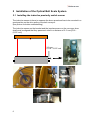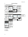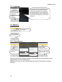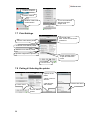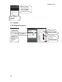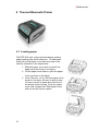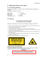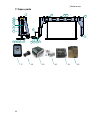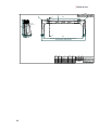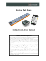
1
Optical Belt Scale
Instalation & User Manual
! Attention, important safety advice !
Do not switch on the sensor until it is completely mounted on the
machine and the laser sources are aligned to the conveyor.
The switched on sensor sends invisible laser radiation during the
measuring procedure. The sources of laser are activated only when
the conveyor is moving. This condition is indicated by the blinking red
signal lamp.
When the conveyor is not moving, the sources of laser are switched
off automatically. This state is indicated by the red signal lamp with a
short flashing signal, followed by a long pause.
However, to guarantee maximum safety, it should be always avoided
to look directly into the optical outlets while the sensor is current
supplied.
Welding current flowing through the sensor unit causes damage to
the Optical Belt Scale!
1
2
3
4
5
6
7
Content
Extent of delivery....................................................................................... 4
Installation of the Optical Belt Scale System .......................................... 6
2.1
Installing the inductive proximity switch sensor.................................... 6
2.2
Connecting the Power Supply Cable.................................................... 7
2.3
Mounting of Sensor Unit....................................................................... 7
2.4
Connecting the cables of the system ................................................. 10
Getting Started with the Mobile Phone .................................................. 11
3.1
Inserting the battery ........................................................................... 11
3.2
Powering on the Mobile Phone .......................................................... 12
3.3
Set User Interface Language ............................................................. 13
3.4
Set Date & Time................................................................................. 14
Start of SensorManager Application ...................................................... 14
4.1
Connecting to Sensor Unit ................................................................. 15
4.2
Setting Time & Date of Sensor Unit ................................................... 15
4.3
Configuration of Drum Diameter ........................................................ 16
4.4
Calibration Run .................................................................................. 16
4.5
Input Master Data............................................................................... 17
4.6
Start New Measurement .................................................................... 18
Adjusting .................................................................................................. 19
5.1
Start test measurement...................................................................... 19
5.2
Setting the span adjust....................................................................... 21
Measurements.......................................................................................... 22
6.1
Print measurements ........................................................................... 22
6.2
Print downloaded measurements....................................................... 23
6.3
Send measurements as e-mail attachment........................................ 24
6.4
View downloaded measurement as Excel spreadsheet ..................... 24
6.5
Location of exported XLS-File on the mobile phone .......................... 25
6.6
Copying the XLS-file to your desktop over USB-Cable ...................... 25
System Settings....................................................................................... 26
7.1
Admin(Login/Logout).......................................................................... 26
7.1.1
7.2
7.3
7.4
7.5
7.5.1
7.6
7.6.1
Change Login Password......................................................................... 26
Configuration...................................................................................... 26
Clock .................................................................................................. 26
Language ........................................................................................... 27
Memory .............................................................................................. 27
Clear Memory......................................................................................... 27
Units................................................................................................... 28
Setting the specific weight of a material.................................................. 28
7.7
Print-Settings ..................................................................................... 29
7.8
Pairing & Selecting the printer............................................................ 29
7.9
System ............................................................................................... 30
7.10 Diagnostic report ................................................................................ 30
8 Thermal Bluetooth Printer....................................................................... 31
8.1
Loading paper .................................................................................... 31
9 Safety Instructions Laser Class ............................................................. 32
9.1
Laser Class of Device ........................................................................ 32
9.2
Warning.............................................................................................. 32
10
Servicing and cleaning........................................................................ 32
11
Spare parts........................................................................................... 33
2
12
Connector & Cable Configurations .................................................... 35
12.1 Power supply connector on Sensor.................................................... 35
12.2 Inductive switch connector on Sensor................................................ 35
12.3 Power supply cable 2.5m ................................................................... 35
12.4 Power supply cable 15m .................................................................... 36
12.5 Inductive switch cable 2.5m ............................................................... 36
12.6 Inductive switch cable 0.5m ............................................................... 36
12.7 Inductive switch.................................................................................. 37
12.8 Data cable 3m.................................................................................... 37
13
Drawings .............................................................................................. 38
Contact:
H-Sensortechnik GmbH
Oberer Markt 3 · 4332 Au/Donau · Austria
Tel: +43 (0) 7262 54655 fax: +43 (0) 7262 54655 90
mail: [email protected] · www.h-sensortechnik.com
3
1 Extent of delivery
Sensor Unit
CAT B15Q Mobile Phone, Charger unit 110/220V, USB/charging cable, USB Charger
unit for 12V/24V
Thermal Printer + charger unit 110/220V + thermal paper
Frame & Bolts
4
Inductive sensor + Support bracket for the inductive sensor
Inductive sensor cable 0,5m + Inductive sensor cable 2,5m
A
B
Power cable 2,5m + 15m
C
D
Optional DC/DC Converter 12V/24V 10A + Cables
Technical Data
U In: 11V ... 14,5V
U Out: 24V, limited to 26V
I Out: 6A
E
5
2 Installation of the Optical Belt Scale System
2.1 Installing the inductive proximity switch sensor
The inductive sensor is there to measure the drum speed and has to be mounted in a
good position on the drive pulley of the belt conveyor.
(see picture for better understanding)
The inductive sensor on the bracket and the impulse sensor on the conveyor drum
shaft must be aligned that they pass each other in a distance of 3–5 mm [0,18 0,197 inch]
.
3-5 mm
0,118 - 0,197 inch
6
2.2 Connecting the Power Supply Cable
Connect the power supply cable (Cable D) to
the power source. The optical belt scale needs
24V DC 5 A power source.
Power supply cable D
Pin 1 / brown wire
+24V DC
Pin 2 / blue wire
-24V DC (GND)
D
2.3 Mounting of Sensor Unit
M8 hex socket head
screw
The sensor is bolted on the frame with 6 pieces M8 hex bolts which are supplied with
the unit.
Be sure to not exceed the maximum mounting height of 600mm [23,622 inch]. A
mounting position on 600 mm [23,622 inch] distance allows to measure material with
height of 400mm [15,758 inch] on the belt. If the mounting height falls below 600mm
[23,622 inch], it will narrow the full measuring range.
After powering on the sensor, two red laser dots will be visible for about 5 minutes.
Use these two dots, which are marking the active measuring line to position the
sensor accordingly the pictures.
To power on the sensor connect the power supply cable C to the sensor and to the
power supply cable D
The sensor has to be on the apex of the roller. Use the two red laser dots (one on
each side of the sensor) to check whether they match the point of contact between
belt & drum exactly!
Also be sure to pay attention to the running direction of the conveyer!
The sensor has to be mounted in the right direction!
7
Sensor over discharge drum
8
Sensor over roller station
ATTENTION:
If the red laser beams are on the side
stripper, then they have to be cut out!
The side strippers should be cut like on
the pictures!
The following table shows, which sensor fits best to each conveyor belt width
Sensor
600
800
1000
1200
1400
9
Conveyor belt width
[mm]
400 – 600
600 – 800
800 – 1000
1000 - 1300
1300 - 1600
Conveyor belt width
[inch]
15.7 – 23.6
23.6 – 31.5
31.5 – 39.4
39.4 – 51.2
51.2 - 63.0
2.4 Connecting the cables of the system
Connect the inductive sensor to the measuring sensor using the data cable A & B
The sensor is then connected to 24 V DC / 5 A power source using the power supply
cables C & D. If the sensor is used in conjunction with a 12 Volt powered system, the
DC/DC converter E has to be used. It is advised to connect the sensor to the power
supply at the ignition so that the sensor is only turned on when the ignition is on and
the plant is running.
Following please find the occupancy of the cable D:
Power supply cable D
Pin 1 / brown wire
+24V DC
Pin 2 / blue wire
-24V DC (GND)
You must take care when mounting all the cables to ensure that they can’t be
damaged or squashed when the plant is working or when the plant is being
transported i.e. the conveyors are folded.
10
3 Getting Started with the Mobile Phone
3.1 Inserting the battery
11
1. Slide the back cover latch
to the unlock position.
2. Hook your fingertip under
the back cover.
3. Pry to open the back cover.
4. You now have access to
battery compartment. Insert
the battery. Make sure the
contacts of the battery are
aligned with the connectors
in the battery compartment.
5. Make sure the rear cover is
the correct way round.
6. Engage the hooks on the
top of the back cover with
the designated holes on
your phone.
7. Push the back cover firmly
to secure it into place.
Note: Be careful not to bend
the lugs/catches/hooks on
the battery cover.
8. Press and hold the bottom
of the back cover and slide
the back cover latch to the
left to the lock the back
cover.
3.2 Powering on the Mobile Phone
To power on press the Power button.
Key functions at your fingertips:
Power button:
Press to turn on your mobile phone.
Press and hold to open the Phone options menu.
Press to lock or wake the screen when your mobile phone is
on.
Home key: Press at any time to display the Home screen. A long press of the
Home key will launch Google search or Google Now.
12
Menu key: Touch to open a menu with options that relate to the current screen
or application.
A long press of the Menu key will list the recent applications used.
A short press of the Menu key from the Home screen will display all
screen and icon settings.
Back key: Touch to display the previous screen you were working in.
Use to close onscreen keyboard.
Home screen
Booting…
3.3 Set User Interface Language
1 touch
to
display all apps
2 swipe to the
next page
3 touch
“Settings”
7 select your
Language
6 touch
“Language”
5 touch
“Language &
input”
13
4 scroll down
8 touch here
to go back
3.4 Set Date & Time
1 touch “Date &
time”
4 touch “Set date”
2 touch
“Automatic
date & time”
3 select “Off”
8 uncheck
“Automatic
time zone”
9 touch “Select time
zone”
6 touch “Set
time”
7 set time and
touch “Done”
5 set date and
touch “Done”
11 Touch the
“Home key” to
display the
home screen
12 home screen
10 select your
time zone
4 Start of SensorManager Application
3 turning Bluetooth on
1 touch
“SensorManager”
icon to start the App
2 touch “Allow” to turn
on Bluetooth
14
Bluetooth Connection
Indicator
GREEN = connected
RED = disconnected
4.1 Connecting to Sensor Unit
If Android asks for a pairing code for the Sensor then use following Bluetooth
pairing code: hsbt00000
3 select
Sensor_XXX
4 connecting to
Sensor_XXX
1 touch
“Connect
wireless”
2 touch “Scan
for devices”
unpaired devices will be
shown in “Other
Available Devices” list
Volume of current
measurement
Bluetooth Connection
Indicator
GREEN = connected
RED = disconnected
Start time of actual
measurement
4.2 Setting Time & Date of Sensor Unit
3 touch “Set
Sensor Clock”
1 touch “System
Settings”
2 touch “Clock”
5 confirm with
“OK”
6 touch “Check
Sensor Clock”
It shows the actual
time & date on
sensor unit
15
7 check if the
time & date is
actual and
confirm with
“OK”
4.3 Configuration of Drum Diameter
4 type in “0000”
as the password
1 select “admin”
2 touch “Login”
3 tap into the
password input
field to type in
6 you are logged
in if you can see
the “Change
password” button
8 adjust the
drum
diameter by
scrolling up
or down
5 confirm with
“OK”
9 touch “Apply”
10 confirm with
“OK”
7 touch
“Configuration”
11 touch the green
check to get back
into the main menu
The most accurate way to determine the roll diameter is to measure the perimeter
of the drum and acquire the diameter mathematical by dividing with Pi (3,14).
The diameter includes the rubber coating of the roll, but does NOT include the
conveyor belt.
4.4 Calibration Run
Hint: prior to the start of a new calibration run please ensure that the
SensorManager is connected to the sensor!
It has to be ensured, that the EMPTY conveyor belt is running at working speed
(sensor has to be in measuring state, red signal lamp is blinking once per second)
The conveyor belt must be clean and free from deposits of feeding material.
16
3 Calibration
has started
1 touch
“Calibration”
2 confirm with
“Yes”
When a calibration run has been started, the red signal lamp starts to flash with
fast repetition followed by a short period of steady burning signal lamp.
The calibration run is finished when the sensor enters its measuring state with the
red signal lamp blinking every second once.
4.5 Input Master Data
If customer or material name are not yet listed in the master data, the data record
has to be added.
First of all we have to choose the group in which the new data record is to be
added. (Customer or Material)
Now a description can be added to the text field by using the displayed On Screen
Keyboard.
By clicking the “Add” button, the new description is added to the list.
We can change back to the main menu by clicking the confirmation symbol in the
bottom right corner
1 touch “Input
master data”
17
2 downloading
the master
data list
3 select
“Customer” tab
4 tap into the
text input field
and the on
screen
keyboard will
be displayed
6 select “Add”
and touch the
5 type in the
custermer
name
10 type in the
material name
back key
once to close
the on screen
keyboard
9 tap into the
text input field
7 “Customer 1”
is added to the
list
12 “Material 1” is
added to the list
14 the new master
data list is sending
to the sensor unit
11 select
“Add” and
touch the
8 select
“Material” tab
15 sending is
acomplished and you
are in the main menu.
13 confirm with
“Apply”
back key
once
4.6 Start New Measurement
To start a new measurement with the new entered customer name and material
name you have to select once those and touch the “Start new measurement”
button.
1 touch “New
Measurement”
2 master
data list is
downloading
3 select the
customer
5 confirm with “Start
new measurement”
4 select the
material
6 here you can see
the configuration of
the current
measurement
7 displays the start time
& the volume of the
current measurement
Now the sensor will remember the configuration and will measure the further
measurements with this configuration till you changing it.
18
Hint: Ensure that the measured volume which is displayed on the main menu
keeps stable at zero while the empty conveyor belt is running.
If the m3 value doesn't keeps at zero then call the H-Sensortechnik service line.
5 Adjusting
For the measuring adjustment you will need a truck like on the next picture or a
container.
a
b
a
c
c
b
The capacity of the container or the truck must be at least 7m³.
Measure the distances a, b and c.
Calculate the volume of the container: V= a*b*c
5.1 Start test measurement
To ensure a good average of the test you have to measure 3 times.
Ensure that you have started a new measurement and the span adjustment factor
of the material is set to 100 % and it keeps stable at 0 m3 on a empty running belt.
(how to set the span adjust see cahpter 5.2)
Start feeding material and fill up the container (truck) till it is full.
flatten the material in the container. Make sure that the material is not compressed
during flattening.
don't compress
the filled material
flatten the material
19
After the known volume of material has run through the sensor and you have
measured 3 times, you should have 4 values at hand.
ContainerVolume = the volume of the container
Volume 1 = the value shown on SensorManager after 1st. measurement
Volume 2 = the value shown on SensorManager after 2nd measurement
Volume 3 = the value shown on SensorManager after 3rd. measurement
TotalAverage = average of the 3 measurements.
The average value is calculated using the following formula:
( Volume1 + Volume2 + Volume3)
TotalAverage [m3] =
3
The span adjust factor is calculated using the following formular:
span adjust [%] = 100 +
( ContainerVolume − TotalAverage)
(TotalAverage / 100)
Example :
ContainerVolume = 10m³
Volume1=10,34
Volume2=10,30
Volume3=10,2
SensorManagerTotalAverage [m3] =
span adjust factor [%] = 100 +
20
(10,34 + 10,30 + 10,20) 30,84
=
= 10,28m3
3
3
(10 − 10,28)
− 0,28
= 100 +
= 100 − 2,7 = 97,3 ≈ 97%
(10,28 / 100)
0,1028
5.2 Setting the span adjust
To enable the span adjust register page, connect to the sensor, go to system
settings and login as administrator. Default (factory set) password is “0000”.
3 touch „Login“
1 touch „System
settings“
5 type in the
default
password: 0000
4 tap into the
input field
2 select
„admin“ tab
6 confirm
with “OK”
8 tap into the
input field
8 type in: 4957
10 tap into
the input field
7 long click
onto the yellow
key icon
9 confirm
with “OK”
11 type in 1
to activate
15 touch “Input
master data”
15 scroll to
the left by
swiping
13 touch “Main
menu”
12 confirm
with “OK”
18 selected
material
16 select “SPAN
ADJUST” tab
17 select the
material
19 change the
value by
scrolling up or
down
21
20 touch “Apply” to
confirm the value
22 touch “Apply” to
save the changes
24 touch “New
Measurement”
23 the new
master data
are sending to
the sensor unit
21 confirm with
“OK”
29 touch “Start
new
measurement”
25 the new
master data is
downloading
from the
sensor
27 select the
customer
30 measurement
started with the
new span adjust
factor 97%
28 select the
material which
was adjusted
before
Now you can do a control measurement to check the measured volume.
If you have still difference between the measured volume and the real volume,
then you have to repeat the adjustment.
These steps must be repeated on every different material.
6 Measurements
6.1 Print measurements
1 touch “Print”
3 latest
measurement s
are downloading
4 tap on a
measuremen
t to select
2 select “Yes”
22
5 selects all
measuremen
ts on same
day
6 number of
copies to print
9 power on printer
and select “OK”
8 select “Print”
7 confirm
to show the
preview
10 connecting
to the printer
and printing
11
reconnected to
the sensor unit
11 after print
reconnecting
to the sensor
unit
6.2 Print downloaded measurements
1 touch “Print”
3 select data file
4 tap on a
measuremen
t to select
2 select “No”
8 select “Print”
7 confirm
to show the
preview
9 power on printer
and select “OK”
10 connecting
to the printer
and printing
23
6.3 Send measurements as e-mail attachment
1 touch e-mail
button
2 select data
file to send
4 select your
e-mail app to
send. Here
Gmail
5 type in
recipients email address
data file
attached to
the e-mail
3 confirm
7 Sends email & returns
to main menu
6 Touch send
icon to send
6.4 View downloaded measurement as Excel spreadsheet
1 touch XLS
button
2 select data
file to view
4 select your
office app to
view XLS-file.
Here WPS.
5 select “Just
once”
3 confirm
Measruement
spreadsheet
6 swipe here
to switch to
Date view
24
Date
spreadsheet
6.5 Location of exported XLS-File on the mobile phone
1 touch
to
display all
apps
2 select File
Manager
4 touch
“Download”
3 touch
“Phone
storage”
5 measuremen files name
format: data_Sensor_###.xls
###: number of the sensor
6.6 Copying the XLS-file to your desktop over USB-Cable
1. connect your mobile phone with the supplied usb-cable
4 double click onto
“Phone storage”
3 expand “Computer”
4 click onto “CatB15Q”
2 start “Windows Explorer”
4 double click onto
“Download”
25
4 copy the file &
paste it to your
desktop
7
System Settings
7.1 Admin(Login/Logout)
2 tap into the
input field
3 type in the
default
password: 0000
1 touch “Login”
4 confirm with
“OK”
5 you are
logged in
7.1.1 Change Login Password
2 tap into the
input field
5 type in the new
password again
for confirmation
4 confirm with
“OK”
1 touch “Change
password”
3 type in the
new password
8 the password
is changed
now
7 confirm with
“OK”
7.2 Configuration
See chapter 4.3
7.3 Clock
See chapter 4.2
26
6 confirm with
“OK”
7.4 Language
2 scroll and select your language. This
changes the UI-Language of Android
and if your language is not available in
SensorManager-App, then English will
be used in the App. The UI-Language of
Android will be displayed in the selected
language.
2 touch “Change
Language”
1 touch
“Language”
7.5 Memory
99% of the memory
are still free
1 touch “Memory”
7.5.1 Clear Memory
5 100% free
memory is shown
1 touch “Clear
Memory”
4 touch “Memory”
2 select “OK”
3 select “OK”
When the memory is cleared a backup file is stored from the data which were
downloaded on to the mobile phone.
Hint: Be sure that you have downloaded all measurements before clearing
memory!
27
7.6 Units
2 tap on to the
selection list
6 the spec. weight
of the material will
be displayed here
4 confirm
1 touch “Units”
3 select the
unit “t” as an
example
5 the unit is now “t”
7.6.1 Setting the specific weight of a material
Be sure that you are logged in!
1 touch “Input
master data”
2 scroll to the left
by swiping
3 select
“SPECIFIC
WEIGHT
4 select the
material
7 touch enter
8 touch “Apply” to
confirm
6 type in the
new value
5 tap to edit
13 touch “New
Measurement”
10 touch “Apply” to
save
9 touch “OK”
28
11 data are
sending
14 select customer
15 select material
17 now it’s measured
with the new spec.
weigth value
16 touch “Start new
measurement”
7.7 Print-Settings
Print head editor:
Max. 5 lines of text can be
printed out
Sensor name will be printed
Customer name will be printed
Material name will be printed
Specific weight will be printed
Printer selection button:
To pair and select the
printer
1 touch “Print”
7.8 Pairing & Selecting the printer
2 power on the
printer
3 touch “Scan for
devices”
4 wait till DPP250 is listed
1 touch “Print”
2 touch “Select
Printer”
29
5 select DPP-250
Hint: If a pairing
code is requested
then use following
PIN-code: 0000
for Bluetooth pairing
6 the printer is
paired and
selected
7.9 System
7.10 Diagnostic report
2 wait
SensorManag
er version
1 touch
“diagnostic
report”
30
Sensor name
Firmware version
Parameter list.
Scroll up to see
all values.
3 close with “OK”
8 Thermal Bluetooth Printer
8.1 Loading paper
The DPP-250 uses a drop-and-load design making
paper loading easy and trouble free. To load paper,
simply lift up the paper cover latch and drop in the
new roll as shown in the steps below.
1. Slide the paper cover latch to unlock the
paper cover as shown in the figure.
2. Lift the paper cover latch to open the paper
cover as shown in the figure.
3. Insert the new roll of thermal paper roll as
shown in the figure. Be sure to pull at least
12 mms or more of paper above the top of
the printer before closing. Close the paper
cover until it snaps lock. Slide paper cover
latch to lock the cover in place.
31
9 Safety Instructions Laser Class
9.1 Laser Class of Device
According to IEC 60825-1 : 2007 the sensor is classified as laser equipment of
class 3B.
Invisible laser radiation is emitted.
pulse output
pulse duration
wavelength
pulse repetition rate
Pmax = 60 mW
tpulse = 400 µs
λ = 785 nm
frep = 200 Hz
9.2 Warning
Laser radiation of class 3B is emitted
as soon as the device is working!
Therefore, the following items must be ensured before starting up the device:
•
The sensor may only be started, if it is duly attached at the sensor mounting. Otherwise
all persons concerned must wear safety goggles.
• Strip run must not be simulated.
• The optical path must be terminated in case of lack of measuring stock!
• There must not be any reflecting surfaces mounted in the optical path that might lead to
reflections! (For optical path see Fig. 5).
• During operation the operating personnel and other persons must not look directly into
the emitted beams!
• The safety instructions demanded in the standard for the use of devices of laser class
3B must be complied with.
The following warning signs must be applied at the device:
•
•
•
•
•
•
•
•
10 Servicing and cleaning
The sensor is usually service free, only from time to time lenses and windows
must be cleaned. They can be cleaned with a cotton cloth.
WARNING!
•
DO NOT USE A HIGH-PRESSURE CLEANER!
THE SENSOR IS NOT HIGH-PRESSURE PROOF!
32
11 Spare parts
1
16
15 14
2
10
12
11
3
5
6
6
8
11 11 12 13
17
33
4
8
18
7
9
4
19
20
21
22
Position Art. Nr.
1
1
1
1
1
Beschreibung
150600 Optical Belt Scale S600
150800 Optical Belt Scale S800
151000 Optical Belt Scale S1000
151200 Optical Belt Scale S1200
1
151400 Optical Belt Scale S1400
150604 Optical Belt Scale -MultiLink ML600
1
150804 Optical Belt Scale -MultiLink ML800
1
151004 Optical Belt Scale -MultiLink ML1000
1
151204 Optical Belt Scale -MultiLink ML1200
1
151404 Optical Belt Scale -MultiLink ML1400
2
151205 Frame high for 600-800mm
2
150601 Frame high for 1000-1200mm
2
151401 Frame high for 1400-1600mm
2
151203 Frame low for 600-800mm
2
151201 Frame low for 1000-1200mm
2
151206 Frame low for1400-1600m
3
110030 Power supply cable 2,5m
3
110130 Power supply cable 2,5m-MultiLink
4
110031 Power supply cable 15m
4
110132 Power supply cable 15m-MultiLink
5
110029 Inductive switch cable 2,5m
6
130007 Inductive switch cable 0,5m
7
130017 Inductive switch
8
130015 Holder for inductive switch
9
130022 Indicator for inductive switch
10
110077 Cup square neck bolt DIN603 8.8-M10x25 galvanized
11
110080 Spring washer DIN137B M10 waved, galvanized
12
110078 Hexagon nut DIN982 Kl.8 M10 galvanized
13
110076 Hexagon head screw DIN933 8.8-M10x35 galvanized
14
110079 Spring washer DIN137A M8 galvanized
15
110075 Hexagon socket head cap screw DIN912 -M8x20 galvanized
16
110143 Large diameter washer 8,4x30x1,5 A2, stainless
17
140000 Mobile Handheld
18
140007 Car-USB-Charger for Handheld 12V und 24V
19
140001 Bluetooth thermo printer
20
120008 Paper roll for printer
21
130019 DC/DC converter 12V -> 24V
22
130020 AC/DC converter 230V -> 24V
23
110081 User manual
Contact:
H-Sensortechnik GmbH
Oberer Markt 3 · A – 4332 Au/Donau
Tel: +43 (0) 7262 54655-0 DW Fax 90
mail: [email protected] · www.h-sensortechnik.com
34
12 Connector & Cable Configurations
12.1 Power supply connector on Sensor
Pin
#
1
2
L
4
5
N
7
Signal
Signal
direction
Power supply 0 VDC
(GND)
Power supply +24 VDC
Not connected
RS-422 / Bluetooth mode
selector
RS-422 sensor out RS-422 sensor out +
RS-422 sensor in +
RS-422 sensor in -
GND
input
n.c.
input
diffrential output
diffrential output
diffrential input
diffrential input
Signal Info
GND internal connected to housing
via reverse battery protection diode
+24VDC +- 20%, Imax = 3,5A
n.c.
“high” +24 VDC = RS-422 mode
“low” 0V = Bluetooth mode
Use only in RS-422 mode
Use only in RS-422 mode
Use only in RS-422 mode
Use only in RS-422 mode
12.2 Inductive switch connector on Sensor
Pin #
Signal
Signal direction
Signal Info
L
N
+12 VDC
Signal
0 VDC
out
in
out
Power supply inductive switch
Signal receive from inductive switch
Power supply inductive switch
12.3 Power supply cable 2.5m
Pin #
1
2
L
4
5
35
Signal
Lead color
0 VDC (GND)
+24 VDC
Not connected
Not connected
Not connected
blue
brown
Pin #
2
1
PE
N
7
Not connected
Not connected
Not connected
12.4 Power supply cable 15m
Pin #
1
2
PE
Signal
Lead color
+24 VDC
0 VDC (GND)
Not connected
brown
blue
12.5 Inductive switch cable 2.5m
Pin #
Signal
Lead color
L
+12 VDC
0 VDC
Brown
White
N
Signal
Not connected
Yellow
Pin #
1
2
3
PE
12.6 Inductive switch cable 0.5m
Pin #
1
2
3
PE
36
Signal
Lead color
+12 VDC
0 VDC
Signal
Not connected
Brown
Blue
Black
Pin #
1
2
4
3
12.7 Inductive switch
Pin #
1
2
3
4
Signal
+12 VDC
0 VDC
Not connected
Signal
12.8 Data cable 3m
Pin # Signal
Signal
direction
Signal Info
Lead
color
1
Power supply 0 VDC
(GND)
GND
Grown
& white
2
L
4
input
n.c.
Input
5
Power supply +24 VDC
Not connected
RS-422 / Bluetooth mode
selector
RS-422 sensor out -
GND internal connected to
housing via reverse battery
protection diode
+24VDC +- 20%, Imax = 3,5A
n.c.
“high” +24 VDC = RS-422 mode
“low” 0V = Bluetooth mode
Use only in RS-422 mode
N
RS-422 sensor out +
Use only in RS-422 mode
pink
7
RS-422 sensor in +
Use only in RS-422 mode
Green
Use only in RS-422 mode
yellow
RS-422 sensor in -
37
Diffrential
output
Diffrential
output
Diffrential
input
Diffrential
input
red
n.c.
blue
gray
13 Drawings
Passung
TOLERANCE
Abmasse
Passung
DEVIATIONS TOLERANCE
Abmasse
Aenderung
DEVIATIONSREVISION
Mitteilung Nr.
NOTICE NO.
Datum
DATE
Name
NAME
Bemerkung
REMARK
Abweichungen fuer Masse ohne Toleranzangaben nach
Werkstoff (Fertigabmessungen), Rohteil-Nr., Modell-Nr., Gesenk-Nr.
DIN 7168 mittel
MATERIAL (FINAL DIMENSIONS), BLANK NO., PATTERN NO., DIE NO.
DEVIATIONS FOR DIMENSIONS WITHOUT INDICATION OF
TOLERANCES ACCORDING TO DIN 7168 MEDIUM
Massstab
SCALE
1:2
Gezeichnet
DRAWN
M. Kurt
Geprueft
CHECKED
Gewicht
WEIGHT
Fuer diese Zeichnungen behalten wir uns alle Rechte vor
ALL RICHTS RESERVED
3,950 kg
Datum
Benennung
DATE 13.09.2006TITLE
Datum
DATE
Sensor S600
13.09.2006
Zeichnungsnummer
DRAWING NO.
Format
SIZE
H-Sensortechnik G.m.b.H.
PEM-Straße 2, 4310 Mauthausen
Tel.: +43 (0) 7238 / 29 424
Fax: +43 (0) 7238 / 29 424 90 Ersatz fuer
SUBSTITUTE FOR
Passung
TOLERANCE
Abmasse
DEVIATIONS
Passung
TOLERANCE
Mitteilung Nr.
NOTICENO.
Abmasse
DEVIATIONS
Abweichungen fuer Masse ohne Toleranzangaben nach
DIN7168 mittel
DEVIATIONSFORDIMENSIONSWITHOUTINDICATIONOF
TOLERANCESACCORDINGTODIN7168 MEDIUM
Massstab
SCALE
Gezeichnet
DRAWN
Geprueft
CHECKED
1: 2
M.Kurt
Datum
DATE
Datum
DATE
Aenderung
REVISION
Blatt
von
SHEET OF
1
1
Ersetzt durch REPLACED BY
Datum
DATE
Name
NAME
Bemerkung
REMARK
Werkstoff (Fertigabmessungen), Rohteil-Nr., Modell-Nr., Gesenk-Nr.
MATERIAL(FINALDIMENSIONS), BLANKNO., PATTERNNO., DIENO.
13.09.2006
Gewicht
WEIGHT
Benennung
TITLE
3,950 kg
Fuer diese Zeichnungen behalten wir uns alle Rechte vor
ALLRICHTSRESERVED
Sensor S800
13.09.2006
Zeichnungsnummer
DRAWINGNO.
H-Sensortechnik G.m.b.H.
PEM-Straße 2, 4310 Mauthausen
Tel.: +43 (0) 7238 / 29 424
Fax:+43(0) 7238 / 29 424 90
38
Aenderung
REVISION
A2
H-101.160
H-101.180
Ersatz fuer
SUBSTITUTEFOR
Format
SIZE
Aenderung
REVISION
A2
Ersetzt durch REPLACEDBY
Blatt
SHEET
1
von
OF
1
Passung
TOLERANCE
Abmasse
DEVIATIONS
Passung
TOLERANCE
Abmasse
DEVIATIONS
Abweichungen fuer MasseohneToleranzangabennach
ISO-2768-f
DEVIATIONSFORDIMENSIONSWITHOUTINDICATIONOF
TOLERANCESACCORDINGTOISO-2768-f
Massstab
SCALE
Gezeichnet
DRAWN
Geprueft
CHECKED
Aenderung
REVISION
MitteilungNr.
NOTICENO.
Datum
DATE
Bemerkung
REMARK
Name
NAME
Werkstoff (Fertigabmessungen), Rohteil-Nr., Modell-Nr., Gesenk-Nr.
MATERIAL(FINALDIMENSIONS), BLANKNO., PATTERNNO., DIENO.
1: 1
Alu
Fuer dieseZeichnungen behalten wir uns alle Rechtevor
ALLRICHTSRESERVED
Gewicht
WEIGHT
Benennung
TITLE
Datum
DATE
Datum
DATE
Zeichnungsnummer
DRAWINGNO.
H-Sensortechnik GmbH
PEM-Straße 2, 4310 Mauthausen
Tel.: +43(0) 7238 / 29 424
Fax: +43(0) 7238 / 29 424 90
Ersatz fuer SUBSTITUTEFOR
Format
SIZE
Aenderung
REVISION
Blatt
SHEET
von
OF
H-100.110
M8
Ersetzt durch REPLACEDBY
SEPARATESTÜCKLISTE:
LIST OFPARTS:
Passung
TOLERANCE
Abmasse
DEVIATIONS
H-900.120
H-900.120
Passung
TOLERANCE
ISO2768-m
Abmasse
DEVIATIONS
Abweichungenfuer MasseohneToleranzangabennach
DIN7168 mittel
DEVIATIONSFORDIMENSIONSWITHOUTINDICATIONOF
TOLERANCESACCORDINGTODIN7168 MEDIUM
Massstab
SCALE
Gezeichnet
DRAWN
Geprueft
CHECKED
1: 2
M.Kurt
Datum
DATE
Datum
DATE
Aenderung
REVISION
MitteilungNr.
NOTICENO.
13.09.2006
3,950 kg
Name
NAME
Bemerkung
REMARK
Fuer diese Zeichnungenbehaltenwir unsalleRechtevor
ALLRICHTSRESERVED
Sensor S1200
13.09.2006
Zeichnungsnummer
DRAWINGNO.
Hartl Sensortechnik G.m.b.H.
PEM-Straße2, 4310Mauthausen
Tel.: +43(0) 7238 / 29 350
Fax: +43(0)7238 / 2935040
39
Datum
DATE
Werkstoff (Fertigabmessungen), Rohteil-Nr., Modell-Nr., Gesenk-Nr.
MATERIAL(FINALDIMENSIONS), BLANKNO., PATTERNNO., DIENO.
Gewicht
WEIGHT
Benennung
TITLE
H-100.220
Ersatz fuer
SUBSTITUTEFOR
Format
SIZE
Aenderung
REVISION
A1
Ersetzt durch REPLACEDBY
Blatt
SHEET
1
von
OF
1
REV
REVISIONHISTORY
DESCRIPTION
DATE
APPROVED
1
2
A
3
1250
490
595
Richtlaser
Red-Laser pointer
60
89
190
305
Schnitt A-A
34
64
64
A
1526
1654 =max.Breite, verstellbar, bei Montage anpassen, gegebenfalls Mittelteil kürzen
=max. width, adjustable, if necessary cut as needed
ItemNumber
Document
Number
1*
H-900.100
2
H-900.200
3
4*
40
H-900.050
Title
Material
Rahmen-Mittelteil
Stahl, Bau-
Seitenteil-Links
Stahl, Bau-
Quantity
1
1
Seitenteil-Rechts
1
Kabelschutz
1
NAME
DATE
DRAWN
kurt
10/20/08
CHECKED
ENGAPPR
MGRAPPR
UNLESSOTHERWISESPECIFIED
DIMENSIONSAREINMILLIMETERS
ANGLES±X.X°
2 PL±X.XX3 PL±X.XXX
TITLE
Rahmen 800-1200 / Frame 800-1200
SIZE DWGNO
A2
H-900.200
FILENAME: H-900.200 Rahmen_2.dft
SCALE:
WEIGHT:
SHEET1OF1
REV