1
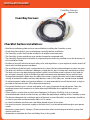
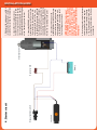
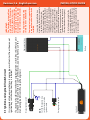
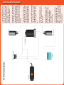
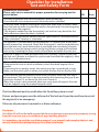
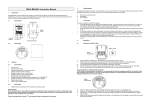
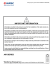
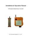
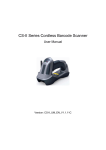
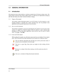
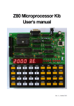
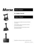
GENERAL INSTALLATION GUIDE
Revision 2.6 - English version
INSTALLATION GUIDE
CoastKey harness
connector
CoastKey harness
Checklist before installation:
• Read the installation guide and user manual before installing the CoastKey system.
• Check that the engine(s) starts and operates normally before installation.
• The CoastKey system shall not be installed in an explosive environment.
• The CoastKey system and design may not be changed or tampered with.
• The CoastKey should only be used for its original purpose and only installed as per the directions in
this Installation Guide.
• Familiarise yourself with the national safety rules and regulations in your region to avoid a breach of
these rules and help prevent accidents.
• The installation of the lock unit is permitted only in areas that are protected against water intrusion.
• The lock unit shall be installed on a fiberglass, wood, plastic, glass or other non-conductive surface.
The lock unit must not be attached to carbon, cables, wire or other metal surfaces as this leads to
loss of signal strength, which will affect the radio communication between the key and lock unit.
Strong electromagnetic fields may also affect the system. Locating the lock unit in the immediate
vicinity of conductive cables and any radio devices such as VHF, radar, etc. should also be avoided.
• To achieve optimal radio and signal conditions, it is recommended to install the lock unit as high as
possible in the boat (at least 70 cm above the waterline).
• Ensure that the lock unit is secure and stable, so it is easy to operate the push button. Clean the
attachment point with acetone or a similar cleaning fluid before the supplied Velcro strip is
attached.
• Other wireless systems that use the same frequency (In Europe: 433 MHz), such as a remote
controlled anchor winch or bow thruster, can affect the operational stability of the CoastKey system.
• The distance between the installation point of the lock unit and the pilot’s usual position should be
as short as possible and not exceed a radius of 1.5 meters.
• In a dual installation the lock units should be placed at least 30 cm apart.
• For security reasons, the power supply to the lock unit(s) is to be connected through a main power
switch.
• Maximum system load is 10 amps. (Check current draw when connecting to external systems like
anchor winch etc.)
• Remember to complete the Test and Safety Form in this guide.
Revision 2.6 - English version
INSTALLATION GUIDE
Installation procedure:
1. General
Make sure the battery terminals, the main power switch and all common connection points are free of corrosion and that there are no loose connections. Check
that the engine(s), tilt and any other devices that CoastKey will be connected to,
are functioning normally before starting the installation. The main switch must be
switched off during the installation.
2. Installation Procedure
All of the connections are made from the point of view that the CoastKey lock unit
should work in parallel to the manual ignition switch. To illustrate this in the best
possible way, all of the electrical wiring diagrams will show both the manual ignition switch and the CoastKey lock unit.
All electrical connections must be connected with waterproof solder sleeves
or similar.
Make sure that all of the connections are performed correctly in terms of reliability
and according to best practice for marine electronics. Check carefully that any
crimp sleeves are correctly crimped by pulling on the wires before shrinking the
insulation tube.
3. Technical data
Key unit
Size (LxWxH) / Weight
77x55x23 mm / 66 grams
Battery type
CR123 (3V)
Energy usage
TX=14mA RX=12mA Standby=2.5µA
Battery life
Normal usage: 250-300 hours (estimated) - Signal beacon: 50 hours (estimated)
IP grade
IP-X7 (1.45 psi) ( to 1 meter)
Lock unit
Size (LxWxH) / Weight
140x40x16 mm / 100 grams
Energy supply
9 to 30 Vdc
Energy usage
TX=20mA RX=12mA Standby=1mA (average). Max load 10 Amps
Common data
Test standards
EC 99/5 R&TTE (CE)
Frequency band
433.05 – 434.79MHz
Radio wave-length
100 kb/s (max)
Modulation
GFSK
Range
Up to 15 meters (radius from lock unit’s installed position)
Sensivity
-100dbm@ 0.1% BER
Frequency jumping
Yes
Temperature area
-20° to +60°C
Work cycles
0.22%
Lock unit
Manual ignition switch
4. Starter circuit
Battery
Neutral switch
Electrical starter
A list of wiring color codes for the most
common brands of marine engines
is provided in this manual, see page
8 - 10. If your engine isn’t listed, use a
multimeter to determine which wires
to connect to.
IMPORTANT: The start signal
must NEVER bypass the neutral
switch that prevents start of the
engines when in gear. (This does
not apply to motor types that
have a neutral switch located in
the engine)
4. Locate the START wire on the
manual ignition switch. Cut and strip
the wire close to the ignition switch,
and connect both ends of the wire
with the BROWN wire coming out of
the CoastKey generic harness.
3. Locate the GROUND wire on the
manual ignition switch. Cut and strip
the wire close to the ignition switch,
and connect both ends of the wire
with the BLUE wire coming out of the
CoastKey generic harness. If the ignition switch doesn’t have a ground wire
connected to it, connect the blue wire
coming out of the CoastKey generic
harness to a suitable ground point.
2. Locate the 12V supply wire connected to the manual ignition switch.
Cut and strip the wire close to the ignition switch, and connect both ends of
the wire with the RED wire coming out
of the CoastKey generic harness.
1. Make sure the main power switch is
switched off or the battery is disconnected before starting the installation.
INSTALLATION GUIDE
Lock unit
Emergency stop switch
NOTE:
Cut the Emergency stop
switch wire close to the
ignition switch
Manual ignition switch
Battery
Engine control box
If a situation should require that the original ignition switch be used, the lock unit
will have to be disconnected. In some of these cases, you may have to use the
manual engine kill switch to stop the engine(s).
It is important to be aware that most engine types will not start from the manual
ignition key switch when CoastKey is installed.
4.1 Ignition and engine kill switch circuit
A list of wiring color codes for the
most common brands of marine engines is provided in this manual, see
page 8 - 10. If your engine isn’t listed,
use a multimeter to determine which
wires to connect to.
In a push to stop installation (i.e. a
diesel engine that requires a separate
stop action like pressing a stopbutton or turning the ignition key
counter-clockvise) the CoastKey lock
unit’s lanyard output (black wire) is
configured to drive a stop solenoid by
sending a positive 12V signal rather
than a ground signal as is typical on
gasoline engine installations. In this
case, connect/splice the CoastKey
generic harness’ black wire to the wire
going from the stop button (or the
ignition key switch stop output) to
the stop solenoid on the engine(s).
Some engine types require that
a separate manual kill switch is
installed.
The original emergency stop
switch must not be disabled.
IMPORTANT:
The CoastKey system will not
work as intended if the engine
kill switch signal-wire is connected to the manual ignition
switch. Hence the wire must be
disconnected from the ignition
switch. Insulate any loose ends.
Revision 2.6 - English version
INSTALLATION GUIDE
Lock unit
4.2 Tilt circuit (optional)
Battery
Tilt and trim switch
Relay tilt down
Tilt and trim pump
Relay tilt up
A list of wiring color codes for the
most common brands of marine
engines is provided in this manual, see
page 8 - 10. If your engine isn’t listed,
use a multimeter to determine which
wires to connect to.
NOTE: If the tilt function is used for
other devices, the installer must
ensure that the total current drawn
is within the specifications.
(Power supply 9 to 30 Vdc.
Max load 10 Amps)
NOTE: The lock unit is always connected in parallel to the manual tilt
and trim switch.
8. Locate the TILT DOWN wire coming
from the tilt switch. Cut and strip the
wire and connect both ends of the
wire with the WHITE wire on the lock
unit.
7. Locate the TILT UP wire coming
from the tilt switch. Cut and strip the
wire and connect both ends of the
wire with the YELLOW wire coming
out of the CoastKey generic harness.
6. Locate the KILL SWITCH wire on the
manual ignition switch. Cut the wire
close to the ignition switch and connect ONLY the wire from the ENGINE
with the Black wire coming out of the
CoastKey generic harness. Insulate any
loose ends.
5. Locate the IGNITION wire on the
manual ignition switch. Cut and strip
the wire close to the ignition switch
and connect both ends of the wire
with the GREEN wire coming out of
the CoastKey generic harness.
INSTALLATION GUIDE
Revision 2.6 - English version
INSTALLATION GUIDE
5. The lock unit - Locating the lock unit
The lock unit’s optimal position is within a radius of 1.5 meters of the steering
position. The lock unit must be protected from sea spray or any possible water
intrusion. The lock unit must be located in such a way that the user can physically
reach it in the event of an emergency.
The lock unit shall be installed on a fiberglass, wood, plastic, glass or other nonconductive surface. The lock unit must not be attached to carbon, cables, wire or
other metal surfaces as this leads to loss of signal strength, which will affect the
radio communication between the key and lock unit. Strong electromagnetic fields
may also affect the system.
Locating the lock unit in the immediate vicinity of conductive cables and any radio
devices such as VHF, radar, etc. should also be avoided.
To achieve optimal radio and signal conditions, it is recommended to install the
lock unit as high as possible in the boat (at least 70 cm above the waterline).
Ensure that the lock unit is secure and stable, so it is easy to operate the push
button. Clean the attachment point with acetone or a similar cleaning fluid before
the supplied Velcro strip is attached.
In a twin installation, ensure that the lock units are installed within a distance of at
least 30 cm from each other. Ensure that the lock units are fastened securely and
within reach.
It is important that the lock
unit is protected from sea
spray or any possible water
intrusion.
INSTALLATION GUIDE
6. Electrical circuit color codes
Suzuki from 2004
Signal function
of the lock unit
Color on the
lock unit cable
Color on the ignition Signal function
/ control lever
engine
12VDC
Red
White
12VDC
Ground
Blue
Black
Ground
Start
Brown
Brown
Start signal
Ignition
Green
Gray
Ignition signal
Engine Cut-off signal
Black
Green
Engine Cut-off signal
Tilt up signal
Yellow
Light blue
Tilt up signal
Tilt down signal
White
Pink
Tilt down signal
Digital input
Gray
Not in use
Not in use
Johnson / Evinrude
Signal function
of the lock unit
Color on the
lock unit cable
Color on the ignition Signal function
/ control lever
engine
12VDC
Red
Red / lilac
12VDC
Ground
Blue
Black / white
Ground
Start
Brown
Yellow / red
Start signal
Ignition
Green
Lilac
Ignition signal
Engine Cut-off signal
Black
Black / yellow
Engine Cut-off signal
Tilt up signal
Yellow
Blue / white
Tilt up signal
Tilt down signal
White
Green / white
Tilt down signal
Digital input
Gray
Not in use
Not in use
Yamaha
Signal function
of the lock unit
Color on the
lock unit cable
Color on the ignition Signal function
/ control lever
engine
12VDC
Red
Red
12VDC
Ground
Blue
Black
Ground
Start
Brown
Brown
Start signal
Ignition
Green
Yellow
Ignition signal
Engine Cut-off signal
Black
White
Engine Cut-off signal
Tilt up signal
Yellow
Light blue
Tilt up signal
Tilt down signal
White
Light green
Tilt down signal
Digital input
Gray
Not in use
Not in use
Revision 2.6 - English version
INSTALLATION GUIDE
Mercury - Mariner - Mercruiser
Signal function
of the lock unit
Color on the
lock unit cable
Color on the ignition Signal function
/ control lever
engine
12VDC
Red
Red
12VDC
Ground
Blue
Black
Ground
Start
Brown
Yellow / red
Start signal
Ignition
Green
Lilac
Ignition signal
Engine Cut-off signal
Black
Black / yellow
Engine Cut-off signal
Tilt up signal
Yellow
Blue / white
Tilt up signal
Tilt down signal
White
Green / white
Tilt down signal
Digital input
Gray
Not in use
Not in use
Honda
Signal function
of the lock unit
Color on the
lock unit cable
Color on the ignition Signal function
/ control lever
engine
12VDC
Red
White / black
12VDC
Ground
Blue
Black
Ground
Start
Brown
Black / white
Start signal
Ignition
Green
Black / yellow
Ignition signal
Engine Cut-off signal
Black
Black / red
Engine Cut-off signal
Tilt up signal
Yellow
Light green
Tilt up signal
Tilt down signal
White
Light blue
Tilt down signal
Digital input
Gray
Not in use
Not in use
Yanmar 6LPA
Signal function
of the lock unit
Color on the
lock unit cable
Color on the ignition Signal function
/ control lever
engine
12VDC
Red
Red
12VDC
Ground
Blue
Grounding point
Ground
Start
Brown
White
Start signal
Ignition
Green
Red / black
Ignition signal
Engine Cut-off signal
Black
White / brown
Engine Cut-off signal
Tilt up signal
Yellow
* Optional
Tilt up signal
Tilt down signal
White
* Optional
Tilt down signal
Digital input
Gray
Not in use
Not in use
INSTALLATION GUIDE
Volvo D4/D6
Signal function
of the lock unit
Color on the
lock unit cable
Color on the ignition Signal function
/ control lever
engine
12VDC
Red
Red
12VDC
Ground
Blue
Black
Ground
Start
Brown
Yellow
Start signal
Ignition
Green
Blue
Ignition signal
Engine Cut-off signal
Black
Lilac
Engine Cut-off signal
Tilt up signal
Yellow
* Optional
Tilt up signal
Tilt down signal
White
* Optional
Tilt down signal
Digital input
Gray
Not in use
Not in use
Volvo D3
Signal function
of the lock unit
Color on the
lock unit cable
Color on the ignition Signal function
/ control lever
engine
12VDC
Red
Blue
Ground
Blue
Black/grounding point Ground
12VDC
Start
Brown
Yellow / red
Start signal
Ignition
Green
Lilac
Ignition signal
Engine Cut-off signal
Black
-
Engine Cut-off signal
Tilt up signal
Yellow
* Optional
Tilt up signal
Tilt down signal
White
* Optional
Tilt down signal
Digital input
Gray
Not in use
Not in use
Signal function
of the lock unit
Color on the
lock unit cable
Color on the ignition Signal function
/ control lever
engine
Volvo KAD 300
12VDC
Red
Red
Ground
Blue
Black/grounding point Ground
12VDC
Start
Brown
Yellow / red
Start signal
Ignition
Green
Red / blue
Ignition signal
Engine Cut-off signal
Black
Lilac
Engine Cut-off signal
Tilt up signal
Yellow
* Optional
Tilt up signal
Tilt down signal
White
* Optional
Tilt down signal
Digital input
Gray
Not in use
Not in use
* Optional
Trim up and down can be used for the anchor winch or similar equipment.
Refer to the manufacturer’s wiring diagrams.
Checklist
Revision 2.6 - English
version
for Installation
INSTALLATION GUIDE
Test and Safety Form
Checklist for Installation
Please refer to user manual for proper procedure for carrying out the
points below.
OK
Error
Turn on the ignition and start the engine(s) with the key fob.
Check that the start sequence works correctly and as specified.
Check the radio range by moving the key device more than 20 meters away
from the boat to make sure that the wireless lanyard cord is functioning properly and stops the engine(s).
(The distance needed to stop the engine(s) on land can vary based on the
radio reflection where the boat is located)
Check that the key device vibrates and the signal beacon is activated when a
“Man overboard” situation is simulated.
The ignition is switched back on automatically 12 seconds after a man overboard situation has occurred. Check that the engine(s) can be started directly
from the lock unit’s push button after a simulated man overboard situation.
Reset the system by taking control via the key fob by turning it off and then
back on by switching the main switch off and back on before the next test.
Enter the 4-digit PIN code provided with your CoastKey system by pressing
the lock unit’s button to unlock the system and check that the engine(s) starts
after the confirmation tone.
(Optional) Check that the aux. functions work from the key unit.
If connected to trim in a dual installation, check that both engines tilt in
parallel.
If connected to an anchor winch, the anchor must be secured with a strap.
Make sure the winch pulls in when you unlock the key-lock on the key fob.
Check that the manual ignition switch works normally when the lock unit is
disconnected. (The lock unit is disconnected by disconnecting the gray 8-pin
connector located 15 cm down the lock unit’s harness.)
When the system is disconnected, there are some types of engines that can
only be stopped using the manual lanyard switch.
The User Manual must be read before the CoastKey system is used.
Drivers and passengers must be informed of the lock unit’s position and how to restart
the engine(s) in an emergency.
Take care of your owner’s manual as a future reference.
Disclaimer:
CoastKey AS will not be held responsible for any damage to personnel or property arising
from the incorrect use or installation of any CoastKey product.
It is mandatory to read the installation manual, user manual and complete the test and
security form before attempting any CoastKey installation.
CoastKey AS, Vestre Strandvei 77, N-3482 Tofte, Norway
www.coastkey.com - [email protected]