1
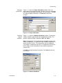
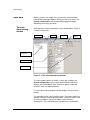
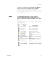
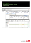
® DriveWare User Manual DriveSize DriveSize User Manual DriveWare Code: 3BFE 63980463 Rev Y EFFECTIVE: 12.09.2011 SUPERSEDES: 22.12.2010 FIDRI\ENT 00000073.DOC 2011 ABB Oy / Drives. All rights reserved. Table of Contents Table of Contents.................................................................................................................................................i Chapter 1 – Overview of DriveSize .................................................................................................................1-1 Overview ..................................................................................................................................................1-1 Hardware and system requirements ........................................................................................................1-1 Installing DriveSize ........................................................................................................................1-1 Running set-up ..............................................................................................................................1-1 Conventions used in this manual .............................................................................................................1-2 Program structure ....................................................................................................................................1-3 DriveSize functions ..................................................................................................................................1-3 DriveSize Help .........................................................................................................................................1-4 Chapter 2 – Dimensioning...............................................................................................................................2-1 Overview ..................................................................................................................................................2-1 Starting a new project ..............................................................................................................................2-1 Selecting a product series..............................................................................................................2-2 Changing project data.......................................................................................................2-3 Selecting ambient conditions ............................................................................................2-3 Input data .................................................................................................................................................2-4 The main dimensioning window.....................................................................................................2-4 Toolbar...........................................................................................................................................2-5 System configuration .....................................................................................................................2-6 Network and Transformer data ......................................................................................................2-6 Motor input data.............................................................................................................................2-7 Selecting load type and duty cycle....................................................................................2-7 Entering motor speeds and loads .....................................................................................2-8 One-time overload at start ..............................................................................................2-10 Changing motor specifications ........................................................................................2-11 Additional derating requirements .................................................................................................2-12 Reinforced insulation ......................................................................................................2-12 Terminal boxes ...............................................................................................................2-13 Inverter input data........................................................................................................................2-13 Entering inverter load......................................................................................................2-13 Changing inverter specifications .....................................................................................2-14 Select liquid cooled inverter ............................................................................................2-15 Line supply unit input data ...........................................................................................................2-16 Entering line supply unit load ..........................................................................................2-16 Changing line supply unit specifications .........................................................................2-17 Selecting liquid cooled supply unit ..................................................................................2-17 System configuration..............................................................................................................................2-18 Names of units ................................................................................................................2-18 Inserting, copying or deleting components......................................................................2-18 Highlighting components.................................................................................................2-18 Dragging and dropping ...................................................................................................2-19 Automatic track ...............................................................................................................2-19 Opening a saved project ........................................................................................................................2-21 Opening a project file ......................................................................................................2-21 Changing the Drive and the Directory path.....................................................................2-21 User’s Manual i Table of Contents Chapter 3 – Special Features ..........................................................................................................................3-1 Overview ..................................................................................................................................................3-1 Motor Load...............................................................................................................................................3-1 Custom Duty Cycle ........................................................................................................................3-1 Line supply unit load ................................................................................................................................3-2 Customer specific motors.........................................................................................................................3-3 Existing motors.........................................................................................................................................3-3 User motors .............................................................................................................................................3-4 Creating user motors File..................................................................................................3-4 Importing from file .............................................................................................................3-4 Entering loadability curves ................................................................................................3-6 Import motor loads… ...............................................................................................................................3-6 Chapter 4 -Results ...........................................................................................................................................4-1 Overview ..................................................................................................................................................4-1 Dimensioning results................................................................................................................................4-1 Result display...........................................................................................................................................4-2 Efficiency report ................................................................................................................4-4 Graph display ...........................................................................................................................................4-4 User selection display ..............................................................................................................................4-5 List of Selected.........................................................................................................................................4-8 Chapter 5 – Network Check.............................................................................................................................5-1 Overview ..................................................................................................................................................5-1 Network Check display.............................................................................................................................5-1 IEEE and IEC Standards ...............................................................................................................5-1 Calculate harmonics ......................................................................................................................5-3 Chapter 6 - Printing..........................................................................................................................................6-1 Printing the Results ..................................................................................................................................6-1 Efficiency Report ......................................................................................................................................6-1 Network check Report..............................................................................................................................6-1 ii User’s Manual Chapter 1 – Overview of DriveSize Overview This chapter tells you how to install and start the DriveSize program. It also provides general information about using DriveSize. This manual instructs you on how to use DriveSize for selecting proper motors and drives. This manual covers the variable speed drives (VSD) based on AC technology. DriveSize installation might include components for direct on line motors (DOL), machinery drives (ACSM1) and DC Drives – they have their own manuals. To use this manual you should have basic knowledge: Hardware and system requirements • Terminology of electrical AC drives • ABB product names • Load torque, power and speed requirements. To operate DriveSize, your computer must meet the following minimum requirements and have the following hardware and software installed • IBM compatible PC with Pentium 4 or higher • 512 MB RAM minimum • Windows 2000 or XP with Internet Explorer 5.0 or later • Hard Disk space of 250 MB • Microsoft Excel 97 or later for printing • Microsoft Data Access Components 2.7 or later • .NET Framework 3.5 SP1 or equivalent Installing DriveSize The software installation copies all the necessary files to the user specified drive and directory. The set-up program prompts you to install the software to a directory called C:\ProgramFiles\DriveWare \DriveSize. You can change the directory. The set-up program also makes a working directory called C:\ProgramFiles\DriveWare\ DriveSize\Data\Projects where all of your projects will be stored. Running set-up To start the set-up program: User’s Manual 1. Start Windows. 2. Insert the DriveSize CD into the appropriate drive or download the setup package to your local hard disk. 1-1 Overview of DriveSize 3. Select Run from the Program Manager’s File menu. 4. Type the drive letter of the drive followed by “:\DriveSize33.exe”. Click OK, or press ENTER. 5. Follow the instructions the Set-up program gives you. If you have problems installing the DriveSize, close any other programs that are running. Restart Windows and do not open any programs before installation is completed. Before reinstalling, uninstall the old version of DriveSize. Always disable MCAfee Host Intrusion Prevention System (HIPS) both while installing and uninstalling of DriveSize. Conventions used in this manual The table below lists the terms and conventions which have special meaning throughout this manual. Base speed Mechanical speed where the base power is required. Base power Mechanical power. Also used as the base value for overloads. Overload Defines maximum required power for short durations. The power is overload % X base power. Overload % is normally positive, but a negative value means the overload has a different sign than the base power. One-time at start overload This overload type is allowed once, for instance, at start. Before the next start it is assumed the frequency converter has cooled down to the ambient temperature. Motoring bridge The bridge of the line supply unit which is used when power flow direction is from the network to motors. Generating bridge The bridge of the line supply unit which is used when power flow direction is from the motors to the network, and the motors are generating power. Line-up Consists of the supply unit and inverters, which have a Common DC-bus. IC International Cooling. IP International Protection. TempRiseClass Temperature Rise Class of motor. TSU/DSU/ISU Thyristor Supply Unit/Diode Supply Unit//IGBT Supply Unit. LC Liquid cooling. 1-2 User Manual Overview of DriveSize Program structure DriveSize consists of a user interface with dimensioning functions, and product databases which contain catalog motors and frequency converters and the units/modules of frequency converters. The dimensioning of customer specified motors is based on ABB Sophiè, which has been developed by ABB Oy / Machines. ABB Sophiè is included in the DriveSize installation package. The program follows the common user interface guidelines of Windows. Select first one of the AC Drive product series and the associated product database opens. The dimensioning cases are called projects. You can save the selection results for the project into their own project file (XML-file). You can then generate technical reports in Excel format which you can attach to the project and drives documentation. DriveSize functions DriveSize offers several functions for dimensioning the drive. All of the functions are available on the main menu bar or toolbar. This manual also describes other ways to access these functions. DriveSize contains the following items for dimensioning: • Ambient conditions (There are separate functions for the conditions of drives and motors) • Motor temperature rise class • Motor load types available: Constant power Constant torque Constant torque & power Squared torque (Pump/fan) • Overload types available: One-time at start Simple cyclic Multiform cyclic • Supply unit power factor • Network harmonics calculation Harmonics for any inverter or supply unit Combined harmonics User Manual • Thermal loss calculations for motor, inverter and supply unit • Supply unit specific total mass flow and dissipated losses for liquid cooled multidrives 1-3 Overview of DriveSize DriveSize Help 1-4 • Results in numerical form • Results in graphical form (load, motor, inverter) • Selecting an alternative inverter, a motor and a line supply unit • Imperial and metric units • Generating reports in Excel format for saving or printing • Saving and recalling dimensioning cases • Saved information is in XML format and can be used with other software DriveSize HTML help includes information on how to use the program and make dimensioning for a drive. You can access the DriveSize Help through the Help menu or by pressing F1. The DriveSize Help is context sensitive and when F1 is pressed, the help automatically opens a help window associated with the active function of the program. User Manual Chapter 2 – Dimensioning Overview This chapter shows how you make dimensioning or recall a previously saved project file. Starting a new project You can make a complete drive system design with DriveSize in many ways. The following list is an overview of the tasks you can perform with DriveSize. Later on you will learn shortcuts to perform the same tasks more quickly. • Double click a product family or select one and click Open from New Project Selection (See Figure 2 – 1). • Select Project Info from File menu. Enter project information, or click OK to skip this section (See Figure 2 – 2). • Select Ambient Conditions from Data menu. Set ambient conditions, or click OK to accept defaults (See Figure 2 – 3). • Enter the primary voltage and select a suitable frequency (See Figure 2 – 4). Frequency has linkage to secondary voltages. • Highlight a transformer in System configuration and select a secondary voltage (See Figure 2 - 5). • Highlight the motor in System configuration and enter load definitions (See Figure 2 - 6). DriveSize then selects the motor. If you want to change the motor, use the User selection functions. • DriveSize selects the frequency converter or inverter once the motor/motors are known. Drive systems may contain more than one inverter, and each of these need to be selected. You can also select your own frequency converter or inverter. • For a multidrive product series, the dimensioning of line supply unit is done after all the inverters and motors have been defined. Note: The supply unit type also affects the motors. In System configuration, use a toolbar icon or a menu command or press Ctrl-D to control the dimensioning for a selected unit. You can make dimensioning one by one (Ctrl-D) or all units at same time (CtrlA). User’s Manual 2-1 Dimensioning Selecting a product series When you start DriveSize without a project file a Welcome window opens. If you are starting a new project you must select a product series first. Figure 2 – 1 shows the Welcome window. Figure 2 - 1 New Project Use Project Info from File menu and Ambient Conditions from Data menu if you want to change the defaults. You can change this information later with menu commands. 2-2 User Manual Dimensioning Changing project data Figure 2 - 2 shows the Project Information window. Enter new project data to the specified text box. DriveSize saves this information when you save your project and includes it on your reports. Click OK to accept the project information. Click Cancel to discard the changes. Figure 2 - 2 Project Information Selecting ambient conditions Figure 2 – 3 shows the Ambient Conditions window. To change the ambient conditions type new data to the appropriate text box. The practical range for altitude is between 1000m and 4000m. Note: The dependency of the altitude to the loadability changes with different components. The practical range of ambient temperature is mostly from 30°C to 50°C. This also changes with the component. For example, a temperature up to 55°C is accepted for marine drives but Ex motors are not selected at all if the ambient temperature exceeds 40°C. Click OK to accept the project information. Click Cancel to discard the changes. Figure 2 - 3 Ambient Conditions User Manual 2-3 Dimensioning Input data The main dimensioning window Motors, inverters, line supply units, transformers and the network have different data input displays. When you click on an item in the System configuration field, the input data display will change depending on the item you select. After opening or creating a project the main window opens. Figure 2 4 shows its main parts. Title bar Menu bar Toolbar Ambient conditions System configuration Input data Selected data Figure 2 - 4 The main dimensioning window The main window contains a title bar, a menu bar, a toolbar, the System configuration field, an input data field and a field which displays your selected data. Each field has a specific usage and functions, which are explained below. The main dimensioning window’s title bar displays the name of the project. The menu bar contains the DriveSize menus. Each menu contains a group of selections, each of which performs a specific function. Click on a menu to open it. You can also open a menu with key combinations. Press the Alt key plus the letter that is underlined in 2-4 User Manual Dimensioning the menu’s title. To choose a menu selection, press the appropriate letter, or use the cursor keys to highlight it and press ENTER. You can also access many of DriveSize's functions from the keyboard by using key combinations. These combinations are called short-cut keys. The short-cut key for a command appears to the right of the command in the menus. Toolbar The Toolbar provides quick access to common commands in DriveSize. Toolbar buttons perform a function just like a menu selection. To perform the function of a certain button, click the button on the toolbar. Tip: When you move the cursor over the button the help text for that button appears below it. Table 2 - 1 Toolbar icons Icon User Manual Action Menu equivalent Opens a new project. New... command under File menu. Opens a project. Open... command under File menu. Saves the project... Save... command under File menu. Shows the Print dialog. Print... command under File menu. Shows the Ambient Conditions display. Ambient Conditions… command under the Data menu Show the Overload Definitions display Overload Definitions… command under the Data menu Shows the Network Check display. Network Check... command under the Tools menu Dimensions the selected item. Make Dimensioning… command under the Tools menu. Shows the dimensioning Results display. Dimensioning Result... command under the Result menu. Shows the Graph display. Graphs... command under the Result menu. Shows the Selected Unit display. List of Selected... command under the Result menu. Shows the User Selection display. User Selection… command under the Tools menu. 2-5 Dimensioning Table 2 - 2 Ambient conditions on the toolbar Picture Meaning Indicates the installation’s altitude. It is common to all components. Indicates the transformer’s ambient temperature. Indicates the motor’s ambient temperature. Indicates the drive’s ambient temperature. System configuration The System configuration field gives you an overview of the drive system as well as the type designation or name of each unit in the Tree structure list. Figure 2 - 4 shows an example of a multidrive tree where no selections have been made yet. Motor load, Inverter load, Line supply unit load, Network data and Transformer load view appears in the input data field depending on which drive component you select from the system configuration. After you select drive components, the catalog data for the motor, the inverter, the line supply unit or the transformer appears in the selected data field depending on which component you select from the system configuration. Network and Transformer data The primary voltage does not affect motor and drive choices but if you select a value which is too high it prevents you from selecting a transformer. The default system frequency is 50Hz but will change to 60Hz if valid. Default system frequency has a direct effect on possible secondary voltage levels as well as on the motor databases. The logic of DriveSize means that in 60Hz countries the standard motors are 60Hz motors. This limitation is not valid with AC Drives. Short circuit power is essential when network harmonics are calculated. DriveSize has a practical upper limit for short circuit power. Figure 2 - 5 shows the Network data and Transformer load dialog. DriveSize calculates the transformer load power from the motor base powers and efficiencies and power factors. You can allow DriveSize to use these values, but in special cases you can use your own values. 2-6 User Manual Dimensioning The software includes Oil immersed and Vacuum Cast Coil Dry type of transformers. Figure 2 - 5 Network data and Transformer load definition Motor input data Selecting load type and duty cycle DriveSize supports four load types: A) Pump & Fan B) Constant torque C) Constant Power D) Combination of constant torque and power (This specifies the torque versus speed characteristics of the base load and overloads.) Note: ACS550 only supports type A and ACQ810 supports types A and B. In most cases DriveSize supports the following overload types: A) Simple cyclic B) Multiform cyclic C) One-time at start User Manual 2-7 Dimensioning Only overload type C with fixed 10 s overload time or 10s/600s simple cyclic overload are allowed for Ex motors. Simple cyclic assumes overloads which will last for specified overload durations every specified cycle time. Note: The overload is assumed to happen anywhere between minimum speed and maximum speed. If you choose Multiform cyclic, the Overload definitions dialog opens. You can also open it from the toolbar by selecting, for example, Duty cycle. The Overload definitions are explained in detail in Chapter 3- Special Features. Electrical braking (negative base power and/or overloads) is possible with TSU or ISU. Entering motor speeds and loads The Motor speed and Motor load input fields vary with different load types. DriveSize does not accept gear information. If a gear is involved convert those values to motor speed manually or use Excel. DriveSize does not consider dynamic torques when it accelerates inertias up and down. When remarkable dynamic torques happens, include them as short term overloads. Base speed Base speed is the minimum mechanical speed of a motor where the base power is required. Note: Use exact values for base speed. Use 1456 (not 1500) because the rated speeds of motors are also exact. Base power Base power is the mechanical power of a motor. This is used as the base value for all overloads. Use RMS-power or thermally equivalent power when you do not know the base power. You can also use a round number like 10kW, 50kW or 100kW and type in overloads based on the base value you select. In this case check later that the motor can handle the load cycles thermally. Base power is normally positive but negative values are acceptable. Fill in the required load that is on the shaft – not the rated power of the motor. Specify the real required shaft power of the loading machine. In VSD applications the motors are always slightly derated. Base overload Base overload defines the maximum required power together with base power for overload time. The power is overload % X base 2-8 User Manual Dimensioning power. Overload % is normally positive but a negative value means the overload has a different sign than the base power. Min speed If a min speed is too low, DriveSize will select a size for motors and drives that is larger than necessary. The min speed in DriveSize is not exactly the minimum speed of the motor but a speed which is used without interruptions of, for example, 30 minutes. DriveSize assumes the duty cycle will continue without stopping and DriveSize selects the motor and drive accordingly. If minimum speed was critical, you can see it from results/graphs. The default min speed is 300 RPM or 400 RPM. Max speed A max speed that is too high might have a negative impact on motor size. If the max speed is much higher than the base speed and overload% is high, the absolute maximum torque of the motor can be a limiting factor. Overload at max speed Due to the reasons stated above, the overload% at max speed can be given a different – normally lower - value than the overload% at base speed. This is valid for constant power load types. User Manual 2-9 Dimensioning Motor load inputs Overload time Motor specifications Figure 2 - 6 Motor Load and Specifications Data One-time overload at start Figure 2-6b shows where you select the values for One-time overload at start. OL% The starting torque is OL% X base torque. Base torque is calculated from base power and base speed. The valid range for OL% is 1% to 1000%. OL time is the duration of starting overload in seconds. OL max speed tells DriveSize at which speed the overload will cease. Use low values. If OL max speed is equal to the base speed and OL% is high, the power limit of the inverter might force DriveSize to select a larger frequency converter. 2 - 10 User Manual Dimensioning Figure 2 – 6b Motor Input Data Changing motor specifications You can adjust the specifications for the motor such as number of motors, the preferred motor type, frame material, IP class, IC class, temperature rise class and so on. Click on the item to change a selection. The first item on the following list is the name To see Name in System configuration, go to Tools, select Options…, then select the Unit name radio button. DriveSize shows the type codes of motors. Table 2 - 3 Options for Motor Specifications Specification Name Motors per inverter User Manual Options Any text or string 1 ... 100 per inverter unit. > 1 = MultiMotor Case, a factor DriveSize considers when it selects an inverter. The load is given for one motor. One inverter feeds several motors 2 - 11 Dimensioning connected in parallel. Process performace - software selects Process performance by deault including HXR, AMA&AMI motor. The following Motor types are not included in Auto selection: Existing, Industrial performance, General, PM motor, Flameproof, Non-Sparking, Dust ignition proof, Marine, User defined. FrameMaterial Not Specified, Aluminum, Cast iron, Steel. You can limit the motor families. Family Limits the search to one family only, such as M3BP. Pole number Pole number can be Automatic or one of the following: 2,4,6,8,10 or 12 Design Read more about Design from motor user manuals. Connection Currently ignored. IP Class IP55, This does not impact the selection IC Class IC411 self ventilated = cooling fan on motor shaft; means lower loadability at partial speeds IC416 forced ventilated = separate cooling fan. Choose this option for constant torque cases where min speed is very low. For large motors there are other choices available. Max speed rule Standard = standard max speeds is used, Metal fan = the higher speed limit of metallic fan is used. Separate fan = higher max speed available when force ventilated. Temperature rise B, F or not specified. Not specified means that DriveSize will use the class given in motor catalogs. Motor Tmax margin 43%, 30% or 20%. Motor catalogs give rough Tmax values and some margin has to be provided. The margin from actual overload torque to Tmax must be 43%,30% or 20%. Motor type Additional derating requirements Reinforced insulation 2 - 12 The mounting of terminal box and possible special winding insulation have an effet to the temperature rise of motor. These extra deratings are not taken into account in this software tool. It is assumed that standard insulation and top mounted terminal box are used. If not some extra margin shall be reserved. The necessity of derating could be also a sum of these both items. Reinforced insulation is recommended when motor voltage is higher than 500V. About three per cents (3%) additional derating of continuous loadability curve is required when reinforced windings are User Manual Dimensioning used. Please make sure margin shown in DriveSize is at least 3% for this purpose. Terminal boxes Terminal boxes are mounted either on the top of the motor, or on the left or right side. Availability of terminal box mounting option depends on the type of motor and a motor frame size. Three per cents (3%) additional derating is needed for continuous loadability curve when the terminal box is mounted on side of the motor or on the ND-end of the motor. Terminal boxes are mounted on the top of the motor as standard and then extra margin is unnecessary. Please make sure margin shown by DriveSize is at least 3%. Check the availability of force ventilation and accessories from motor manufacturer. Inverter input data Entering inverter load User Manual This section describes how to enter frequency converter/inverter data. Figure 2 - 7 shows the inverter input data. The load of the inverter is the motor currents and frequencies. The duty is the same as for motors. DriveSize calculates these load currents based on the selected motor characteristics (power factor, efficiency, pole pairs), the shaft loads, shaft speeds and motor voltage. You can change the inverter load value by entering new currents. 2 - 13 Dimensioning Figure 2 - 7 Inverter input data Table 2 - 4 Abbreviations used for inverter load. Abbreviation I continuous (A) I maximum (A) I max start (A) Changing inverter specifications 2 - 14 Meaning Continuous (base) current required from inverter. If you manually enter this value and if the motor is not known, DriveSize assumes the frequency range is wide. Maximum current required. If you manually enter this value and if the motor is not known, DriveSize assumes the frequency range is wide Maximum current at start for the inverter. You can adjust some specifications for the inverter, such as the inverter amount, type, IP class and pulse number towards network. User Manual Dimensioning Table 2 - 5 Options for inverter specifications (ACS800 SD) Specification Name Drive amount Type Construction Cooling IP Class Pulse Select liquid cooled inverter User Manual Options Any text or number string Number of parallel connected inverter and motor combinations. Auto selection includes ACS800 and ACS800 regenerative drives for all the constructions but modules and marine. You can limit the type with the following options: ACS800, ACS880, ACS800 regenerative, ACS 800 low harmonic, ACS850, ACS810 Wall-mounted only, Free standing only, Cabinet drives only, Marine drives only, drive modules only Air, Liquid. Notice that Liquid cooling is only available for Cabinet construction. IP00, IP21, IP22, IP42, IP54, IP54R, IP55. Depends on Type and Construction spesifications. 6 or 12. With 12-pulse the transformer must be a three winding type. Glycol concentration 0%, 30%, 50%. For liquid cooled units only. Liquid temperature 25°C…45°C. For liquid cooled units only. Select liquid cooled drive option from Cooling specification and two new specifications Glycol concentration and Liquid temperature appear. In case of multidrive; select liquid cooling for supply unit first. The cooling method of supply unit determines also cooling for all the inverters connected to that line-up. 2 - 15 Dimensioning Line supply unit input data This section describes the line supply unit data input (see Figure 2 – 8.) Motoring bridge load Calculated line supply unit load Line supply unit specifications Figure 2 – 8 Line supply unit input data Entering line supply unit load If you have selected the inverters, DriveSize calculates the supply unit motoring and regeneration powers. Change power and cycle time values. There are also fields for regenerative powers when the supply unit type is TSU or ISU. Table 2 - 6 Abbreviations used to describe the supply unit load. Abbreviation Pcont (kW) Pmax (kW) 2 - 16 Meaning Continuous power for the supply unit. Maximum power for the supply unit. User Manual Dimensioning Changing line supply unit specifications The default supply unit is six-pulse DSU cabinet type but other types and pulse numbers and IP classes are available. For thyristor supply units two additional parameters are available: the braking voltage and motor voltage. These parameters are mutually exclusive. Selecting liquid cooled supply unit Select liquid cooled (LC) supply option from Cooling specification and two new specifications Glycol concentration and Liquid temperature appear. These specifications determine also all the inverters connected to that supply unit. The cooling method of line supply unit is valid also for all the inverters connected to that line supply unit. Table 2 - 7 Options for Line Supply Unit Specifications Include Specification Name Type Options Any text or number string DSU cabinet, DSU module, TSU cabinet, TSU module, ISU cabinet, ISU module, LC DSU cabinet, LC DSU module, LC ISU cabinet, LC ISU module. IP Class IP00, IP21, IP22, IP42, IP54 Cooling Air, Liquid. This option determines also cooling method for all the inverters connected to that line-up. Pulse 6-pulse, 12-pulse, 18-pulse, 24-pulse (DSU, TSU). With 12-pulse the transformer must be a three winding type. 85, 90, 100 (TSU) A lower braking voltage means that prior to braking, the DC voltage is reduced. Braking Voltage (%) Motor Voltage (V) Glycol concentration User Manual Note: A lower DC voltage means there is less available motor voltage and therefore the maximum torque a motor produces will also be lower. This setting has to be understood in such a way that TSU will make a lower than nominal DC-voltage and motor voltages will also be lower. In this case, TSU can quickly change from motoring to regenerating. 380, 400, 415, 500, 525, 660, 690, 830 for 50Hz and 380, 440, 460,480,575, 600, 660, 690 for 60Hz. 0%, 30%, 50%. For liquid cooled units only. The supply unit determines also glycol concentration for all the inverters connected to that line-up. 2 - 17 Dimensioning Liquid temperature System configuration 25°C…45°C. For liquid cooled units only. The supply unit determines also liquid temperature for all the inverters connected to that line-up. The status icon in System configuration represents the status of the computing for the unit. Table 2 -9 describes the meanings of the status icons. Table 2 - 9 Status Icons Status SUPPLY UNIT Icon Meaning Line supply unit is not selected. Line supply unit is selected. Line supply unit selection is not valid. INVERTER UNIT Inverter unit is not selected. Inverter unit is selected. Inverter unit selection is not valid. MOTOR Motor is not selected. Motor is selected. Motor selection is not valid. Names of units 2 - 18 System configuration displays the type designation or unit’s name depending on what you have selected from Options. Inserting, copying or deleting components Use Insert and Edit from the menu bar when you want to insert, copy or delete components to the System configuration tree or when you want to remove any of them. If you want to copy- paste, you must, for example, highlight the frequency converter you want to copy and paste it on top of transformer. The pasted frequency converter will be the last item in the tree. Highlighting components When you click on an item in the System configuration tree, it is highlighted as your working item and the input data and possible selected item appear. User Manual Dimensioning Tip: You can highlight several components at one time. When you highlight several components at one time it is easier to copy (copypaste) or delete the group of components, or move (cut- paste) them from one line to another. To highlight components use Ctrl key, mouse and left mouse button. Press and hold down the Ctrl key when selecting the components. Figure 2 – 9 shows how to highlight components. Ctrl + mouse + left mouse button Right mouse button Figure 2 – 9 Highlighting several units at a time Dragging and dropping You can move an inverter or line supply unit to another location in the System configuration tree. Highlight the component you want to move. Press left mouse button, move the component to new location and release the mouse button. If you want to drag the unit, you must move each component separately. Automatic track User Manual 2 - 19 Dimensioning The program always keeps the dimensioning status valid. If you change some input data, which can affect the dimensioning of other units, then those dimensions will become not valid. Table 2 - 10 DriveSize Dimension Updating. Changed Data Motor ambient conditions Drive ambient conditions Network voltage Network frequency Supply unit load Dimensioning not valid for All motors, inverters and line supply units All inverters and line supply units All motors, inverters and line supply units All motors, inverters and line supply units Only the line supply unit whose load you changed Line supply unit All motors, inverters and line supply units in type, motor voltage that line-up or braking voltage Line supply unit IP Only line supply unit whose IP class you class changed Inverter load Only the inverter and line supply unit where the inverter is connected Inverter IP class Only that inverter and line supply unit where the inverter is connected Motor load Only that motor and inverter where the motor is connected. Also that line supply unit in that line-up Motor number, Only that motor and inverter where the motor type, IC class or is connected. Also that incoming unit in that temprise class line-up Inserting motor Only the line-up’s line supply unit and inverter Deleting or pasting Only the line-up’s line supply unit motor and inverter Dimensioning The inverter where the motor is connected. motor Also that line supply unit in that line-up Dimensioning Only the line-up’s line supply unit inverter 2 - 20 User Manual Dimensioning Opening a saved project When you open a previously saved project, a window shows all of the available projects in the selected path. When you highligh a file, you can view project information under Project info before opening the project. Figure 2 - 10 shows the Open File window. Figure 2 - 10 Open Project Screen Opening a project file Changing the Drive and the Directory path User Manual To open a project file highlight it or type its name to the File Name text box and click OK. You can also open a project file by double clicking its name on the file list. By changing the List of file Types option you can open projects which are based on different products. To change the directory path, double click on the path in the list on the right hand side of the window. If you are using a keyboard, you can push the spacebar to highlight the path. 2 - 21 Chapter 3 – Special Features Overview This chapter describes special features of DriveSize, such as making more sophisticated load definitions. This section also describes how to use special motors and how to create your motor database. Motor Load Enter motor load data in the main dimensioning window. If the project is more complicated, start from Overload definitions. Figure 3 - 1 Overload definitions Custom Duty Cycle Enter the duty cycle in the Load points table. Define the duty load by intervals and loads in percentage on top of base power or with power or with torque values. To enter these values click a cell in the table, and type the new value. To accept the value, press enter. Use the arrow keys on your keyboard to move inside the table. To accept your custom duty cycle click OK. If you click Cancel, you will lose all your changes. As you are entering the load's cycle parts, the Load graph shows you the defined custom duty cycle. Rms over the load cycle and worst 10 minutes Rms are always calcutated. When overloads are severe (long lasting) and thermally important DriveSize will compute a higher cont.load value which it will use as base power later on. User’s Manual 3-1 Special Features Table 3 - 1 Duty cycle display abbreviations. Abbreviation Rms Rms10 Highest load 100% Cont.load Overload Line supply unit load Meaning Rms – value for the whole duty cycle Rms – value for the duty cycle’s worst 10 minutes The highest load for the user’ s duty cycle Base power in kW Calculated continuous load kW Calculated overload % You often have to optimize a line supply unit selection and define the power requirements manually. There are fields for regenerative power when the supply unit type is TSU and ISU. The Pmax motoring power value is the sum of positive Pmax motoring values including losses. The same logic is used for Pmax generating, Pcont motoring and Pcont generating values as well. Figure 3 - 2 Line supply unit load. DriveSize fills time fields with defaults but you must check and, if necessary, modify the times and power values. DriveSize does not know the mutual timings of different inverters. 3-2 User Manual Special Features Customer specific motors Some motors are called customer specified because they are not picked from any list but the rated power and frequency are computed from load requirements. When you dimension a customer specified motor like HXR, AMA or AMI, ABB Sophiè automatically selects the number of poles and the field weakening point (Fwp frequency). After auto selection you can alter the value of field weakening frequency between given limits. Field weakening min and max limits are shown in selected motor data. Additionally there is also a value for maximum recommended (Rec). Before you change the value of Fwp frequency, select the pole number. When the value of the pole number is changed the Fwp frequency returns to Automatic. Figure 3 - 3 shows the drop-down list for a customer specific motor. ABB Sophiè automatically starts when the program cannot find any standard motor and Motor type is Auto selection or if you have selected motor type HXR, AMA & AMI motors. Figure 3 - 3 Drop-down list of field weakening frequency Existing motors User’s Manual You can define an existing motor in the Existing Motor dialog. It automatically opens when you select the Existing motor type. Figure 3 - 4 shows the dialog for an existing motor. The loadability curves of ABB standard motors are used for existing motors. DriveSize assumes that the existing motor is already installed and driving the load. The loadability of an existing motor is not checked, but you can see from the graphs if it is undersized according to the rules for standard motors. 3-3 Special Features Figure 3 - 4 Existing Motor dialog box User motors You can make dimensioning with motors from your own motor list. This section describes how you import your own motor database into DriveSize. The format of the motor list is an Excel worksheet with specified column headers and one row for the information of one motor. The motor list is expected to start on the first Worksheet in the book and the upper right corner is cell A1. Before you can use the motor list, import it to a UserMotor database in DriveSize. The import is always a full import and all previously existing User Motors will be removed when you import the new list. User motors are used independently from supply frequency but motor voltage must match supply voltage. The rating value conversion from one voltage to another is not done for user motors (user may do this by himself in Excel.) Different voltages must have separate rows in the database. 3-4 Creating user motors File Enter motor data and loadability curves to UserMotors.xls. You can find this file from your working directory located in C:\\ProgramFiles\DriveWare\DriveSize\VsdSize20\system by default. You can change the file name but not the extension. Importing from file To import new data to the database, go to File, select User motors and then select Import from file. This action overwrites the existing UserMotor database. User Manual Special Features Figure 3 - 5 Import Database window The import function validates the information in the Excel sheet before updating the database. Validating rules are: • Correct column headers • Correct data types (text, numeric) • All numeric values must be > 0 • Text values must fit into a max length • The frequency column must be between 8…400 (Hz) so that also values other than 50 Hz or 60 Hz are accepted. • The voltage must be one that DriveSize knows In case of import errors, the program will tell you which values were not accepted and the import will be cancelled. The date of imports is stored in the General table and they are visible in the About box. If there is at least one motor imported to the database, a new item is added to the Motor type list: User defined in the motor specification grid. When you select User defined, DriveSize updates the Family list with all families from the Database. The other specification items are: User’s Manual • Family: “Not specified”, +rest of list is from database • Polenumber: “Automatic”, 2, 4, 6, 8, 10, 12 • Design: Not specified, Basic, High-Output • Connection: Not specified, Y, D • IC class: IC411, IC416 • IM class: IM10001, … • Max speed rule: Standard 3-5 Special Features Entering loadability curves • Temp rise: Not specified, B, F • Motor Tmax Margin: 20%, 30%, 43% In the Excel list you can specify a reference to an existing loadability curve in the standard databases (for example IEC, Existing etc.) that is used when dimensioning. If an empty loadability curve name is found the existing motor type is assumed. You can also import the loadability curves for your motors. Use the same Excel file (UserMotors.xls) to import loadability curves. The loadability curve must start from zero frequency and extend to 1 (relative). The amount of loadability curves is unlimited. Import motor loads… You can import number of pre-collected loads at once. Enter motor loads to MotorLoadData.xlsx. You can find this file from your working directory located in C:\\ProgramFiles\DriveWare\DriveSize\ VsdSize20\system by default. You can change the file name but not the extension. • Load type: Pump/fan load or Constant torque • Speed, base: number in rpm • Power, base: number in kW • Overload, base: percentual value, relative to base power • Overload, time: overload duration in seconds • Overload repeating: total cycle duration in seconds After import motor loads appear to System configuration tree. You can make dimensioning, change specifications and save the results as usual. 3-6 User Manual Chapter 4 -Results Overview This chapter describes DriveSize's Results function. DriveSize usually selects the most suitable drive component. However, sometimes you may have to select another component. In these cases you can choose an optional component from the User selection list. Dimensioning results A general feature of DriveSize is that it will select some unit. The selection is not always optimal but it provides result quickly. When you change the input data you get another result. DriveSize computes the choices quickly but you make the final selection. Figure 4 - 1 shows an example of the motor results. System configuration Input data Selected data Figure 4 - 1 Main dimensioning window You can read the dimensioning results in the main dimensioning window, but you will find more detailed information from the dimensioning Result display, where results appear numerically or from the Graph display, where results appear graphically. If you are not satisfied with the software dimensioning result, make your own selection. This is possible in the User Selection display. All the individual sections dimensioned for the project can be viewed in the List of Selected display. User’s Manual 4-1 Results Result display The Result display shows results in numeric form for the item you have highlighted. The display is similar for motors, inverters and incoming units. The Specification data is about the user requirements. The catalogue data displays the unit and selection calculations in different points and shows how the unit meets the requirements. In the selection data there are columns for required, result and margin values. The required data are calculated from user load demands. The result data is calculated from the unit value of your process. The margin indicates the percentage of capacity still available (difference between the input requirements and the resulting data of the component). Figure 4 - 2 Result display for motors Table 4 - 1 Selection data for motors Point Torque (Nm) min, base, max Power (kW) min, base, max Overload (Nm) min, base, max Meaning Calculated torque at user-given speed: Minimum, base, maximum speed. Calculated power at user-given speed: Minimum, base, maximum speed. Calculated overload torque at user-given speed: Minimum, base, maximum speed for user defined time. Table 4 - 2 Selection data for Inverters Point Icont (A), Imax (A) or Imax start (A) 4-2 Meaning Calculated current load for an inverter in two situations: Continuous load and maximum load for user defined time. Maximum load at start is shown User Manual Results in case the load type is One time at start overload. Temperature Percent temperature margin of igbt module. There is also an additional temperature margin for other components like a choke when liquid cooled. Table 4 - 3 Selection data for diode or thyristor supply units Point Power (kW) mot cont, mot max, gen cont, gen max DC-current (A) cont motoring, max motoring, cont generating max generating Temperature mot temp, gen temp Meaning Calculated power load for an incoming unit for motoring and generating bridges in two situations: Continuous load and maximum load for user defined time. Calculated DC bus current with minimum voltage and power for motoring and generating bridges in two situations: Continuous load and maximum load for user defined time. Percent temperature margin for motoring and generating bridges. There is also an additional temperature margin for other components like a choke when liquid cooled. Table 4 - 4 Selection data for IGBT supply unit Point Power (kW) mot cont, mot max AC-current (A) cont motoring, max motoring Temperature mot temp Meaning Calculated power load for an incoming unit in two situations: Continuous load and maximum load for user defined time. Calculated current with minimum voltage and power: Continuous load and maximum load for user defined time. Percent temperature margin for supply unit. There is also an additional temperature margin for other components like an LCL filter when liquid cooled. Table 4 - 5 Liquid flow sums of line-up (ACS800 LC multidrives) Point Total flow (l/min) Heat loss (kW) User’s Manual Meaning Calculated total massflow for this line-up. The liquid flow of line supply unit is shown in the catalogue data table of LSU result sheet. Calculated loss power for that line-up. 4-3 Results You can see from the selection data the required load margin for the selected unit. When the margins are positive the unit meets the requirements. Note A large margin causes over-dimensioning. If the margin is negative, the unit cannot meet the requirements. When the motor type is ACS800, where a thermal model is used, the margin of continuous current can be negative when ambient temperature is below 40 °C. Efficiency report Graph display Click Efficiency Report push button in motor data sheet to see efficiencies and losses in printable form (see Figure 4 – 2). This sheet is available only for single drives. This display helps you check how well the unit fits the requirements. The graphs display load and motor torques, load and motor powers and load and inverter currents. Figure 4 - 3 shows the graph for load and motor torques as a function of speed. Figure 4 - 3 Graphs for motor On the display, a legend explains the curves. Each curve has its own color. 4-4 User Manual Results Table 4 - 5 Curves in the Load & Motor Torque graph Curve max. loadability max. load cont. loadability cont. load Meaning Motor maximum capability as a function of speed User defined maximum load (overload) Motor continuous loadability- thermal limit User defined continuous load Table 4 - 6 Curves in the Inverter graph Curve max. loadability max. load cont. loadability cont. load User selection display Meaning Inverter maximum capability User defined maximum Inverter continuous loadability User defined continuous load In the User Selection display you can select a smaller or larger unit instead of your current selection (made by the software or by your previous other choice selection). The selected unit has number 0 and its row is highlighted. Smaller units have a negative mark. Larger units have a positive mark. In this table there are some catalogue values and calculated margins to help with the new selection process. In some cases where the overloads are decisive there are no smaller units in the list. Figure 4 – 4 shows the view for other choice. This display is available for ABB standard motors, inverters and supply units. Figure 4 - 4 User selection display for motor. Table 4 - 7 Items in User selection display, motor table Item # PU User’s Manual Meaning Identity number Production unit 4-5 Results Type designation Power (kW) Poles Speed (rpm) In (A) Tn (Nm) Tmax/Tn Tcont margin Tmax margin Im (A) Immax (A) 4-6 The motor’s type designation Rated power Pole number Nominal speed Nominal current Nominal torque Maximum torque / Nominal torque Calculated cont. load margin. The smallest margin over the complete speed range. Calculated maximum load margin. The smallest margin over the complete speed range. Calculated continuous load current Calculated maximum load current User Manual Results Table 4 - 8 Items in the User selection display, inverter table Item # Type designation Apparent power (kVA) Power (kW) Icont (A) Margin Imax (A) Margin Selection method Temp. margin Meaning Identity number Inverter’s type designation. Inverter’s apparent power. Inverter’s nominal motor power. Nominal continuous loadability current. Calculated margin for your continuous load. Nominal maximum loadability current. Calculated margin for maximum load. Selection criterion. Calculated temperature margin. Table 4 - 9 Items in the User selection display, line supply unit table Item # Type designation Apparent power (kVA) Power fwd margin Current fwd margin Power rev margin Current rev margin Meaning Identity number Line supply unit’s type designation. Line supply unit’s apparent power. Calculated power margin for motoring load. Minimum of continuous and maximum load. Calculated current margin for motoring load with required power and minimum voltage. Minimum of continuous and maximum load. Calculated power margin for generating load. Minimum of continuous and maximum load. Calculated current margin for generating load with required power and minimum voltage. Minimum of continuous and maximum load. To select a different unit, click the row on which you want the unit to be listed. To verify your selection click OK. Your selection is highlighted. If you click Cancel, the selection is discarded. User’s Manual 4-7 Results List of Selected List of Selected displays the selected units. The list contains: Type designation, Unit name and Dimensioning status. Dimensioning status shows if you or the software has made the dimensioning. Figure 4 - 5 shows an example of this display. Figure 4 - 5 List of Selected 4-8 User Manual Chapter 5 – Network Check Overview This chapter describes how to compute the effects of drives on a network. Harmonics calculation is based on discrete Fourier transformation and tabulation. Network Check display With Network Check you can calculate: • the network harmonics and power factor for an individual frequency converter • the network harmonics and power factor for a line supply unit • combined harmonics for several units. Both the voltage and the current harmonics are calculated. DC voltage calculations provide DC-link voltage. Figure 5 - 1 shows an example Tip: Compute the combined harmonics, not harmonics for individual drives, because the parallel drives will smoothen and, in some cases, compensate each other. Combine ISU and DSU drives. Figure 5 - 1 Network Check window. IEEE and IEC Standards User’s Manual DriveSize calculates total harmonics distortion according to IEEE519 and IEC61800-3 standards. IEEE standard values indicate how much 5-1 Network Check the drive load affects the network at the point of common coupling. The rated current of transformer is used as load current. Note: In the IEEE standard, harmonics are calculated up to the 50th and in the IEC standard up to the 40th. Table 5 - 1 Network and Transformer Data Items Items Primary voltage Secondary voltage Frequency Network Sk Transformer Sn Transformer Pk Transformer Zk Supply cable type Cable quantity Cable length Meaning Network voltage on primary side Network voltage on secondary side Network frequency Network short-circuit power MVA –currently the max value is 900 MVA Transformer nominal power Transformer load loss power kW Transformer short-circuit impedance % Cable / Busbar Parallel connected cable quantity Length of the cable Table 5 - 2 Supply Unit Items Items Meaning Lac (µH) Ldc (µH) Cdc (mF) Pdc (kW) AC choke inductance DC link inductance DC link capacitance DC power, the default value is base power plus the losses in the motor and inverter. Table 5 - 3 Result Items Items cos ϕ1 Tot power factor Udc (V) Meaning Fundamental power factor, main wave power factor Calculated total power factor harmonics included. Calculated DC voltage Table 5 - 4 Harmonic Items Items Voltage THD (%) Current THD (%) N f (Hz) Current (A) In/I1 Voltage (V) Un/U1 5-2 Meaning Voltage Total Harmonic Distortion Current Total Harmonic Distortion Harmonic order number Harmonic frequency Harmonic current Harmonic proportional current to base current Harmonic voltage Harmonic proportional voltage to base voltage User Manual Network Check Calculate harmonics To calculate the harmonics, highlight the transformer and move to Network Check. If necessary, adjust the Pdc and other settings. Click Calculate. If you have not entered the network data in the main dimensioning window, enter the network voltage and frequency with deviations. Note: The network data you enter in Network Check does not affect the network data in the main dimensioning window. , To view the harmonics output as either a table or a graph, select the Table or Graph radio button in Show Mode. When you select the graph view, you can choose between voltage and current harmonics. User’s Manual 5-3 Chapter 6 - Printing Printing the Results You can use the printing functions for two purposes: • exporting the project information to Excel • printing on paper In the Print dialog define what information you want to move to Excel. DriveSize uses Microsoft Office Excel 97 English version or later for printing. Figure 6 - 1 shows the Print dialog. Figure 6 - 1 Print dialog Many DriveSize screens have a Report button. Click Report to print the screen data with Excel. Efficiency Report Click Efficiency Report push button in motor data sheet to see efficiencies and losses in printable form. Notice that print All Data Sheets does not contain Efficiency Report sheet. This sheet is available only for single drives. Network check Report Click Report push button in Network check view to see the printable result sheet of harmonics. Print All Data Sheets does not contain Network check Report sheet. User’s Manual 6-1 3BFE 63980463 Rev Y EFFECTIVE: 12.09.2011 ABB Oy Drives P.O.Box 184 FIN-00381 HELSINKI FINLAND Telephone Internet + 358 10 22 2000 http://www.abb.com/