1
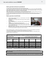
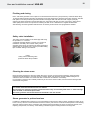
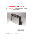
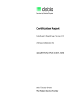
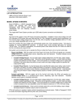
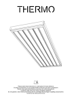
User and installation manual HNS–M2
STEAM GENERATOR
--
CONTROL PANEL
HNS – M2
--
Midi 2 / On Off push button
For home and professional use
314 SHS 99-3 A
User and installation manual HNS-M2
2
Contents
Specifications
3
Controls and accessories
3
Selecting the steam generator output for the steam room
3
General
4
Installation principle
5
Steam generator couplings
5
Electrical connections
7
Heating elements
7
Switch diagram
8
Steam generator 2 grade control
8
Steam generator maintenance procedures
9
Cleaning the steam room
10
Steam generator in professional use
10
Usage of steam generator HNS – M2
11
On/Off push button
12
Error messages
12
Installing control panel, push button and sensor
13
Troubleshooting
14
Troubleshooting table
14
ROHS
17
3
User and installation manual HNS–M2
Specifications
Operating voltage
230 V–240 V 1N~/2~,
230 V 3~,
400 V–415 V 3N~
(3.4 kW – 7.7 kW)
(3.4 kW–14 kW)
(3.4 kW–14 kW)
Output options
Enclosure class
Installation
Water tank material
Water tank pipes
Steamer dimensions
Weight when empty
3.4 / 4.7 / 6.0 / 7.7 / 9.5 / 12.0 / 14.0 kW
IP 20
Floor / wall
Aisi 304, stainless steel
Aisi 314, acid-resistant stainless steel
520 x 380 x 160 mm
about 11 kg
Easy to use
Floor or wall installation
Digital control panel Midi 2 (operating time can be set between 0–23 hours)
On/Off push button (alternative method of control, operating time fixed 30 min)
The installation of the control centre and On/Off push button in the steam room is allowed
Easy maintenance
Changeable resistors (3 pcs), of which 1 is fitted with a heat fuse.
Fill cap for chalk remover (citric acid) has been placed on the upper part of the steam generator.
Components easily replaceable, circuit board, heating elements, surface sensor.
Controls and accessories
Control panel Midi (0043256)
On/Off push button (0043211)
Sensor (0043210)
Scent pump, (Essence kit 0038130)
Scent pump canister 20 l (0038132)
Automatic flush and rinse cycle. (Automatic drain valve 4310130)
Steam nozzles (3.4–6.0 kW 1pc, 7.7–9.5 kW 2 pcs, 12–14 kW 3 pcs) (7819604)
Light adapter (0043214)
Selecting the steam generator output for the steam room
You can estimate the power requirement using the formula below.
3
Volume (m ) x K1 x K2 = Power requirement (kW)
Forced ventilation
K1 = 0.75
No ventilation
K1 = 0.52
Acrylic wall
K2 = 1.00
Light wall: board + tile
K2 = 1.25
Heavy wall: stone, concrete + tile
K2 = 1.50
Very heavy wall: stone, concrete + tile
K2 = 2.00
In heavy built steam rooms, it is recommended to use e.g. electric heating cable for warming the seats,
walls and floors.
Output
kW
Light structure, acrylic,
tempered
glass
No A/C
Heavy wall,
concrete,
stone
Light board
wall + tile
3,4
2 – 7 m³
Air conditioned
2 – 6 m³
4,7
3 – 8 m³
6,0
No A/C
No A/C
Steam
kg / h
2 – 6 m³
Air conditioned
2 – 5 m³
2 – 5 m³
Air conditioned
2 – 4 m³
5
3 – 7 m³
3 – 7 m³
2 – 6 m³
2 – 6 m³
2 – 5 m³
6
4 – 13 m³
4 – 9 m³
4 – 8 m³
3 – 7 m³
3 – 7 m³
3 – 6 m³
8
7,7
6 – 15 m³
6 – 11 m³
6 – 10 m³
5 – 9 m³
5 – 9 m³
4 – 8 m³
10
9,5
9 – 17 m³
9 – 13 m³
9 – 14 m³
8 – 13 m³
7 – 11 m
6–9m
13
12,0
12 – 24 m³
11 – 18 m³
11 – 20 m³
9 – 16 m³
9 – 16 m³
8 – 12 m³
16
14,0
18 – 30 m³
14 – 22 m³
14 – 24 m³
12 – 18 m³
11 – 17 m³
10 – 14 m³
19
Table for selecting a steam generator based on the steam room volume and wall materials.
User and installation manual HNS–M2
General
HNS-M2 steam generators are only intended for use in heating spa facilities. Using steam generators in other areas
than steam rooms can damage the building's structure.
The manufacturer is not responsible for damages caused if the unit has been used incorrectly or in a manner for
which the unit was not designed for.
Water and steam pipe connections must be made prior to connecting the unit into the mains.
Due care and attention must be taken when making the connections. Proper sealing must be ensured for all
extensions. A good extension must have at least taped over threaded connections, but it is recommended that
connections are soldered.
Ventilation
It is not normally necessary to arrange ventilation for steam saunas that are used for less than two hours. steam
rooms that are used for more than two hours at a time need ventilation for functional and hygienic reasons. The
3
ventilation recommendation is 10 to 20 m per person per hour.
If there is an empty space above the ceiling of the steam room, it must not be completely sealed off. Make at least
one ventilation hole (100 mm x 100 mm) into the empty space, on the same wall with the door.
The Supply air valve may be a hole in the bottom part of the wall with the door or a gap under the door.
The Exhaust valve is placed in the ceiling or on a wall near the ceiling as far from the supply air valve as possible,
however not above the door or the seats. The exhaust valve is connected to an air conditioning channel going
outside
Forced ventilation. If natural ventilation is not adequate (e.g. negative pressure in the room where the fresh air is
taken from), the steam room must be equipped with forced ventilation. Its output must be equivalent of 10 to20 m³ of
ventilation per person per hour.
Testing the water before using the steam generator.
The test packet that comes with the steamer includes test slips, which can be used for testing the water hardness
number as follows:
Dip the test slip in water for about 1 second, take it out and shake off the excess water. After a minute, compare the
colour code appearing on the test slip with the code key in the packet.
Test result:
< 3° dH,
> 4° dH,
> 7° dH,
> 14° dH,
> 21° dH,
Very soft water.
Soft water, Installing the decalcification device recommended
Medium-hard water, Install decalcification device and retest the water hardness.
Hard water, Install decalcification device and retest the water hardness.
Very hard water, Install decalcification device and retest the water hardness.
See page 9 for steam generator's operation time in hours before decalcification
The steam generator must be placed away from water and moisture (dry room). The room must be well ventilated as
the unit also produces heat. The maximum temperature of the room must not exceed 35°C. Recommended minimum
free space to sides and above the steamer is 30 cm. Adequate space for maintenance should also be planned for in
the placement of the unit. There should be a drain nearby for draining the tank.
The steam generator can be installed freestanding on the floor or on the wall using wall fittings. When using wall
fittings, ensure you use appropriate fittings and screws for the type of construction material of your walls. The steam
generator weighs about 17 kg when filled with water.
When the automatic drain valve is used, it is recommended you use wall installation so an adequate angle can be
ensured for draining of water.
4
5
User and installation manual HNS–M2
Image of principle of installation
Sensor
Steam room
520
Control panel
16
0
Water connection
380
1700mm
Power
supply
On/off push button
Steam pipe
Flushing
Locating the control panel
Generator wall mounting
Control panel is installed inside or outside the steam room, model HNS – M2.
The cable of the control panel can be extended with an equivalent cable, max 10 m.
The On/Off push button can be used for remote starting and stopping of the steam generator, the push button can be
placed inside or outside the steam room. For more detailed instructions, see page 12
Steam nozzle/nozzles are fitted approximately 200 to 400 mm from the floor underneath a bench or a seat, or onto
the wall so that the hot steam cannot burn anyone's feet. The steam nozzles are aimed towards the floor. When the
nozzles are installed, you must ensure to place them somewhere where nobody can accidentally touch them. The
steam temperature is +100 °C and it can cause injuries on contact.
If children or people with impaired reflexes use the steam room, the steam nozzle must be fitted with a protector that
prevents people from being exposed to the hot steam shower.
Sensor. The sensor is connected with the steam generator circuit board to connectors T1 and T2 which identify it
automtically.
Sensor is installed at about 1,700 mm high, preferably on the wall opposite the door. It is recommended to seal the
sensor installation hole with appropriate sealing material, so that moisture cannot enter the wall structures.
The steam room thermometer is installed at such a height that it shows the same reading as the control panel.
Steamer connections
Lid nut
for decalcification
Steam pipe ½”
Water connection, ¾”
Automated electromagnetic valve
plug (HNS-M2)
Water draining ½ ”, manual
or electric valve
Main switch
Control panel cable
Power supply
User and installation manual HNS–M2
6
Water and steam pipe connections
Connect the flexible ¾” water connection tube in the packaging to the water connection in the installation panel of the
unit and to the cold water piping of the building. The water pressure must be between 0.2 and 10 bars. The water
supply pipe must have a manual stop valve for stopping water supply to the unit, if the unit is not used for a prolonged
time.
Installation must follow local regulations
It is recommended to use at least 18x16 mm (steam generator’s size 3.4 kW-9.5 kW) and 22x20 mm (steam
generator’s size 12.0 kW- 14 kW) copper pipe or a silicone tube of similar type when connecting the steam pipe. The
steam pipe diameter must be the same for the whole length.
The steam pipe must be tilted upwards or downwards from the steam generator to the steam room. There MUST
NOT be any water seals or water pockets. The condensation water forming in the steam pipe must be allowed to
drain freely to the steam room or back to the generator. If a fragrance pump is connected to the generator, the pipe
must ALWAYS drain away from the steamer, so that the chemicals cannot get into the tank.
Recommended maximum length for the steam pipe is 5 metres.
It is recommended to always use additional insulation for the steam pipe, for both safety reasons and to prevent
water condensation in the pipe.
Clearance from an uninsulated steam pipe to flammable material such as wood must be at least 10 mm.
WARNING: Hot steam can cause burn injuries.
The electromagnetic valve designed for discharging water from the steam generator tank (accessory: Automatic drain
valve) is installed on the downpipe, alternatively use manual flushing valve. Connect the downpipe (copper pipe with
a minimum diameter of 16 mm) to the downpipe of the steam generator. The downpipe is led to the nearest drain
outside the steam room. The temperature of the discharge water is 90–95 C.
IMPORTANT! No stoppers (valves, taps, etc.) may be fitted on the downpipe.
Regardless of where the downpipe is led, it must fall all the way from the steam generator to the drain. To ensure
adequate fall, you may have to place the steam generator on a wall mount or on a stand.
The steamer generator’s tank should be drained after each use. This extends the life cycle of the appliance
and reduces scaling and the need for repair.
The product’s warranty will be void if the steam generator has been incorrectly installed or it has been used
in a manner other than described in the user manual.
The warranty also expressly excludes operational faults if they are caused by hard water i.e. water with high
levels of chalk, or otherwise impure water.
The steam generator must be maintained as described in the user manual.
7
User and installation manual HNS-M2
Electrical connections
The sauna heater must be connected to the mains by a qualified electrician and in compliance with current
regulations. The steam generator is connected with a semi-permanent connection. Use H07RN-F (60245 IEC 66)
or a corresponding type cables
A
3 x 10
Generator connection cable
H07RN-F / 60245
IEC 66
mm2
230V 3~
4 x 1.5
Fuse
Room
size
A
3 x 10
Generator connection cable
H07RN-F /
60245 IEC 66
mm2
230V-240V 1N~/2~
3 x 2.5
A
16
m3
1,5 – 2,5
5 x 1.5
3 x 10
4 x 2.5
3 x 16
3 x 6.0
25
2,5 – 5
6.0
5 x 1.5
3 x 10
4 x 2.5
3 x 16
3 x 6.0
25
5–7
7.7
5 x 2.5
3 x 16
4x6
3 x 25
3 x 10
35
7 – 10
9.5
5 x 2.5
3 x 16
4x6
3 x 25
------
------
10 – 12
12.0
5x6
3 x 25
4 x 10
3 x 35
------
------
12 – 15
14.0
5x6
3 x 25
4 x 10
3 x 50
------
------
15 - 18
Output
3.4
Generator connection cable
H07RN-F / 60245
IEC 66
mm2
400V-415V 3N~
5 x 1.5
4.7
kW
Fuse
Fuse
*)
Main switch
There is a main switch at the bottom of one end of the steam generator, which is used only when the steam room is
not to be used for a long period of time.
The steam generator's automatic flushing and rinsing function will stop, if the power is switched off.
(Optional, Automatic drain valve)
Steam generator's heating elements
Teho
Power
Leistung
Vastus / Element / Heizstäbe 230V
1
2
3
3.0
1000W/SEPD 131
1000W/SEPD 130
1000W/SEPD 131
3.4
1150W/SEPD 97
1150W/SEPD 111
1150W/SEPD 97
4.7
1567W/SEPD 98
1567W/SEPD 112
1567W/SEPD 98
6
2000W/SEPD 99
2000W/SEPD 113
2000W/SEPD 99
7.7
2567W/SEPD 100
2567W/SEPD 114
2567W/SEPD 100
9.5
5250W/SEPD 116
3500W/SEPD 115
5250W/SEPD 116
12
4250W/SEPD 119
3500W/SEPD 115
4250W/SEPD 119
14
5250W/SEPD 116
3500W/SEPD 115
5250W/SEPD 116
8
User and installation manual HNS-M2
Connection diagrams
Contactor
3,4 - 7,7 kW 230 V 1N~ / 2~
Heating
elements
6
5
4
3
6
1
6
5
4
3
2
1. 1
2
3
4
6
5
5
2.
2
1
L2
L1 / N
4
3
2
Thermal
fuse
3,4 - 14 kW 230 V 3~
1
Main switch
Gr
2
Lid
grounding
4
5
6
L2 L3
L1
3,4 - 14 kW 400 V 3N~
1
2
N
PE
3
3
4
5
6
L1 L2 L3
Upper limit S2
Water valve
flush
230V AC
L
N
H1
N
H2
N
V1
N
V2
Water valve
filling
230V AC
OLEA 72
A K S1 S2 TX RX +5 0
N
White
Brown Serial traffic
Green to MIDI 2-controller
Yellow
LC1 LC2 B1 B2 T1 T2
Lower limit S1
White
Red
Surface sensor
White
Yellow On / Of
Green Push button
Brown
Sensor
Alarm 12 V DC
Light control option
max. 24 V DC, 50 mA
354 SHS 40 C
HNS – M2
3,4 – 7,7 kW
230V – 240V 1N~ / 2~,
230V 3~,
400V - 415V 3N~
HNS – M2
9,5 – 14,0 kW
230V 3~,
400V - 415V 3N~
Steam generator 2 grade control
Control of steam generator heat element has two grades.
Example: The set temperature is +43 °C. When the temperature reaches +43 °C, two elements are switched off with
the help of a contactor and one element retains the temperature with the help of another contactor. If the
temperature rises +1°C from the temperature set, all elements are switched off. When the temperature drops below 1 °C, all elements are switched back on. This ensures stabile steam production for the entire duration of the
operation.
9
User and installation manual HNS-M2
Steam generator maintenance procedures
The water tank of the steam generator must be drained after every use.
To prolong its service life and to reduce the need for manual decalcification we recommend that steam generators
used in public facilities are connected to a water softening filter, which removes the calcium. This is especially
important if the water hardness exceeds 7° dH (German hardness).
Water softening filter must not generate foam or produce harmful chemicals, which may give erraneous view of the
water level in the tank and cause the heat coil fuse and heat elements to break.
In normal private use the need for decalcification is minimal, is the water is not particularly hard. However, the steam
generator must be decalcified at least once a year. This removes the calcium from the tank walls and heating
elements.
Steam generator decalcification
•
•
•
•
•
•
•
Start the steam generator and let it run until the water in the tank boils.
Stop the steam generator.
Detach the lid nut of the pipe that travels through the steam generator
lid. Caution
The lid nut is hot.
Pour the deliming agent (e.g. citric acid) into tank via the pipe using a
funnel.
Attach the lid nut to the pipe and let the agent work.
The steam generator flushes and rinses the tank automatically after
about 15 minutes and you can use the steam generator again. (Accessory: Automatic drain valve).
Manual flush valve:: After boiling, let the citric acid solution act in the tank for 15 minutes and flush the tank
after that by opening the flush valve. Close the valve after the first flushing and restart the steamer and allow
the tank to fill up with water. Repeat the process if necessary.
Citric acid deliming agent is odourless and harmless and it does not harm the steam generator's components.
If other type of deliming agent is used, bathing during decalcification is not allowed.
As can be seen from the adjoining chart, the need for manual decalcification depends on water quality, steam
generator output and operation time.
Operation time in hours before decalcification. A water softener must be used in public facilities to
reduce the need for manual decalcification. In addition, the automatic flushing valve (Automatic Drain
valve) must be used.
Hours of operation, different hardnesses
Steam generator
output kW
3.4 kW
4.5 kW
6.0 kW
7.7 kW
9.5 kW
12 kW
14 kW
Amount of
deliming agent.
Citric acid
(1 bag 50g)
2 bags
2 bags
2 bags
2 bags
2 bags
2 bags
2 bags
Softened water
Soft water
Medium-hard water
Hard water
1–3° dH
4–7° dH
8–14° dH
7000
3800
2600
2300
1300
900
900
500
300
350
190
130
1700
1500
1300
1200
600
500
400
300
200
180
160
150
90
80
70
60
0,01 – 1° dH
These service intervals are recommended by the manufacturer. Decalcification may be performed more
often, if necessary.
The steam generator is ready to be used right after the calcification treatment. If there is a lemon scent in the
steam room after the treatment, rinse the steam generator again. Use of citric acid is not hazardous to health.
User and installation manual HNS-M2
10
Flushing and rinsing
HNS – M2 steam generator has an option for an automatic flush and rinse cycle (Accessory: Automatic drain valve).
15 minutes after the steam generator has stopped or has been stopped, the electronic flush valve will open. After the
flush (takes 4 minutes) the steam generator will fill its tank again with cold water and flush it again (rinse). By
emptying the steam generator’s tank straight after use, the product will gain a long life cycle even in areas where
water quality leaves room for improvement. Flushing the tank is not a substitute for a regular decalcification.
After flushing, the steam generator will shut down to stand-by mode until the next programme is initiated.
Safety valve installation
The safety valve is installed on the steam pipe with using
the provided ½” T connector.
A separate downpipe directly to a drain or to the floor is
installed on the safety valve. NOTE: Safety valve's
downpipe must not be connected to the steam generator's
draining pipe or the steam pipe.. Use the provided sealing
tape or similar sealing on the threads.
Image.
Safety valve and flushing valve
(Automatic drain valve) installed.
Cleaning the steam room
Rinse the seats and the floor with warm water after every use (do not use a pressure washer). Clean the seats
regularly with mild detergent. Use ethyl alcohol or dilutine. Never use abrasives, strongly alkaline detergents or
solvents to clean the steam room seats and walls. Contact the manufacturer if necessary.
It is important to clean the floor carefully all the way to the corners. Use hot water, a brush and floor detergent that
removes dirt and grease.
The product’s warranty will be void if the steam generator has been incorrectly installed or it has been used
in a manner other than described in the user manual.
The warranty also expressly excludes operational faults if they are caused by hard water i.e. water with high
levels of chalk, or otherwise impure water.
The steam generator must be maintained as described in the user manual.
Steam generator in professional use
In addition to decalcification treatment, it is recommended to make a service plan for steam generators in daily use (6
hours or more). Service is recommended to be done 6 times a year and it is to include visual inspection of the heating
elements and the surface sensor, inspection and cleaning (lime accumulation) of the inner surface of the tank, and
replacing components, if necessary. Tank cleaning is done through the heating element mounting holes.
User and installation manual HNS-M2
Use of the steam generator HNS – M2
Control panel Midi 2 (RA 29)
Lighting controls
Temperature
display
Time display
Controls for temperature and
time.
Temperature sensor
On/Off button
Lighting controls Requires the light adapter 0043214 (sold separately) to function.
Temperature display Temperature range 30–50 °C.
Display of time remaining. Time setting 0–23 hours.
Use the plus button to increase temperature or time.
OK button accepts the modified setting or step forward e.g. for time settings.
Use the minus button to reduce the temperature or time.
On/Off button, to start or stop the steam generator.
11
12
User and installation manual HNS-M2
Three different uses of the controls
-
Control panel Midi 2
On/Off push button
Control panel Midi 2 and On/Off button together
Control panel Midi 2
The steam generator is started by pressing the On/Off button in the control centre. After that, the temperature display
starts to flash. The temperature may be set with the + and – buttons in one decree steps between 30 °C – 50 °C.
When the temperature figure on the display is correct, use the OK button to move to the time display or wait for three
seconds after which the time display starts to flash. Time can be modified in one minute steps during the flashing
using the + or - button up to 60 minutes after which the display will show hours up to 23. When there is 90 minutes
left, the display changes to minute display. Before that, only full hours remaining are shown. When there is five
minutes left, the time display starts to flash to indicate that bathing time is nearly over. You can use the On / Off
button to restart the steam generator if necessary.
The latest time and temperature settings are saved in the memory.
On/Off button function
If you use the On/Off button only, the steam generator will run for 30
minutes and stop automatically. You start the steam generator by pushing
the button. The LED light over the push button lights up to show that the
steam generator has started. Steam generator can be stopped by
pressing the push button even before the 30minutes has run out, in which
case the light turns off. Steamer can also be restarted, if desired.
Led light
ON - OFF button
A separate temperature sensor can be used with the steam generator, if
push the On/Off button controls are used.
The sensor prevents the temperature in the steam room from raising
above +50 °C. (Sensor 0043210)
See sensor installation on the next page.
Control panel Midi 2 and On/Off button together
You can use the On/Off button with the control panel in order to start or stop the steam generator when the control
panel has been installed elsewhere. Press the On/Off button for four seconds and the LED light on the push button
lights up to show that the steam generator has started. If you want to stop the steam generator using the On/Off
button before the time on the control panel has run out, press for four seconds and teh LED light will switch off. The
control panel is used to set the temperature and time required.
Lighting controls
Lights can also be controlled with the control panel light button, which lights the LED indicator lights by the push
button.
The steam generator connectors LC1 and LC2 on the circuit board are for lighting control. Connect the light adapter
connectors LC1 and LC2 to the corresponding connectors on th esteam generator circuit board. See for more
detailed instructions on the manual enclosed with the light adapter. (Accessory: Light adapter 0043214)
Error messages
E1 The steam generator surface sensor does not sense any water (filling time two minutes) or the water tap is turned
off when the stem generator is already running or something else is preventing the water from running into the steam
generator. Ensure that the steam generator gets water. If the problem is located in the steam generator, it may
require maintenance or repair.
E2 Error message appears when serial communication between the control centre and the circuit board is not
working.
Troubleshooting requires service.
The steamer stop after the error message. Fix the cause of the malfunction or call service. Malfunction can be
confirmed with the ON – OFF button.
In On / Off button equipped steam generators, the LED light flashes rapidly when the steam generator is indicating a
problem. The steam generator was started when the water tap was turned off or something else is preventing the
water from running into the steam generator. This notification appears when the steam generator is running, if water
intake is cut off. The error message can be confirmed with the push button. Fix the malfunction or have it fixed.
The circuit board has an output for alarm 24 V DC max 50 mA. The output is activated when E1 or E2 error message
appears on the display or when the led on the push button flashes rapidly.
13
User and installation manual HNS-M2
Control panel, Button and Sensor installation
55 mm
Mountin hole Ø 5 mm
Control panel frame is pressed directly on it.
Detaching is done with tool that comes with
the unit. The frame has small holes on the
edges. (4 holes) Push the locking pin lightly
with the tool through the hole, one at the time
and pull the frame outwards at the same time.
Locking
Locking
180 mm
150 mm
The control panel is filled with sealing material
making it moisture resistant. The control panel
may be installed directly on a wall. The pipe
hole in the steam room must be sealed to prevent
moisture from travelling through the pipe into the
structures. The cable is left behind the control panel.
The cable can also come out of the bottom of the
control panel, from a pre-marked hole.
Locking
Locking
The push button is filled with sealant therefore
it may be installed in the steam room. The push
button may be installed through a wall (acrylic
walls) or by making a suitable hole, where the
push button can be embedded and sealed with
appropriate sealant. Surface installation boxes
may also be used, if necessary, they do not
need to be tight, because the actual push
button is moisture resistant.
40 mm
32 mm
46 mm
wall
The sensor is installed at a height of 170 cm from
the floor preferably on the wall opposite the door.
A retaining nut can be used with an acrylic wall.
A hole can be made onto a thicker wall and seal it
with an appropriate sealant to prevent moisture from
getting into the structures.
Insert the sensor in the case and tighten the cable
using a clamping screw.
Locking screw
24 mm
32 mm
21 mm
Sensor
Locking screw
Sensors
casing
User and installation manual HNS-M2
14
Troubleshooting
WARNING! Steam generators may have several electric circuits.
Make sure that the device is completely dead before any troubleshooting operations.
Checks and troubleshooting.
In case of malfunction check that:
• the control panel and the steam generator are installed according to the connection diagrams
• the steam generator is installed properly according to this instruction manual
• the downpipe has adequate fall towards the drain
• the dirt filter is clean. The filter is in the incoming water connector. Open the pipe connector for cleaning, remove the
filter and remove all the chalk and dirt from it.
• there are no water pockets in the steam pipe or in the outgoing air conditioning pipe.
• there are no sharp bends in the steam pipe (bend radius must be at least 50 mm).
• any tap on the incoming water pipe to the steam generator is open.
• the steam room's structure and air conditioning match the installation and building instructions.
Troubleshooting chart
Possible causes and suggestions for fixes
Warming up takes abnormally long.
Cause: Inadequate power output of the steam generator. See output chart.
Action: Replace with more powerful steam generator.
Cause: Excessive ventilation of the steam room.
Action: Reduce ventilation so that it is 10-20 m³ per person per hour.
Cause: Blown fuse in the electrical cabinet
Action: Replace the fuse.
Action: Replace the heating element
Cause: The sensor is too close to the steam shower. See test 2.
Action: Move the sensor to another location or redirect the steam shower.
The steam room does not warm up or there is no steam.
Cause: Blown fuse in the electrical cabinet
Action: Replace the fuse.
Cause: No water is coming to the steam generator.
Action: Open the incoming water tap.
Cause: The control panel is not set up right.
Action: Check the time and temperature settings.
Cause: Dirt filter is blocked.
Action: Remove the dirt filter from the incoming water connector and clean it.
Cause: The electromagnetic valve for the incoming water is stuck.
Action: Remove the electromagnetic valve and clean it.
Cause: Too much chalk has accumulated in the steam generator's water tank. See test 1.
Action: Clean the water tank and surface sensor's pin, and replace the heating elements, if necessary.
Cause: The steam generator is connected for incorrect voltage.
Action: Check the voltage and the steam generator's connections. See Connection diagram.
Cause: The overheating protector has tripped. See test 4.
Action: Check and fix possible faults in the steam pipe, e.g. blocks caused by several sharp bends, water pockets or
significantly reduces inner diameter of the pipe. It is also possible that the tank has been filled with chalk accumulation or impurities. See the previous entry.
Cause: Fault in the circuit board, control panel or electromagnetic valve.
Action: Replace the faulty part.
User and installation manual HNS-M2
15
Warm water comes out of the steam nozzle, and there is little or no steam in the steam room.
Cause: The electromagnetic valve for the incoming water is stuck open because of dirt or electric fault. See test 3.
Action: Remove the electromagnetic valve and clean it. Fix the electric fault.
Cause: The electromagnetic valve is broken.
Action: Replace the electromagnetic valve.
Cause: Fault in circuit board.
Action: Replace the circuit board.
Warm water comes out of the steam nozzles in pulses or as weak continuous stream with steam.
Cause: Small water pocket in the steam pipe.
Action: Remove the water pocket.
Cause: Too much of the steam pipe is uninsulated.
Action: Insulate the steam pipe.
Warm water comes out of the steam generator's downpipe all the time.
Cause: Automatic electromagnetic flushing valve is stuck open.
Action: Stop the steam generator. Try again after 80 minutes. If the fault remains, remove the automatic electromagnetic flushing valve and clean it.
Banging noise from the water pipes when the electromagnetic valve opens or closes.
Cause: Inadequate connection in the water pipe coming into the steam generator.
Action: Mount the water pipe securely on the wall.
Cause: Recoil effect in the incoming water pipe.
Action: Install about 1 metre of pressure-proof reinforced rubber hose into the steam generator end of the water pipe.
Safety valve opens or the overheating protector trips.
Cause: Steam pipe is blocked. See test 4.
Action: Remove the block.
Cause: The inner diameter of the steam pipe is significantly reduced. See test 4.
Action: Replace the pipe or the connection where the inner diameter is reduced (minimum inner diameter is 16 mm).
Cause: Several sharp bends in the steam pipe. See test 4.
Action: Make the bends less sharp.
Cause: There is a large water pocket in the steam pipe. See test 4.
Action: Install the steam pipe so that a water pocket does not form.
Steam generation is irregular from the beginning.
Cause: The sensor is misplaced. See test 2.
Action: Move the sensor or redirect the steam shower.
Cause: Chalk or other impurities in the dirt filter.
Action: Remove the dirt filter and clean it.
User and installation manual HNS-M2
16
TEST 1.
Checking chalk deposits in the water tank.
Open the top lock nut in the steam generator. Lower a torch bulb that is connected to a battery with wires into the
opening and light up the water tank's inside. If there is more than 3 cm chalk on the bottom, the steam generator has
not been serviced and the chalk has not been removed according to the instructions.
It is also possible that the flushing and rinsing automation is not working. Check that the steam generator power has
not been switched off after bathing with a switch that may fitted in the supply line. You can switch the power off from
this switch only 80 minutes after the control panel has switched the power off.
Check the automatic flushing function by setting a bucket with a volume of about 12 litres under the downpipe. Start
the steam generator for about 15 minutes. Switch off the steam generator exactly the same way you normally do
after bathing. Wait at least 80 minutes and check if the bucket is filled with water. If it is not filled, there is a problem
with the steam generator's electric connections or the power supply has been switched off on the wire from electrical
cabinet directly to steam generator. It is also possible that the exhaust valve is blocked or the circuit board is faulty.
TEST 2.
Checking the thermostat sensor.
Wet a small towel with water and hang it on the sensor. If the steam generator starts producing steam within 20
minutes, the sensor works. However, it is placed in a wrong place or the temperature setting is too low. If the steam
production does not start, use the troubleshooting chart to find the fault.
TEST 3.
Checking the electromagnetic valve.
Stop the steam generator from the control panel. If water still flows from the steam nozzles 10 minutes after the
power has been switched off from the control panel, there is dirt in the electromagnetic valve. Remove the
electromagnetic valve and clean it.
If the water flow stops within 10 minutes after the power has been switched off from the control panel, the fault is in
the electrics (faulty connection or circuit board). It is also possible that too much chalk has accumulated in the water
tank. See test 1.
TEST 4.
Checking the steam pipe using the safety valve or the overheating protector.
Remove the steam pipe from the steam generator. Start the generator and let it run for about one hour. If the safety
valve or the overheating protector does not trip during the test, there is a block in the steam pipe that prevents the
steam flow. Follow the instructions in the troubleshooting chart.
The product’s warranty will be void if the steam generator has been incorrectly installed or it has been used
in a manner other than described in the user manual.
The warranty also expressly excludes operational faults if they are caused by hard water i.e. water with high
levels of chalk, or otherwise impure water.
The steam generator must be maintained as described in the user manual.
17
User and installation manual HNS-M2
ROHS
Ympäristönsuojeluun liittyviä ohjeita
Anvisningar för miljöskydd
Tämän tuotteen käyttöiän päätyttyä sitä ei
saa hävittää normaalin talousjätteen
mukana, vaan se on toimitettava
sähkö- ja elektroniikkalaitteiden kierrätykseen
tarkoitettuun keräyspisteeseen.
Denna produkt får inte kastas med
vanliga hushållssopor när den
inte längre används. Istället ska den
levereras till en återvinningsplats
för elektriska och elektroniska apparater.
Symboli tuotteessa,
käyttöohjeessa tai
pakkauksessa tarkoittaa sitä.
Symbolen på produkten,
handboken eller
förpackningen refererar till detta.
Valmistusaineet ovat kierrätettävissä merkintänsä
mukaan. Käytettyjen laitteiden
uudelleenkäytöllä, materiaalien hydöyntämisellä
tai muulla uudelleenkäytöllä teet arvokkaan teon
ympäristömme hyväksi.
Tuote palautetaan ilman kiuaskiviä ja verhouskiviä
kierrätyskeskukseen.
De olika materialen kan återvinnas enligt
märkningen på dem. Genom att återanvända,
nyttja materialen eller på annat sätt återanvända
utsliten utrustning, bidrar du till att skydda vår
miljö.
Produkten returneras till återvinningscentralen
utan bastusten och eventuell täljstensmantel.
Tietoa kierrätyspaikoista saat
kuntasi palvelupisteestä.
Vänligen kontakta de kommunala myndigheterna
för att ta reda på var du hittar närmaste
återvinningsplats.
Instructions for environmental protection
Hinweise zum Umweltschutz
This product must not be disposed with
normal household waste at the end of
its life cycle. Instead, it should be
delivered to a collecting place for the recycling
of electrical and electronic devices.
Dieses Produkt darf am Ende seiner LebensDauer nicht über den normalen Haushaltsabfall
Entsorgt werden, sondern muss an einem
Sammelpunkt für das Recycling von elektrischen
und elektronischen Geräten abgegeben werden.
The symbol on the product, the
instruction manual or the
package refers to this.
Das Symbol auf dem produkt, der
Gebrauchsanleitung oder der
Verpackung weist darauf hin.
The materials can be recycled according to the
markings on them. By reusing, utilising the
materials or by otherwise reusing
old equipment, you make an important
contribution for the protection of our environment.
Please note that the product is returned to the
recycling centre without any sauna rocks and
soapstone cover.
Please contact the municipal administration
with enquiries concerning the recycling place.
Die Werkstoffe sind gemäß ihrer Kennzeichnung
wiederverwertbar, Mit der Wiederverwendung,
der stofflichen Verwertung oder anderen Formen
der Verwertung von Altgeräten leisten Sie einen
wichtigen Beitrag zum Schutze unserer Umwelt.
Dieses Produkt soll ohne Steine und
Specksteinmantel an dem Sammelpunkt für
Recycling zurückgebracht werden.
Bitte erfragen Sie bei der Gemeindeverwaltung
die zuständige Entsorgungsstelle.