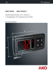
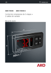
1
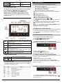
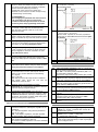
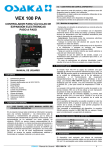
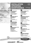
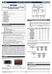
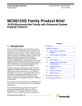
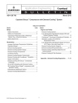
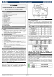
VEX 100 PA CONTROLLER FOR ELECTRONIC EXPANSION VALVES FOOTSTEPS The instrument shall not be used for purposes different from those described hereunder. It cannot be used as a safety device. Check the application limits before proceeding. Osaka Solutions reserves the right to change the composition of its products, even without notice, ensuring the same and unchanged functionality 1.3 – SAFETY PRECAUTIONS Check the supply voltage is correct before connecting the instrument. Do not expose to water or moisture: use the controller only within the operating limits avoiding sudden temperature changes with high atmospheric humidity to prevent formation of condensation Warning: disconnect all electrical connections before any kind of maintenance. Fit the probe where it is not accessible by the End User. The instrument must not be opened. In case of failure or faulty operation send the instrument back to the distributor or to “Dixell S.r.l.” (see address) with a detailed description of the fault. Consider the maximum current which can be applied to each relay (see Technical Data). Ensure that the wires for probes, loads and the power supply are separated and far enough from each other, without crossing or intertwining. In case of applications in industrial environments, the use of mains filters (our mod. FT1) in parallel with inductive loads could be useful. 2. GENERAL DESCRIPTION USER MANUAL CONTENT 1. 2. 3. 4. 5. 6. 7. 8. 9. 10. 11. 12. General warning General description Probes related to the VEX 100 PA Connections Front panel User interface Parameter list Forced opening Display messages Technical data Standard values Warranty 1. GENERAL WARNING 1.1 – PLEASE READ THIS MANUAL BEFORE USING THE DEVICE This manual contains the information necessary for proper installation and instructions for use and maintenance of the device, so please read the following instructions carefully. This documentation has been made with care, however, OSAKA assumes no responsibility for the use of it. The same applies to each person or company involved in the creation of this manual. This document is the exclusive property of which forbids any reproduction and disclosure and part thereof, unless it is expressly authorized. OSAKA reserves to provide functional changes at any time without notice.. 1.2 – PLEASE READ BEFORE USING THIS MANUAL This manual is part of the product and should be kept near the instrument for easy and quick reference. The VEX 100 PA module is able to drive a large variety of stepper electronic expansion valves. XEV22D permits to regulate the superheat (SH) of the fluid that runs into refrigerating unit in order to obtain optimized performance and a functioning of the evaporator independent by climatic or load conditions. VEX 100 PA modules are equipped with two probe inputs, one for 4 to 20mA or 0 to 5V pressure transducer and another one for NTC-EU, NTC-US or Pt1000 temperature probe. A LAN connection permits to transmit the pressure signal to others VEX modules in order to use only one pressure transducer in multiplexed cabinet applications. There are also two configurable digital inputs, the first one is free of voltage and the other ones is at high voltage in order to simplify connections with cooling request signal. With the useful display it’s possible to see the value of superheat (SH), the degree of opening of the valve or the probe values, the local keyboard allows programming the instrument without any other devices. To complete instrument equipment, a RS485 serial link permits to connect VEX 100 PA to Osaka monitoring and supervising systems. 3. PROBES RELATED TO THE VEX 100 PA PP 08 -0,5 .. +7 bar PP 10 0 .. +10 bar PP 30 0 .. +30 bar Temperature NTC 1 (IP68) -50 … +120 ºC PT 1000-FAST -50 … +110 ºC For other models of probes, consult catalogue Pressure 4.CONNECTIONS The instrument is provided with pluggable screw terminal block to connect cables with a cross section up to 2.5 mm2. Heatresistant cables have to be used. Before connecting cables OSAKA – User Manual - VEX-100-PA – V5 1 make sure the power supply complies with the instrument’s requirements. Separate the probe cables from the power supply cables, from the outputs and the power connections. Do not exceed the maximum current allowed on each relay, in case of heavier loads use a suitable external relay. 4.4 TEMPERATURE PROBE MOUNTING Advised temperature probe placement is illustrated in figure nearby. Between 0 and 180 inclination degrees respect to horizontal pipe section. 4.1 GENERAL WARNINGS Before connecting cables make sure the power supply complies with the instrument’s requirements. Separate the probe cables from the power supply cables, from the outputs and the power connections. 4.2 WIRING CONNECTIONS 4.5 PROBE CONNECTION 4.5.1 General warnings Pressure probe (4 - 20mA or ratiometric): respect the polarity. If using terminal ends be sure there are no bear parts which could cause short circuiting or introduce noise disturbance at high frequencies. To minimize the induced disturbances use shielded cables with the shield connected to earth. Temperature probe: it is recommended to mount the temperature probe on the outlet of the evaporator heat/exchanger and to isolate it properly to detect the gas outlet temperature. 4.6 CONFIGURABLE DIGITAL INPUT CONNECTION 4.3 WIRING GUIDELINE DEVICE TYPE Analog temp sensor and Digital Input RS-485 Network Pressure transducer Stepper valve Power loads and valve SUGGESTED CABLE AWG 22-2 SHIELDED, E.I. BELDEN #8761 AWG 22-2 SHIELDED, E.I. BELDEN #8761 AWG 22-2 SHIELDED, E.I. BELDEN #8761 Use valve manufacturer’s harness with a máximum length, not exceed 10 meters (30 feet). Allow a máximum wire size of 14 2 AWG (2 mm ) The superheat regulation is performed only when the cooling digital input is enabled. It’s possible to enable the SH regulation via: - Digital input 1, free voltage contact: Use the terminals (13-15), set the parameter i1F = CCL, its polarity it’s set by par. i1P. - Digital input 2 (8-9), main voltage contact Use the terminals (8-9), set the parameter i2F = CCL, its polarity it’s set by par. i1P Usually the digital input is connected to a thermostat or an activation contact OSAKA – User Manual - VEX-100-PA – V5 2 Liability Limitation 4.7 SUPPLY CONNECTION Power supply: VEX 100 PA is powered at 24Vac/dc. Use Class 2 transformer at list 20VA as the TF20(24) Connect transformer to terminals 11-12. All the pre-sets have been done according to the documentation available when the VEX 100 PA has been released, see below reference: Danfoss: - DKRCC.PD.VD1.C6.02 / 520H8021 @ Danfoss A/S (AC-MCI / sw), 2014-07 Sporlan: - 92008 / Bulletin 100-20 - RACE Catalogue 100-20-3 EDEV-2/UK - 02/2013 Emerson - FC-TD/ EX4-8 July 2008 In any case for each valve the only reference is given by the manual released by the manufacture together with the valve. Osaka Solutions can’t be considered responsible for any change made by the manufacturer and reported on the manufacturer manual. 4.8.2 Manual setting of valve To set the valve manually, act the according to the following procedure: a. Set tEP=0 b. Then set following parameters: LSt, USt, Sr, CPP, CHd according to the valve manual. 4.8 VALVE CONFIGURATION 4.8.1 Before connecting the valve - ALWAYS CONNECT OR DISCONNET THE VALVE WHEN THE CONTROLLER IS NOT POWERED - CONFIGURE THE VALVE ON THE VEX 100 PA BEFORE CONNECTING THE VALVE 1. BEFORE CONNECTING the valve, to avoid possible problems, configure the driver by making the right changes on the parameters. 2. The max distance between an VEX controller and a valve must not exceed 10 m. To avoid any problems, use only shielded cables with section greater than or equal to 0.325 mm² (AWG22). 3. Select the kind of motor (tEU parameter) and check if the valve is present in tEP parameter table reported here below. 4.9 VALVE CONNECTION 4.9.1 TERMINALS FOR VALVE CONNECTION 4 WIRES VALVES (BIPOLAR) Connection numbering 4 2 3 1 ALCO EX BLUE BROWN BLACK WHITE SPORLAN SEI-SEH WHITE BLACK RED GREEN DANFOSS ETS BLACK WHITE RED GREEN Válvulas 5-6 hilos (unipolares) Connection numbering 4 2 3 1 5 - Common EMERSON EX3 BLUE BLACK BROWN WHITE GREY SPORLAN SAGINOMIYA ORANGE RED YELLOW BLACK GREY ORANGE RED YELLOW BLACK GREY AFTER MAKING THE CONNECTION, PLEASE SWITCH OFF AND ON THE VEX CONTROLLER IN ORDER TO BE SURE OF THE RIGHT POSITIONING OF THE VALVE. 4.10 ABSOLUTE MAXIMUM POWER VEX100 PA is able to drive a wide range of stepper valves, in the following table are indicated the maximum values of current that the actuator can supply to the stepper wiring. The Osaka transformer to use is the TF20(24). NOTE: the electrical power absorption of the valve can be unrelated to refrigeration power that valve has. Before using the actuator, please read the technical manual of the valve supplied by the manufacturer and check the maximum current used to drive the valve in order to verify that they are lower than those indicated below. OSAKA – User Manual - VEX-100-PA – V5 3 VALVE TYPE BIPOLAR VALVES (4 wires) UNIPOLAR VALVES (5-6 wires) Maximum 0.9 A Maximum 0.33 A Current 6. USER INTERFACE Current 6.1 FAST ACCESS MENU (DURING REGULATION) 4.11 RS 485 SERIAL LINE All models can be connected to the monitoring and supervising system XWEB3000. If Mod=Std standard ModBUS-RTU protocol is used, if Mod=AdU custom XWEB library is required. This last configuration makes possible to use the same serial address of the thermostat that gives the cooling request to VEX. In this way, it’s possible to reduce the number of addresses used. 5. FRONTAL PANEL 1.- Press and release button. 2.- The variable available in the Fast Access menu are: CLP Cooling demand percentage tP1 Temperature from Probe 1 PPr Pressure value from Probe2 transducer. tP2 Suction temperatura obtained from pressure temperature table. SH Value of superheat StH Superheat set point oPP Percentage of valve opening d1S Free Voltage digital input status d2S Main Voltage digital input status VAC 3.- Brows parameter labels with and 4.- Press SET to see read-only value. To change parameter, press SET. 5.- To leave the fast Access menú, press and release SET + or wait for time-out to expire (about 3 minutes). NOTA: IF THE REGULATION IS NOT ENABLED THE CONTROLLER DISPLAYS “PMP”. 6.2 HOW TO SEE THE SET POINT (SP) 1.- Press the set buttons until the set point will be showed. 2.- To come back to see temperatura, wait about 5s or press newly SET key 6.3 HOW TO MODIFY THE SET POINT (SP) To display and to modify the set point. In programming mode its selects a parameter or it confirms a value. Push to display pressure to display the value 0..100% for valve opening a few seconds. A pressure to display the value of pressure for a few seconds. By pressing and releasing this key, it’s possible to see the values of the probes. In programming mode it slides the codes of the parameters or it increases their values. In programming mode it slides the codes of parameters or it decreases their values. SET % PRB SET + 6.4 HOW TO ENTERING “PR1” PARAMETER MENU To enter to “ PR1” level menu : 1.- Press SET + about 3 seconds.. 2.- Instrument shows first parameter in Pr1 menu. 6.5 HOW TO ENTERING “PR2” PARAMETER MENU COMBINACIÓN DE TECLAS + To change the set point value operate as follows: 1.- Press SET until the set point will be showed. 2.- Use and to change its value. 3.- Press SET to store the new value. To lock or to unlock the keyboard. To enter programming mode. 6.1 VEX100 PA LEDS To enter to “PR2” parameters list : 1.-Enter to “Pr1”. 2.-Select “PR2” parameter and press SET. 3.-The “PAS” label will be shown, then “0..“with 0 blinking. 4.-Insert “321” password through UP and DOWN buttons, then press set to confirm. On display there are some luminous dots. Their meaning is described in the following table: 6.6 HOW TO CHANGE A PARAMETERS VALUE To change the parameter’s value operate as follows: 1.- Enter the Programming mode by pressing the SET + button for about 3s. OSAKA – User Manual - VEX-100-PA – V5 4 2.- Select the required parameter. 3.- Press the SET button to display the value. 4.- Use and tochange the value. 5.- Press SET to store the new value and move to the following parameter. tEP Predefined valve selection: (0 to14) To exit: press and orwait 30s without pressing any button. NOTE: the set value is stored even when the procedure is exited by waiting the time-out to expire.. 7. PARAMETER LIST NOTE: All pressure parameters are relativesor absolutes depending on the PrM parameter. REGULATION FtY rEt PEo PEd tEU Kind of gas: type of gas used by plant. This is a fundamental parameter for correct functioning of all system. The table below contains the refrigerant gases managed by the XEV22D and their operating temperature LABEL REFRIGERANT OPERATING RANGE R22 r22 -50-60ºC/-58÷120ºF 134 r134A -70-60ºC/-94÷120ºF 404 r404A -50-60ºC/-58÷120ºF 47A r407A -50-60ºC/-58÷120ºF 410 r410 -50-60ºC/-58÷120ºF 507 r507 -70-60ºC/-94÷120ºF 47C r407C -50-60ºC/-58÷120ºF 47F r407F -50-60ºC/-58÷120ºF 290 r290-Propane -50-60ºC/-58÷120ºF CO2 r744-Co2 -50-60ºC/-58÷120ºF 450 r450A -45-60ºC/-69÷120ºF 513 r513 -45-60ºC/-69÷120ºF 448 r448A -45-60ºC/-69÷120ºF 449 r449A -45-60ºC/-69÷120ºF Reaction time (1÷100s; 0 = automatic time adjustment) time delay between valve position adjustments. It’s the time between the valve adjustment command and when the valve is moved. EI With rEt = 1 the valve is moved continuously, with rEt = 10 the valve is moved every 10s, with rEt = 0 the reaction time is calculated automatically by the system, according the SH variation. The range is between 6÷60s, Probe Error opening percentage: (0 to 100%) if a temporary probe error occurs, valve opening percentage is PEo until PEd time is elapsed. If PEO is different from 0 it assures cooling also with probe error, because even if the device cannot calculate superheat the valve can work at PEo percentage. Probe Error delay before stopping regulation: (0 to 239sec; 240=On=unlimited) if probe error duration is higher than PEd, valve will close completely and “Pf” message will be showed. With PEd=on, valve opening is PEo until probe error finishes. Type of Stepper motor: (UP; bP) it permits to select the kind of valve. UP = Unipolar valves; bP = Bipolar valves. !!!!! WARNING !!!!! This parameter has connecting the valve. to be adjusted before Liability Limitation All the pre-sets have been done according to the documentation available when the VEX 100 PA has been released, see below reference: Danfoss: DKRCC.PD.VD1.C6.02 / 520H8021 @ Danfoss A/S (AC-MCI / sw), 2014-07 Sporlan: 92008 / Bulletin 100-20 RACE Catalogue 100-20-3 EDEV-2/UK-02/2013 Emerson: FC-TD/ EX4-8 July 2008 In any case for each valve the only reference is given by the manual released by the manufacture together with the valve. Osaka can’t be considered responsible for any change made by the manufacturer and reported on the manufacturer manual. Manual valve setting To set the valve manually, act the according to the following procedure: a. Set tEP=0 b. Then set following parameters: LSt, USt, Sr, CPP, CHd according to the valve manual HFS Kind of motor movement: (HAF; FUL) - HAF:half step. Use this setting for the unipolar valve. - FUL:full step. Use this setting for the bipolar valve. LSt Minimum number of steps: (0 to USt (*10)) it permits to select the minimum number of steps. At this number of steps the valve should be closed. So it’s necessary the reading of manufacturer datasheet to set correctly this parameter. It’s the minimum number of steps to stay in advised range of functioning. !!!!! WARNING !!!!! After changing this parameter the valve will have to be reinitialized. The device performs this procedure automatically and restarts its normal functioning when the programming mode ends. OSAKA – User Manual - VEX-100-PA – V5 5 USt Maximum number of steps: (LSt to 800 (*10)) it permits to select the maximum number of steps. At this number of steps the valve should be completely opened. Read the datasheet provided by manufacturer of the valve to set correctly this parameter. It’s the maximum number of steps to stay in advised range of functioning. Pb Proportional band: (0.1 to 50.0°C; 1 to 90°F) PI proportional band. rS Band Offset: (-12.0 to 12.0°C; -21 to 21°F) PI band offset. It permits to move the proportional band of the PI. With rS=0 the band is between [SEt to SEt+Pb]. !!!!! WARNING !!!!! After changing this parameter the valve will have to be reinitialized. The device performs this procedure automatically and restarts its normal functioning when the programming mode ends. ESt Extra step in closing phase: (0 to 255 (*10)) it sets the number of extra steps the controller performs, when the valve is closed at start up, to force the closure of the valve. Sr Step rate: (10 to 600 step/sec) it is the maximum speed to change step without losing precision (=losing steps). It’s advised to stay under the maximum speed. CPP Current per phase (only bipolar valves): (0 to 100 (*10mA)) it is the maximum current per phase used to drive valve. It’s used only with bipolar valves. CHd Holding current per phase (only bipolar valves): (0 to 100 (*10mA)) it is the current per phase when the valve is stopped for more than 4 minutes. It’s used only with bipolar valves. OPE Start opening Percentage: (0 to 100%) opening valve percentage when start function is active and during post defrost phase. This phase duration is SFd time. SFd Start Function duration: (0.0 to 42min 00s, res. 10s) it sets start function duration and post-defrost duration. During this phase the alarms are not enabled. inC dFc PROBE PARAMETERS tPP dty MnF FoP Pilot duty: (2-10dec/sec) To reach the final position the valve moves for Ton sec and stops for Tof sec, where Ton and Tof are defined as in the following: Ton= dty/10s Toff= (1-dty/10)s Note: with dty=10 the Pilot duty function is disabled. With bipolar valve, during the Toff time the maintenance current is used. LPP Maximum opening percentage at normal Functioning: (0 to 100%) during regulation it sets the maximum valve opening percentage. P20 Forced Opening percentage: (0 to 100; nU) if FoP=nU valve works with regulation algorithm. If FoP is different from nU the valve stays at FoP opening percentage. This function could be useful during plant starting or during service operations. Integration time: (0 a 255 s) Derivative time: (0 a 255 s) PA4 oPr tte ote Type of Pressure transducer: (420; 5V; LAn) it sets type of pressure transducer to use. 420 = 4 to 20mA pressure transducer; 5V = 0 to 5V ratiometric transducer; LAn = the pressure signal comes from another VEX module. Enable pressure probe sending in LAN: (n; Y) if LPP=Y the value of pressure read by device is sent in LAN. Only one device of the LAN can have LPP=Y. Probe value at 4mA or at 0V: (-1.0 to P20 bar; -14 to P20 psi) pressure value measured by probe at 4mA or at 0V (related to PrM parameter). Probe value at 20mA or at 5V: (PA4 to 50.0 bar; PA4 to 725 psi) pressure value measured by probe at 20mA or at 5V (related to PrM parameter). Pressure probe calibration: -12.0 to 12.0 bar; -174 to 174 psi. Type of temperature probe: (PtM; ntC) it allows to set the kind of probe used by the instrument: PtM = PT1000 probe, ntC = NTC-US probe. Temperature probe calibration: -12.0 to 12.0°C; -21 to 21°F. PI PARAMETERS (trained staff) DIGITAL INPUT AMS Atu Self self adaptive SH regulation enabling: parameter enables the self adaptive regulation of the superheat no = standard regulation using the PID parameters (Pb, rS, inC, dFC) yES = self-adaptive regulation, controller regulates SH automatically, setting the PID parameter Minimum STABLE superheat search (No; yES) This parameter enables the search of the minimum stable superheat. The lowest admitted value is LSH+2°C i1P i1F d1d Digital Input 1 (Free of voltage) digital input polarity: (cL, oP) CL = activated when closed; oP = activated when opened. Digital Input 1 (Free of voltage) digital input function: (CCL, rL) CCL = cooling call; rL = digital input activates relay. Digital Input 1 (Free of voltage) activation delay: (0 to 255 min) this activation delay is used only if digital input is configured as rL. OSAKA – User Manual - VEX-100-PA – V5 6 i2P i2F d2d Digital Input 2 (High voltage) digital input polarity: (CL, oP) CL = activated when closed; oP = activated when opened. Digital Input 2 (High voltage) digital input function: (CCL, rL) CCL = cooling call; rL = digital input activates relay. Digital Input 2 (High voltage) activation delay: (0 to 255 min) this activation delay is used only if digital input is configured as rL. DISPLAY Lod CF ALARM PMu dAo bon tba tdA LPL MOP LOP PHy dML MSH LSH SHy SHd tdS tdt Alarm delay after restarting regulation: (0.0 to 42min 00s, res. 10s) time between digital input activation (configured as CCL) and alarm signalling. The LSH alarm is always signalled also during this time. Enable buzzer: (yes, no) Mute relay alarm: (yes, no) Type of alarm signalled by relay: (ALL, SH, PrE, di) ALL = all alarm; SH = superheat alarm; PrE=pressure alarm; di = activation only when digital input configured as rL is active. Lower Pressure Limit for superheat regulation: (PA4 to P20 bar; PA4 to P20 psi) when suction pressure comes down to LPL, the regulation is performed with a LPL fixed value for pressure. When suction pressure comes back to LPL, the normal pressure value is used (related to PrM parameter). Maximum Operating Pressure threshold: (LoP to P20bar; LoP to P20 psi) if suction pressure exceeds maximum operating pressure value, the instrument signals this situation with an alarm LED (related to PrM parameter) Lowest Operating Pressure: (PA4 to MoP bar; PA4 to MoP psi) if the suction pressure comes down to this value, a low pressure alarm will be signalled with an alarm LED (related to PrM parameter). Pressure alarm Hysteresis: (0.1 to 5.0 bar, 1 to 72 psi) pressure hysteresis to disable alarm signalling. Delta MoP-LoP: (0 to 100%) when a MoP alarm occurs valve will close of the dML percentage every one second until MoP alarm is active. When LoP occurs, valve will open of the dML percentage every one second until LoP alarm is active. Maximum SuperHeat alarm: (LSH to 80.0°C; LSH to 144°F) when superheat exceeds this value, an high superheat alarm will be signalled after interval SHd. Lowest SuperHeat alarm: (0.0 to MSH°C; 0 to MSH°F) when superheat goes down to this value a low superheat alarm is signalled after interval SHd. SuperHeat alarm Hysteresis: (0.0 to 25.5°C; 1 to 77°F) hysteresis for superheat alarm deactivation. SuperHeat alarm activation delay: (0 to 255 s) when a superheat alarm occurs, the delay time SHd have to expire before signalling this alarm. Pressure stability index (0-240s). The value used for the SH calculation is the average value of the pressure in the tdS time. Suggested values: tdS: 5-10 for heat exchanger or condensing unit tdS: 1-6 for supermarkets Temperature stability index (0-240s). The value used for the SH calculation is the average value of the temperature in the tdt time. A value between 1-3 his suggested rES PrM CLP tP1 PPr tP2 SH Local display: (SH; PEr; P1; P2) SH = superheat; PEr = valve opening percentage; P1 = value of temperature measured; P2 = pressure measured by P2 probe. Temperature measurement units: (°C; °F) °C = Celsius degree; °F = Fahrenheit degree. NOTE: by changing measurement unit, the regulation parameters have to be correctly changed. Pressure Measurement units: (bAr, PSi) bAr = bar; PSi = psi. NOTE: by changing measurement unit, the regulation parameters have to be correctly changed. Resolution (only °C): (dE; in) dE = decimal format; in = integer format. Pressure visualization Mode: (rEL; AbS) rEL = relative pressure; AbS = absolute pressure. All pressure parameters depend on this parameter. Cooling Percentage (read only): Display the cooling percentage. Temperature Probe value (read only): it shows temperature probe value from P1. Pressure probe value (read only): it shows pressure probe value. The value depends on PrM. Temperature from P2 (read only): it shows temperature obtained from conversion of pressure value. Super heat value STH Superheat set point value OPP Opening Percentage (read only): it shows the actual opening percentage of the valve. Free of voltage digital input State (read only): it shows the free of voltage digital input. High voltage digital input State (read only): it shows the high voltage digital input state. RS485 Serial Address: (1 to 247) Identifies the instrument address when connected to a ModBUS compatible monitoring system. ModBus: (AdU; Std) AdU = (Only for XWEB systems) in this case VEX and thermostatic controller are considered an alone instrument (it requires a custom library for XWEB); Std = to use VEX in stand-alone mode, in this case normal Modbus-RTU protocol is used. Parameters map: (read only) it identifies parameters map written by factory. Release Firmware: (read only) it shows firmware release. Second level menu d1S d2S Adr Mod Ptb rEL Pr2 8. FORCED OPENING If necessary, by changing FoP parameter it’s possible to force the valve opening. For example, by setting FoP=50 the valve will be open at half of full scale. To disable this function it’s necessary to set FoP=nU (default value). The valve opening is enabled only when CCL digital input is enabled. OSAKA – User Manual - VEX-100-PA – V5 7 9. DISPLAY MESSAGES MESSAGE “nA” “PF” “P1” “P2” “HSH” “LSH” “LPL” “MoP” “LoP” “StF” “StP” “EE” 11. STANDARD VALUES CAUSE None of digital inputs configured as CCL are activated The Ped time is elapsed and the regulation is stopped Temperature probe fault Pressure transducer fault High superheat alarm Low superheat alarm Low pressure limit Maximum Operating Pressure Lowest Operating Pressure Start Function enabled Regulation stop caused by Std and Sti Memory error OUTPUTS Label Valve closed FtY Valve closed after PEd. There is a probe error According to PEo and PEd. According to PEo and PEd. By PI Valve Closed see LPL parameter rEt PEo PEd tEU tEP see dML parameter HFS see dML parameter see SFd parameter Valve closed LSt USt ESt Sr 9.1 ALARM RECOVERY CPP Probe alarms “P1”, “P2” start few seconds after the fault in the probe; they automatically stop few seconds after the probe restarts normal operation. Check connections before replacing the probe. Max. And min. Alarms “HSH”, “LSH”, “MoP” and “LoP” automatically stop as soon as the variable returns to normal values. The instrument is provided with an internal check verifying memory integrity. Alarm “EE” will flash when a failure in the internal memory is detected. In such case call the service. CHd OPE SFd Dty MnF FoP 10. TECHNICAL DATA Housing: self extinguishing ABS. Case: 4 DIN modules 70x135mm with male and female connectors; depth 60mm. Mounting: DIN RAIL mounted in an omega (3) din rail. Protection: IP20. Connections: pluggable screw terminal block 2.5 mm2 wiring. Power supply: 24Vac/dc ±10%. Power absorption: depending on connected valve 20VA max. Display: three digits with icons, red LEDs, height 14.2 mm. Inputs: 1 temperature probe: PT1000 probe: -50 to 110°C (-58 to 230°F). NTC probe: -40 to 110°C (-40 to 230°F). 1 pressure transducer: 4 to 20mA or 0 to 5V. Digital inputs: 1 free of voltage. 1 high voltage. Outputs for valve: bipolar or unipolar valves. Data storage: on the non-volatile memory (EEPROM). Kind of action: 1B. Pollution degree: normal. Software Class: A. Operating temperature: 0 to 55°C (32 to 131°F). Storage temperature: -25 to 60°C (-13 to 140°F). Relative humidity: 20 to 85% (no condensing). Resolution: 0.1°C or 1°F. Precision a 25°C (77°F): ±0.7 AMS Atu Pb rS inC dFc tPP LPP PA4 P20 oPr tte ote i1P i1F Description Range Default REGULATION See Kind of gas paramete 404 r list Reaction time: 1 ÷ 100 1 Probe Error opening 0 ÷ 100 50 percentage Probe Error delay 0 ÷ 239, before stopping On On regulation Type of Stepper UP, bP bP motor Automatic Valve Un, 0 ÷ nu configuration 14 HAF, Kind of driving FUL FUL Minimum number of 0 a USt 0 steps (*10)) Maximum number of 0 ÷ 800 0 steps Extra steps in closing 0 ÷ 255 0 phase Step rate 10 ÷ 600 10 Current per phase 0 ÷ 100 0 (only bipolar valves) Holding current per phase (only bipolar 0 ÷ 100 0 valves) Start opening 0 ÷ 100 80 percentage 0.0 ÷ Start function duration 0.3 42.0 Pilot workload: 2 ÷ 10 10 Máximum opening 0 ÷ 100 100 percentage Forced opening time0 ÷ 100, nu out nu PI PARAMETERS (trained staff) Self self adaptive SH Y, n n regulation enabling Superheat set point Y, n n 0.1 ÷ Proportional band 12.0 50.0 -12.0 ÷ Band offset 0.0 12.0 Integration time 0 ÷ 255 180 Derivative time 0 ÷ 255 2 PROBE PARAMETERS Type of pressure Lan, 05, 420 transducer 420 Enable pressure Y, n N probe sending in KAN Probe value at 4mA -1.0 ÷ or at 0V (relate9d to -0.5 P20 PrM parameter) Probe value at 20mA PA4 ÷ or at 5V (related to 11.0 50.0 PrM parameter) Pressure probe -12.0 ÷ 0.0 calibration 12.0 Typeof temperatura PtM, probe PtM NTC Temperature probe -12.0 ÷ calibration 12.0 DIGITAL INPUTS Free of voltage digital cL, OP input polarity Freeof voltage digital CCL, rL input function OSAKA – User Manual - VEX-100-PA – V5 Level Pr2 Pr2 Pr2 Pr2 Pr2 Pr2 Pr2 Pr2 Pr2 Pr2 Pr2 Pr2 Pr2 Pr2 Pr2 Pr2 Pr2 Pr2 Pr2 Pr2 Pr2 Pr2 Pr2 Pr2 Pr2 Pr2 Pr2 Pr2 Pr2 Pr2 0.0 Pr2 CL Pr2 CCL Pr2 8 d1d i2P i2F d2d dAo tdA bon tbA LPL MOP LOP PHy dML MSH LSH SHy SHd tdS tdt Lod CF PMu rES PrM CLP tP1 PPr tP2 SH STH OPP d1S d2S Adr Mod Ptb Digital input 1 (free of voltage) activation 0 ÷ 255 delay Main voltage digital cL, OP input polarity Main voltage digital CCL, rL input function Digital input 2 (Main 0 ÷ 255 voltage) activation ALARMS Alarm delay after 0.0 ÷ restarting regulation 42.0 Type of alarm ALL, SH, signalled by relay PRE, DI Buzzer enabling Y, n Alarm relay silencing Y,n Lower pressure limit for superheat PA4 ÷ regulation (related to P20 PrM parameter) Maximum operating pressure LoP ÷ threshold(related to P20 PrM parameter Minimum suction PA4 ÷ pressure limit (related MOP to PrM parameter) Pressure alarm 0.1 ÷ 5.0 Hysteresis Delta MoP-LoP 0 ÷ 100 Maximum superheat LSH ÷ alarm 80.0 Lowest superheat 0.0 ÷ alarm MSH 0.0 ÷ Superheat hysteresis 25.5 Superheat alarm 0 ÷ 255 activation delay Pressure stability 0 ÷ 240 index Temperature stability 0 ÷ 240 index DISPLAY SH, Per, Local display P1, P2 Temperature ºC, ºF measurement units Pressure bAr, PSI measurement unit Resolution (only ºC) dE, in Type os pressure rEL, ABS (Absolute/ relative) Cooling call Read percentage only Temperature probe value Pressure probe value Temperature converted from pressure probe Super heat value Superheat set point value Actual Opening 0 ÷ 100 percentage Free of voltage digital On, off input state Main voltage digital On, off input state Serial address 1 ÷ 247 ModBus type Adu, std Read Parameters map only 0 Pr2 CL Pr2 CCL Pr2 0 Pr2 10.0 Pr2 ALL Pr2 N N Pr2 Pr2 -0.5 Pr2 11.0 Pr2 -0.5 Pr2 0.2 Pr2 5 Pr2 80.0 Pr1 2.5 Pr1 0.5 Pr2 30 Pr1 5 Pr2 3 Pr2 SH Pr1 ºC Pr2 bAr Pr2 dE Pr2 rEL Pr2 bP Pr1 rEL Release software Pr2 Second level menu Read only 1.5 Pr2 Pr1 1 12. WARRANTY This device has a guarantee in form of repair or replacement by manufacturing defects in materials of 12 months from the date of purchase. OSAKA SOLUTIONS automatically void this guarantee and is not liable for any damages deriving from: - Use, installation, or use and handling undue, others than those described above and, in particular, differs from the safety requirements established by the regulations. - Use in applications, machines or electrical panels that do not provide adequate protection against liquids, dust, grease and electric shocks to the installation conditions made. - The inexperienced handling, and / or alteration of the product. - The installation / use in applications, machines or electrical panels do not comply with the valid norm. In case of defective product under warranty or out of that period, it should contact the post sales service to perform the necessary steps. Request document repair "RMA" (by mail or fax) and complete it, is necessary send the RMA and the device to SAT OSAKA by method prepaid. Pr1 Pr1 Pr1 Pr1 Pr1 0 Pr1 OFF Pr1 OFF Pr1 1 Std Pr2 Pr2 1 Pr2 OSAKA – User Manual - VEX-100-PA – V5 9