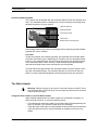
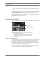
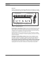
1
Document Finishing System Operating Manual Automatic Stitch-Fold Version Issue 1, November 2011 © Watkiss Automation Limited 2011 All Rights Reserved. Reproduction, adaptation, or translation without prior written permission is prohibited, except as allowed under the copyright laws. Warranty The information contained in this document is subject to change without notice. Watkiss Automation Limited makes no warranty of any kind with regard to this material, including, but not limited to, the implied warranties of merchantability and fitness for a particular purpose. Watkiss Automation Limited shall not be liable for errors contained herein or for incidental or consequential damage in connection with the furnishing, performance or use of this material. Table of Contents 1. Introduction to the Document Finishing System . . . . . . 1 2. Using the Document Finishing System . . . . . . . . . . . . . . 7 Collating Sequentially Printed Sets . . . . . . . . . . . . . . . . . . . . . 7 Normal Collating . . . . . . . . . . . . . . . . . . . . . . . . . . . . . . . . . . . . 9 3. About the Machine . . . . . . . . . . . . . . . . . . . . . . . . . . . . . 11 Control Panel . . . . . . . . . . . . . . . . . . . . . . . . . . . . . . . . . . . . . Friction Feed Bins . . . . . . . . . . . . . . . . . . . . . . . . . . . . . . . . . SlimVAC Suction Feed Bins . . . . . . . . . . . . . . . . . . . . . . . . . . Gathering Station . . . . . . . . . . . . . . . . . . . . . . . . . . . . . . . . . . Automatic Stitch-Fold & Trimmer . . . . . . . . . . . . . . . . . . . . . . The Stitch Heads . . . . . . . . . . . . . . . . . . . . . . . . . . . . . . . . . . Front Outfeed Conveyor . . . . . . . . . . . . . . . . . . . . . . . . . . . . . Joggers . . . . . . . . . . . . . . . . . . . . . . . . . . . . . . . . . . . . . . . . . 11 25 29 35 37 43 50 52 4. Bar Code Reader . . . . . . . . . . . . . . . . . . . . . . . . . . . . . . . 55 Introduction . . . . . . . . . . . . . . . . . . . . . . . . . . . . . . . . . . . . . . Running the Job . . . . . . . . . . . . . . . . . . . . . . . . . . . . . . . . . . . About the Barcode Reader . . . . . . . . . . . . . . . . . . . . . . . . . . . Defining and Printing the Barcode . . . . . . . . . . . . . . . . . . . . . Problem Solving . . . . . . . . . . . . . . . . . . . . . . . . . . . . . . . . . . . 55 56 57 59 63 5. Maintenance . . . . . . . . . . . . . . . . . . . . . . . . . . . . . . . . . . . 65 Service Interval . . . . . . . . . . . . . . . . . . . . . . . . . . . . . . . . . . . 65 Operator Maintenance . . . . . . . . . . . . . . . . . . . . . . . . . . . . . . 65 Operator Maintenance - Automatic Stitch-Fold and Trimmer . 68 . . . continued Watkiss Document Finishing System User Manual (Automatic Stitch-Fold Version) English, Issue 1, November 2011, Watkiss Part No. 960-891 Effective Serial No. WA/VAR/2450 onward Document Finishing System User Manual 6. Problem Solving . . . . . . . . . . . . . . . . . . . . . . . . . . . . . . . 75 Trouble Shooting Chart . . . . . . . . . . . . . . . . . . . . . . . . . . . . . Paper Jams . . . . . . . . . . . . . . . . . . . . . . . . . . . . . . . . . . . . . . Replacing Fuses . . . . . . . . . . . . . . . . . . . . . . . . . . . . . . . . . . Error Messages . . . . . . . . . . . . . . . . . . . . . . . . . . . . . . . . . . . 75 85 86 86 7. User Safety Information . . . . . . . . . . . . . . . . . . . . . . . . . 91 Instructions for safe use . . . . . . . . . . . . . . . . . . . . . . . . . . . . . 91 8. Specifications . . . . . . . . . . . . . . . . . . . . . . . . . . . . . . . . . 93 9. Declaration of Conformity . . . . . . . . . . . . . . . . . . . . . . . 95 Index . . . . . . . . . . . . . . . . . . . . . . . . . . . . . . . . . . . . . . . . . 97 Document Finishing System User Manual CHAPTER 1 Introduction to the Document Finishing System Thank you for choosing the Document Finishing System. About Your Manual This manual explains how to operate the Document Finishing System, correct and solve most error conditions and perform routine maintenance. Operator training will be provided when the machine is installed, however it is recommended that you also take time to read this manual. In this manual the Document Finishing System is referred to as the DFS. Safety Information Safety information is included in “User Safety Information” on page 91. You are advised to read this information before you start to use the Document Finishing System. Installation The installation of your DFS requires specialist knowledge and should therefore only be carried out by a supplier approved engineer. Caution: The DFS must only be plugged into an electrical supply line of the correct voltage and with a proven earth. Any damage caused by failure to do so will not be covered by the warranty. The required machine voltage is shown on the label on the rear of the Document Finishing System and the rear of the Automatic Stitch-Fold. Getting Help We are confident that your DFS will give many years of trouble-free production. If you have any queries or problems, in the first instance please refer to the problem solving section in this book. Should you require further assistance, please contact your supplier. Document Finishing System User Manual 1 1 - Introduction to the Document Finishing System About the Document Finishing System The DFS typically consists of the following components: • A GUI (Graphical User Interface) colour touch-screen that controls the operation of the DFS • Feed bins, that are used to add covers or inserts to booklets where required • A gathering station, that gathers complete sets of pages • An Automatic Stitch-Fold that stitches and folds the sheets into booklets • A trimmer that trims the fore edge of the booklet • An outfeed conveyor that connects to the trimmer • An optional bar code reader • An Automatic Online SpineMaster that post-processes booklets to give them the appearance of perfect binding with the security of a stitched spine. This is an optional module and is documented in a separate operating manual. GUI (graphical user interface) Feed bins Optional bar code reader Gathering station Automatic Spine Master Trimmer Automatic Stitch-Fold Document Finishing System and Automatic Spine Master 2 Document Finishing System User Manual 1 - Introduction to the Document Finishing System GUI (graphical user interface) Feed bins Optional bar code reader Gathering station Outfeed conveyor Trimmer Automatic Stitch-Fold Document Finishing System and outfeed conveyor Document Finishing System User Manual 3 1 - Introduction to the Document Finishing System Switching the Document Finishing System On and Off Mains Input. There are two mains inputs: one on the rear of the tower drive unit and one on the rear of the Automatic Stitch-Fold. Two fuses are fitted next to each of the mains inputs. Mains Input Serial Number Document Finishing System Mains Input Mains ON/OFF Switch Mains Input Serial Number Voltage Indicator Automatic Stitch-Fold Mains Input Mains On/Off Switch. Mains On/Off switches are located on the side of the tower next to the emergency stop button, and alongside the Automatic StitchFold mains input. The mains On/Off switches should be used to turn the system on and off when required. When the system is switched off it retains the control panel settings in memory. Mains ON/OFF Switch Emergency Stop 4 Document Finishing System User Manual 1 - Introduction to the Document Finishing System Important: To maintain the efficiency and prolong the service life of the static elimination equipment, it is important to switch off the tower when it is not being used for a period of hours e.g. overnight. Emergency Stop The emergency stop button should only be used when an immediate stop of the machine is required. Under normal circumstances the machine should be stopped by touching the stop button on the control panel. If the emergency stop button is used, the system will not restart until the button has been released by turning it clockwise. Document Finishing System User Manual 5 1 - Introduction to the Document Finishing System 6 Document Finishing System User Manual CHAPTER 2 Using the Document Finishing System This chapter provides details on how to use the Document Finishing System. For details on the individual modules and how to adjust them, please refer to Chapter 3 on page 11. Collating Sequentially Printed Sets The DFS system can be used to automatically gather sets from a sequentially printed stack of paper. The sheets are held in the gathering station until the set is complete, and it is then released into the Automatic Stitch-Fold and trimmer. Preparation • Press END JOB to end the previous job. • Press INCH to check that there are no sheets remaining in the conveyor. • Clear any remaining sheets from the DFS system. Tip: Load the Default Template to return the control panel to its default factory settings: Touch END JOB Touch LOAD & SAVE Select the Default Template from the list of jobs Touch LOAD If asked, select YES to confirm that you wish to load the Default Template Document Finishing System User Manual 7 2 - Using the Document Finishing System Loading the Bins with Paper Load the sheets so that the centre spread of the book is face up. Centre Spread Face Up Outside Face Down Finishing Sequentially Printed Sheets • Load the bins and switch on, use bin linking if required. • Adjust the feed bin settings to suit the paper type. Inserting a Cover If you wish to insert a separate cover it should be loaded into the lowermost bin with the outside face down. The other sheets are then loaded in the bin(s) directly above. Adjust the Automatic Stitch-Fold and Trimmer • Adjust the Automatic Stitch-Fold and trimmer for the paper size and book thickness, using the GUI control panel. Note: The Automatic Stitch-Fold and Trim contain several axes that are automatically adjusted to suit the job settings. The machine will ‘beep’ twice when the axes have finished adjusting. • Adjust the outfeed conveyor wheel. • Select edge or centre stitching. • Adjust the position of the stitch heads, if necessary. • Set the trimmer conveyor gap. Adjust the Gathering Station • Adjust the gathering station for sheet width. • Adjust for sheet length. • Adjust the air blow if necessary. Bar Code Reader (where fitted) • Adjust the Bar Code Reader as needed. See “Bar Code Reader” on page 55. Starting the Job • Touch NUMBER OF SETS in the BATCH window and input the number of sheets required in each book. • To insert a cover, in the BATCH window, touch INSERTS and set BOTTOM to ON (the NUMBER OF SETS in the BATCH window must be set to 1 or greater) 8 Document Finishing System User Manual 2 - Using the Document Finishing System • In the BASIC window, select PRENUMBER, and set the SETS PER HOUR to AUTO. Test Set. A test set must be run at the start of each job. Touch to run a test set. If PRENUMBER is selected, the test set is counted and the sheet should be left in the gathering station. Tip: To avoid wasting sheets during the test set, the sheets can be diverted out of the front of the gathering station using the manual bypass gate. Note: If PRENUMBER is not selected, the test set is not counted, and the sheet should be removed from the gathering station and replaced in the feed bin. Note: If a cover is being inserted, it is not fed during the test set. The calibration reading for the cover is automatically taken when the job is started. Touch to run the job. Once the machine is running, adjustments may be necessary depending upon the stock in use. The machine can be stopped at any time by touching . Alternatively, to stop the machine when the current batch/set is complete, touch STOP in the BATCH window. Normal Collating Preparation • Press END JOB to end the previous job. • Press INCH to check that there are no sheets remaining in the conveyor. • Clear any remaining sheets from the DFS system. Tip: Load the Default Template to return the control panel to its default factory settings: Touch END JOB Touch LOAD & SAVE Select the Default Template from the list of jobs Touch LOAD If asked, select YES to confirm that you wish to load the Default Template Loading Sequence Load the centre spread of the book face up in the uppermost bin (see below). The other pages should be loaded progressively downwards using as many bins as are required. The cover should be loaded into the lowermost bin with the outside face down. Document Finishing System User Manual 9 2 - Using the Document Finishing System Centre Spread Face Up Outside Face Down Finishing Batch Printed Sheets From the BATCH window, set the NUMBER OF SETS to 1. This will feed one sheet from each active bin, and then open the latch in the gathering station to allow the set to travel into the Automatic Stitch-Fold. Adjust the Automatic Stitch-Fold and Trimmer • Adjust the Automatic Stitch-Fold and trimmer for the paper size and book thickness, using the GUI control panel. Note: The Automatic Stitch-Fold and Trim contain several axes that are automatically adjusted to suit the job settings. The machine will ‘beep’ twice when the axes have finished adjusting. • Adjust the outfeed conveyor wheel. • Select edge or centre stitching. • Adjust the position of the stitch heads, if necessary. • Set the trimmer conveyor gap. Adjust the gathering station • Adjust the gathering station for sheet width. • Adjust for sheet length. • Adjust the air blow if necessary. Starting The Job Touch to run a test set. A test set must be run at the start of each job. Remove the resulting booklet from the outfeed conveyor and check that the sheet sequence is correct. Touch to run the job. Once the machine is running, adjustments may be necessary depending upon the stock in use. The machine can be stopped at any time by touching 10 . Document Finishing System User Manual CHAPTER 3 About the Machine This chapter explains in detail about each of the different modules that make up your Document Finishing System, and how to make adjustments to them. For instructions on using the Document Finishing System for production jobs, please refer to Chapter 2 on page 7. Control Panel Your DFS is fitted with a GUI (Graphical User Interface) control panel. The control panel has an 8.2" colour touch-screen, which offers a user-friendly interface for operators. There are start and stop buttons mounted on the control panel’s frame, these buttons are also repeated on the touch-screen. Start Button Stop Button Touch-screen GUI Control Panel The touch-screen has a ‘power save’ function: if it is not used for a period of time, it automatically dims. After an extended period, it switches off. In either case, touch the screen to return it to normal. Tip: The touch-screen takes two or three minutes to reach full brightness when it is switched on. Document Finishing System User Manual 11 3 - About the Machine The Window System The DFS is controlled by touching buttons on the control panel. The buttons are divided into groups that perform related functions. Each group of buttons has its own ‘window’ which is selected by touching the relevant tab: • • • • • • Load & Save Basic Advanced Feed Batch Finishing Start/Stop Test Set Inch/Pause End Job Help Menu Control Buttons Each window contains a group of related buttons Load & Save Feed Basic Advanced Touch the relevant tab to display each window Batch Finishing Main Window Tabs on the Control Panel ‘Control’ Buttons There are six main ’control’ buttons listed across the top of the screen: START/STOP ~ The button starts the machine. When the machine is running, this button changes to which stops the machine. These are duplicated by the start/stop buttons above the touch screen. 12 Document Finishing System User Manual 3 - About the Machine INCH ~ Touch and hold INCH to turn the conveyor. The conveyor will stop when INCH is released. This is used for clearing any sets remaining in the conveyor after a jam, etc. When the machine is running, this button changes to PAUSE. Touch PAUSE to pause the feed for approximately 5 seconds, the conveyor continues to run. The pause time can be altered on the Machine Options page. END JOB ~ Touch END JOB when you want to set the machine up for a new job, or alter an existing job. When a job is loaded, some of the machine settings cannot be changed, to prevent accidental changes. END JOB unlocks these settings. This only affects settings that change the integrity of the job, e.g. the number of sheets in a set, or the number of sets in a batch. TEST SET ~ When the test set icon is highlighted, the DFS is ready to run a test set. The DFS uses the test set to calibrate the system according to the stock in each bin. The test set is not counted by the counter (except when in prenumber mode). Once the test set is completed and is accepted by starting the machine, the bins and certain functions cannot be changed, to prevent errors and accidental button pushes. To run a test set: • Load the DFS. • Touch the button. • The tower will feed a single sheet from each bin that is switched on and loaded. • If an error occurred during the test set, or the bin loading is changed at this stage, touch to run another test set. • When the test set icon is grey, the machine is ready to run. If either the TEST SET or END JOB button is touched, another test set will need to be run before the job can be restarted: the test set icon will be highlighted. If you are having trouble running a job and false errors are being reported, it may help to run another test set. This can be done at any time to recalibrate the detector system. HELP ~ Touch HELP and then touch any area of the screen to display the help text. Use the ‘up’ and ‘down’ arrows next to the text to scroll up or down the screen. Some sections of help text have a ‘right’ arrow next to them. This indicates that there is more text available, explaining a related function in more detail. Touch the ‘right’ arrow to view this text. A ‘left’ arrow will then also appear: touch this to return to the previous text. Document Finishing System User Manual 13 3 - About the Machine When you are viewing text, you can find out about any of the other tabs that remain on display by touching them. To exit the help text, touch HELP or OK. MENU ~ MENU gives access to settings that do not need to be changed on a day-to-day basis. These settings include: • • • • Change the display language Toggle between metric and imperial measurements Adjust the screen contrast Adjust the pause duration There are several access levels: some of the settings can only be changed by users with an appropriate access code. MIMIC DIAGRAM ~ The mimic diagram of the DFS shown on screen is automatically created, based on how many bins are fitted and what finishing equipment is connected. Various areas on the outline will be highlighted in different colours, according to the operational status of the DFS. Mimic Diagram Counter The feed bin colours mimic the bin indicator lights: • • • • • Steady green: This bin is selected, and is loaded with paper White: This bin is not selected Broken line between bins: These bins are linked Flashing green: This bin is selected, but it has run out of paper Flashing red: This bin has had a double feed, which has caused the Document Finishing System to stop. The error will be explained in a pop-up box • Flashing yellow: This bin has had a miss, which has caused the Document Finishing System to stop. The error will be explained in a pop-up box Automatic Stitch-Fold and Trimmer: • White: The Automatic Stitch-Fold and trimmer are ready for use. • Red: The Automatic Stitch-Fold and trimmer are not ready. This may be caused by an open guard or full trim bin. 14 Document Finishing System User Manual 3 - About the Machine Errors in other modules are indicated in red. C ~ Touching C resets the set counter to 0. SPH ~ SPH shows the actual production speed of the DFS, in sets per hour. The production speed is affected by paper size, online finishing equipment and the job setup. The ‘BASIC’ Window The BASIC window contains settings that regularly need to be altered when setting up a new job. ‘BASIC’ Window. SETS PER HOUR ~ SETS PER HOUR allows the production rate of the DFS to be set. AUTO: Selecting AUTO allows the DFS to run at its maximum production speed according to paper size, online finishing equipment and the job setup. SINGLE SET: Normally there will be more than one set in the conveyor at any one time. Touch SINGLE SET to allow only one set in the conveyor at a time. This minimises the correction required should an error occur. The sets per hour will automatically adjust to achieve this. AIR BLOW ~ AIR BLOW alters the amount of air available for sheet separation in the feed bins. As a general rule, the heavier and larger the sheet, the more air you need. PRESET ~ PRESET is used if an exact number of sets are required. Touch PRESET and enter the number of sets required on the number pad. The counter in the main area of the screen will turn white. When the machine is started the counter will automatically count down to zero and the DFS will then stop. Document Finishing System User Manual 15 3 - About the Machine Touch to restart the machine. The counter will revert to black and will count up to show how many ‘overs’ are produced. The Preset function is ideal for producing a one-off batch. If you wish to produce several identical batches, it is easier to use the Batch function. PRENUMBER ~ PRENUMBER is intended for use when collating pre-numbered carbonless sets. Touching PRENUMBER selects Single Set mode and causes the test set to be counted by the counter. It also prevents the operator from switching linked bins before one bin has emptied. It is possible to switch off Single Set mode once Prenumber is selected. This allows the machine to run faster when using stock that feeds easily. The ‘ADVANCED’ Window The ADVANCED window allows advanced machine settings to be altered. These settings may be altered to optimise the quality and productivity of a job. ‘ADVANCED’ Window. DRIVE SPEED ~ DRIVE SPEED alters the drive speed of the conveyor rollers and therefore the speed at which the sheets exit the DFS. This setting is independent from the SETS PER HOUR setting. SHEET OFFSET ~ SHEET OFFSET shales the sheets as they exit the feed bins. This can assist the neat stacking of thick sheets or large sets. The range of offset is +/- 20mm between each sheet and affects all bins. The default sheet offset is 0: this causes the sheets in a set to enter the gathering base module with their leading edges level. If an offset is required, it is usual for the bottom sheet of the set to lead: select a positive offset. A small offset can make jogging more effective. 16 Document Finishing System User Manual 3 - About the Machine DETECTOR POSITION ~ The sheet detector measures 15.2mm (0.6") from the feed edge of the sheet and then takes a reading. If the edge of a particularly dark or solid area of print is in this area it can cause detection problems. The DETECTOR POSITION can be adjusted so that it looks at a different part of the sheet. This affects all the bins in the DFS. TOLERANCE: Changing TOLERANCE to x2 COARSE allows for more variation in the detector readings. This prevents false errors being reported when there are variations in the paper or ink density. The default setting is x1 NORMAL. The DFS allows for some variation in the paper or ink density, and constantly changes the range of values it will accept by working out an average value for previous sheets. Increasing Tolerance to x2 COARSE will only be necessary where there are larger variations in stock. DOUBLE DETECTION: Under unusual circumstances, e.g. there are large variations in stock, it may be necessary to turn off DOUBLE DETECTION. This affects all the bins in the DFS. Miss feed detection is unaffected. Before switching off double detection, first try setting TOLERANCE to x2 COARSE. FEED CLUTCH ~ FEED CLUTCH adjusts the clutch feed length for all bins during the test set only. Increasing the value will cause the feed wheelsto drive the paper for longer, which can prevent sheets from slipping. The value can be reduced to prevent excessive pre-feeding of the next sheet in the bin. Optimising the clutch feed length for non-standard paper lengths will produce a more accurate test set, which in turn should reduce errors during the job. The default value is 186.2mm (7.35") during the test set, thereafter the feed length is automatically set to suit the paper size. AUTO: Touch AUTO to set the clutch feed length to the default value of 186.2mm (7.35"). Document Finishing System User Manual 17 3 - About the Machine SUCTION HOLD ~ Increasing the SUCTION HOLD value causes the feeder to allow more time to pick up each sheet. If you are using stock that tends to stick together, increasing the suction hold can improve paper pick-up and in some instances, separation. It is possible to reduce the suction hold when using paper that is easy to feed: this will increase the operating speed of the machine. The default setting is 300mS. The ‘FINISHING’ Window The FINISHING window controls the settings for the Automatic Stitch-Fold and trimmer. ‘FINISHING’ Window. PAPER SIZE ~ Touch PAPER SIZE to alter the settings of the Automatic StitchFold and trimmer to suit the input paper size. RE-REF: If you suspect the Automatic Stitch-Fold or trimmer adjustment system is not calibrated correctly, touch RE-REF to re-reference the adjustment axes. The adjustment axes will return to the current settings once this is complete. Periodically the DFS will automatically re-reference the axes during the setup procedure. PAGE DIRECTION: Touching PAGE DIRECTION switches the orientation of the paper between landscape and portrait. This is only possible if the sheet does not exceed the maximum width accepted by the Automatic Stitch-Fold. PRESETS: Select from a choice of standard paper sizes by touching the PRESET window. 18 Document Finishing System User Manual 3 - About the Machine STITCH AND FOLD ~ The position of the stitch and fold can be offset relative to the centre of the paper. STITCH AND FOLD allows this position to be adjusted up to 20mm in either direction, in increments of 0.2mm. STITCH: The STITCH OFF option will produce booklets that are folded, but not stitched. STITCH POSITION: The ON FOLD option produces booklets which are stitched on the fold line. The ON EDGE option produces sets which are edge-stitched and folded. The Stitch Selection Lever on the Automatic Stitch-Fold must be in the centre-stitch position (see p.40). TRIM ~ Touch TRIM to set the finished book size after trimming. When a preset paper size is selected, this distance is automatically adjusted, but can be finetuned. The trim function can also be switched off. PRE STITCH JOGGING ~ The PRE STITCH JOGGING window has options to alter the way sets are jogged prior to stitching. This ensures the finished booklets are as neat as possible. The maximum speed of the Automatic Stitch-Fold will be reduced when any of the Pre Stitch Jogging options are selected. PRE JOG: This provides additional jogging to the bottom of the set, when using heavy or large sheets. The booklet is stopped by the edge-stitch latch and jogged, before it drops to the stitch latch. DOUBLE JOG: This provides additional jogging to the sides of the set, when using heavy or large sheets. The sidelays jog the set twice when it reaches the stitch latch. STITCH DELAY: Increasing the STITCH DELAY value will cause a delay between the set arriving on the stitch latch and it being stitched. This allows more time for the sheets to settle. The default delay is 1mS. PRE FOLD JOGGING ~ The PRE FOLD JOGGING window has options to alter the way sets are jogged prior to folding. This ensures the finished booklets are as neat as possible. SIDE JOG HOLD: When SIDE JOG HOLD is selected, the sidelays hold the set during both stapling and folding without releasing. This is useful if the booklet is not being folded square, however it is essential that the sheet width is set accurately. FOLD DELAY: This can be adjusted to alter the delay between the set arriving on the fold latch and being folded. This is useful if the booklet is not being folded square, and allows more time for the sheets to settle. The default delay is 180mS. The maximum production speed of the Automatic StitchFold will be reduced if the delay is increased. Document Finishing System User Manual 19 3 - About the Machine BOOK THICKNESS ~ The BOOK THICKNESS window alters the gap betweenthe fold rollers of the Auto Stitch-Fold. The thickness of the set is entered on a scale of 1 to 25: this scale represents 1 to 25 sheets of 80gsm paper. The value will need to be adjusted to allow for heavier or lighter stock. The ‘LOAD & SAVE’ Window The LOAD & SAVE window allows job settings to be saved and reloaded at the touch of a button. Each job is given a name, and the jobs are listed on the screen. To select a job, highlight it by either touching it or by using the up and down arrows. ‘LOAD & SAVE’ Window. SAVE ~ Touch SAVE to save the current settings of the DFS. When the onscreen keyboard appears, enter the job name and then touch OK or CLOSE. The new job will appear in the list of saved jobs. This allows the settings to be recalled in the future, which saves set-up time. REPLACE: If an existing job has been loaded and modified, touching REPLACE will replace the old job with the modified version. CANCEL: Touch CANCEL if you do not wish to save a job that you have modi- fied. SAVE NEW: If an existing job has been loaded and modified, touching SAVE NEW will save the modified version as a new job. When the on-screen keyboard appears, enter the new job name and then touch OK or CLOSE. The original job is unchanged. If the job name is not changed before touching OK or CLOSE, the job will be saved with the current name, suffixed by an asterisk. JOB DETAILS ~ Touching JOB DETAILS shows the settings for each saved job. Select the job that you wish to view from the job list and touch JOB DETAILS to see a summary of the job settings. 20 Document Finishing System User Manual 3 - About the Machine LOAD ~ To load a job, select it on the job list using the up and down arrows or by touching it. Touch the LOAD button. You must touch END JOB before loading a job. PADLOCK SYMBOL ~ The padlock symbol is used to lock and unlock saved jobs. Each saved job has a small padlock symbol next to it, to show whether it is locked or not. To lock or unlock a job, select it on the job list and touch the large padlock button. Some padlock symbols may be greyed out. This is because there are several access levels to the system, which can be used to prevent jobs being altered. DELETE ~ To delete a particular job it must be unlocked. Select the job from the job list using the up and down arrows or by touching it. Touch and hold DELETE. A red bar will appear, filling from left to right. Continue to hold until the red bar reaches the right-hand side. VIEW OF JOB LIST ~ VIEW OF JOB LIST alters the order in which saved jobs are listed, either alphabetically or most recent first. There is a line between Factory Template jobs, and other jobs saved by the operator. The Factory Template jobs are always listed first: only the operatorsaved jobs can be reordered. A->Z: To list jobs alphabetically, touch A->Z. BY USE: To list jobs in the order they were last used, touch BY USE. The job that was run most recently will appear at the top of the list. The ‘BATCH’ Window The BATCH window allows sets to be grouped into batches, with an action at the end of each batch (stop, pause, oscillate or insert sheets). ‘BATCH’ Window. Document Finishing System User Manual 21 3 - About the Machine NUMBER OF SETS ~ Touch NUMBER OF SETS to enter the number of sets in each batch. Entering 0 on the keypad will turn the batch mode off. Note: A 'set' is a feed cycle. When making booklets from sequentially printed (i.e. electronically collated) sheets, a 'set' will be a single sheet. In this case, enter the number of sheets in the document. Counts the total number of batches produced Counts the number of sets per batch Counts the total number of sets produced Batch Counter INSERTS ~ INSERTS allows sheets from the top bin and/or bottom bin to be inserted at the beginning or end of each batch. If the inserted sheet is not part of the job, i.e. it is being used purely as a batch separator, it can be fed from either the top or bottom bin. TOP: Select TOP to feed a sheet from the top bin with the first set of each batch. The inserted sheet will be at the bottom of the batch pile, as the backing board for a pad for example. BOTTOM: Select BOTTOM to feed a sheet from the bottom bin with the last set of each batch. The inserted sheet will be at the top of each batch pile, the cover sheet of a pad for example. STOP ~ STOP causes the machine to stop after each batch, and the counter display will flash. Touch the start button to run another batch. If STOP is selected while the machine is part-way through collating a batch, it will stop once it has completed that batch. This allows the operator to interrupt a job at a convenient point. PAUSE / SEPARATE ~ PAUSE / SEPARATE causes the machine to pause for approximately 5 seconds after each batch. The pause icon on the control panel will flash between batches. 22 Document Finishing System User Manual 3 - About the Machine This function will also separate batches on a booklet maker outfeed conveyor. The pause time can be altered on the Machine Options page (touch MENU, MACHINE OPTIONS). RESTART BATCH ~ Touching RESTART BATCH zeros the batch counter, so that you can restart a batch. Note that if the tower is running, this button will interrupt a batch that is partly completed, and a new batch will be started. The ‘FEED’ Window The FEED window contains the Multifeed, Multiset and Mixed Feed options. With these options the tower can be programmed to feed in selective or special sequences. ‘FEED’ Window. MULTIFEED ~ MULTIFEED allows multiple feeds from each bin per set. For example, a Multifeed size of 4 will feed 4 sheets from each bin in turn. Touch MULTIFEED and enter the number required using + or -. Touch O to switch on. Switch off after use. MULTISET ~ MULTISET allows multiple sets to be loaded and counted. For example, a four part set can be loaded three times in a twelve bin tower. When Multiset is switched on, the counter will count three sets per cycle instead of one. Multiset will also automatically divide an odd number of sets into a batch. Using the previous example, if the desired batch size was fifty, the number of sets fed at each cycle (three) would not divide exactly into the total required. In this case Multiset would feed forty eight sets normally and then just two sets on the final cycle to complete the required batch. Document Finishing System User Manual 23 3 - About the Machine Load the job and switch on the bins. Set a batch quantity and action from the BATCH window if required. In the MULTISET window, use + or - to choose how the sets should be split. Touch O to switch on. Switch off after use. MIXED FEED ~ By using MIXED FEED, special feed sequences can be programmed. Each column represents a stage in the collating cycle. Up to twelve stages can be programmed. The tower will complete each stage in turn and then repeat the cycle. Use the left/right arrow keys to navigate to the required stage. Use the up/down arrow keys to navigate to the required feed bin. Touch the 'enter arrow' to switch on. Use the + and - keys to enter the number of feeds in each stage. Touch O to switch on. Switch off after use. BAR CODE ~ When the bar code reader is fitted, this button is visible in the Feed window. See “Bar Code Reader” on page 55. Barcode option in the FEED window 24 Document Finishing System User Manual 3 - About the Machine Friction Feed Bins For operation of SlimVAC bins please refer to “SlimVAC Suction Feed Bins” on page 29. Bin Controls and Indicators Feed bins are numbered from 1 upwards, with the bottom bin being bin 1. Each bin has its own controls immediately alongside it. 2 1 2 3 4 5 6 Key Item Description Function 1 Red light Indicates a double feed (slow flash indicates the bin sensor is ‘overrange’, see p.28) 2 Yellow light Indicates a miss feed 1&2 Red and yellow lights Indicate a feed jam or trailing sheet 3 Red button Bin on/off switch 4 Green light Indicates the bin is switched on Green flashing light Indicates the bin is switched on, but needs loading 5 Grey button Bin linking switch (see p.28) 6 Small lower green light Indicates the bin is linked to the one below Tray Extenders For large sheet sizes (over A4, 8½ x 11") or when running A4 (or 8½ x 11") portrait it will be necessary to fit tray extenders to support the sheets. One B3 (14¼ x 20¼") tray extender is supplied as standard with each Friction bin. Document Finishing System User Manual 25 3 - About the Machine An optional tray extender is available for running A4 portrait (8½ x 11") Watkiss P/No. 251-303. Loading the Bins. Slide the stock into the bin between the sidelays. Push in the sidelays to centralise the paper in the bin and so that they hold the paper securely. Bin Sidelays Switching Bins On & Off. Before a test set is produced, individual bins will automatically switch on and off as they are loaded and unloaded. Bins can also be manually selected by pressing the red button alongside the bin. In addition, loading the Default Template will switch on all loaded bins. Remember that bins cannot be switched on or off when the system is locked (touch END JOB if necessary). Adjustments Adjustments for paper type and/or size include control over the amount of tray pressure and the amount of separator pressure. Separator Pressure. Increasing the separator pressure acts like a brake, making it more difficult for a second sheet of paper to pass the separator pad. Too little separator pressure will result in double feeds, too much will result in miss feeds or damage to the feed edge of the paper. The ideal separator pressure will depend upon the stock in use. Initially set the lever to its mid-position. To increase separation, move the lever downwards one notch at a time, and to decrease separation move the lever upwards one notch at a time. Moving the lever to its highest position disengages the separator. This position is used for the improved feeding of heavy cardstocks. 26 Document Finishing System User Manual 3 - About the Machine Tray Pressure. Increasing the tray pressure gives the feed wheels greater force on the paper; too much will result in double feeds and increases the possibility of scuffing the paper. Tray Pressure Adjustment Separator Pressure Adjustment The ideal pressure will depend upon the stock in use. Always use the least pressure possible. The lever has five positions and is adjusted by gently pushing downwards whilst sliding the lever in or out. The innermost position gives minimum pressure. Initially set the pressure to minimum for small stock. For large sheets (i.e. if tray extenders are used) initially position the lever one notch out. Air Separation. Air directed from the right hand sidelay is used to separate the top sheets of paper in the stack. The overall air level is adjusted if required by altering the AIR BLOW value, in the BASIC window (see p.15). The air level is also adjustable on each individual bin via a tap on the right hand sidelay. The tap on the sidelay controls the air level into the side of the paper stack. The tap has three positions. The default position is 90° to the sidelay which provides 100% air. Moving the lever one notch towards you provides 50% air. Moving the lever towards you so that it is parallel with the sidelay shuts off the air. Air Separation Adjustment Too much air into the side of the stack can cause the paper to skew as it feeds. Any bins that are not being used should have the air tap shut off on the sidelay to preserve overall system air. Remember to open the tap when the bin is next used. Document Finishing System User Manual 27 3 - About the Machine Bin Linking If required, two or more feed bins may be linked to operate as a single bin. When one runs out of stock, the next bin in the linked group will automatically take over. This allows reloading without stopping the machine. Bin linking can only be enabled when the bins are unlocked i.e. when the TEST SET icon is highlighted on the control panel. Press the grey button on the upper bin to link it with the one below. This will be indicated by the small green light. The mimic diagram on the control panel will show a broken line between bins that are linked. By pressing the red bin on/off button it is possible to select which bin in the linked group is active. If the system is locked, pressing the grey button on any bin will indicate which bins are in the same linked group. Sensor Overrange Sensor overrange is indicated after the test set by a slow flashing red light on the bin in question. Particularly heavy or opaque stock may cause the bin sensor to go ‘overrange’. This means that the sheet is too optically dense for the sensor to ‘see’ through it. Double feeds will not be detected but misses, trailing sheets and jams will be detected as normal. 28 Document Finishing System User Manual 3 - About the Machine SlimVAC Suction Feed Bins For operation of Friction bins please refer to “Friction Feed Bins” on page 25. Bin Controls and Indicators Feed bins are numbered from 1 upwards, with the bottom bin being bin 1. Each bin has its own controls immediately alongside it. 2 1 2 3 4 5 6 Key Item Description Function 1 Red light Indicates a double feed (slow flash indicates the bin sensor is ‘overrange’, see p.32) 2 Yellow light Indicates a miss feed 1&2 Red and yellow lights Indicate a feed jam or trailing sheet 3 Red button Bin on/off switch 4 Green light Indicates the bin is switched on Green flashing light Indicates the bin is switched on, but needs loading 5 Grey button Bin linking switch (see p.32) 6 Small lower green light Indicates the bin is linked to the one below. Tray Extenders For large sheet sizes (over A4, 8½ x 11") or when running A4 (or 8½ x 11") portrait it will be necessary to fit tray extenders to support the sheets. One B3 (14¼ x 20¼") tray extender is supplied as standard with each SlimVAC bin. An optional tray extender is available for running A4 portrait (8½ x 11") Watkiss P/No. 251-303. Document Finishing System User Manual 29 3 - About the Machine Rubber Endlays Rubber endlays are used to control the paper stack in the tray. Two different types are supplied with the machine. It is important that the correct endlay is used in the correct orientation for the paper size in use. Do not push the endlay hard up against the edge of the paper stack. Incorrect usage may result in either misfeeds or double feeds. 330-351 B A When the rubber endlay will sit on the tray extender, position it so that ‘A’ is underneath the paper stack. 330-351 A B Step When the rubber endlay will sit on the bar across the front edge of the bin, position it so that ‘B’ is underneath the paper stack and the step is on the bar. 330-446 C When the rubber endlay will sit within the bin itself, use the special endlay 330-446. Position it so that ‘C’ is underneath the paper stack. Loading the Bins Place a full stack of paper between the two sidelays in the base of the tray. Maximum capacity is achieved when the paper is slightly below the top of the sidelays. Slide the sidelays inwards to centralise the paper. Position the rubber endlays on each tray at the end of the paper stack. The endlay should be underneath and just clear of the edge of the paper (by about 1mm, 1/16”). Note: When using the DFS to collate small sheet sizes, make sure the tray loaded sensor is not covered by the rubber endlay. 30 Document Finishing System User Manual 3 - About the Machine The paper tray raises automatically when the system initially starts and thereafter when the tray is loaded. It is therefore important to load a full stack of paper at a time. The tray automatically lowers either when the tray is empty or when is pressed after the machine stops for any reason. Switching Bins On & Off Before a test set is produced, individual bins will automatically switch on and off as they are loaded and unloaded. Bins can also be manually selected by pressing the red button alongside the bin. In addition, loading the Default Template will switch on all loaded bins. Remember that bins cannot be switched on or off when the system is locked (touch END JOB if necessary). Adjustments There are three adjustments to the feed system which allow the feeding of a wide range of papers. Suction Feed Angle Adjustment Sheet Corrugation Adjustment Suction Feeder Sheet Corrugation. The profile of the suction feeder can be adjusted to provide varying amounts of corrugation in the sheet. Greater corrugation gives greater separation; less corrugation gives less separation. Adjustment is via the knob on the right hand side of the suction feeder. The indicator line on the knob shows the degree of adjustment. The knob is infinitely adjustable between the limits of its travel. When the indicator line on the knob is in the fully up position there is no added sheet separation. The fully down position produces maximum separation. In general the heavier the sheet the less added separation is required. The mid position is suitable for most paper types and should be used as a starting point if in doubt for initial running. Document Finishing System User Manual 31 3 - About the Machine Feeder Angle. The angle between the feeder and the paper can be adjusted to allow the feeding of particularly heavy and/or curled stocks. Adjustment is made using the knob on the left hand side of the suction feeder. Turning the knob one stop in either direction has the effect of raising or lowering the outer edge of the feeder. Continuing to turn the knob will alternate between the two positions. The default position is down. Tray Height. The tray height is adjusted via the lever on the SlimVac bin controls. Moving the lever downwards progressively lowers the paper tray. This increases the distance between the top of the paper stack and suction feeder, and also simultaneously adjusts the flow angle of the air separation. The default position for the lever is the mid position which should be suitable for the majority of stock ranges. Tray Height Adjustment Lever Note: When lowering the tray height, the change will only take effect the next time the tray raises (i.e. after reloading or restarting). Bin Linking If required, two or more feed bins may be linked to operate as a single bin. When one runs out of stock, the next bin in the linked group will automatically take over. This allows reloading without stopping the machine. Bin linking can only be enabled when the bins are unlocked i.e. when the TEST SET icon is highlighted on the control panel. Press the grey button on the upper bin to link it with the one below. This will be indicated by the small green light. The DFS mimic diagram on the control panel will show a broken line between bins that are linked. By pressing the red bin on/off button it is possible to select which bin in the linked group is active. If the system is locked, pressing the grey button on any bin will indicate which bins are in the same linked group. Sensor Overrange Sensor overrange is indicated after the test set by a slow flashing red light on the bin in question. Particularly heavy or opaque stock such as a straw board backing sheet may cause the bin sensor to go ‘overrange’. This means that the sheet is too optically dense for the sensor to ‘see’ through it. Double feeds will not be detected but misses, trailing sheets and jams will be detected as normal. 32 Document Finishing System User Manual 3 - About the Machine Difficult Papers Whenever feed difficulties are encountered we recommend that you follow two basic guidelines: • Switch off all the bins except one. This allows you to concentrate fully on the feed of a single bin • Ensure that only one ‘remedy’ is tried at a time. This will make it much easier to identify the solution The following suggested settings are a recommendation only. Paper characteristics vary and therefore any particular stock may require settings different to those shown. Paper Condition Recommended Settings Standard Settings • • • Suction Feeder angled down Tray height in mid-position Sheet corrugation in mid-position Heavy or Rigid Stock Heavy or rigid stock or board may be unable to bend sufficiently to meet the suction feeder in its lower position. • • Document Finishing System User Manual Raising the angle of the suction feeder reduces the feed angle Raise the tray height 33 3 - About the Machine Paper Condition Recommended Settings Stock Curling Down The stock is too close to the feeder for air to get in between the sheets. • • Lowering the tray height will increase the space between the feeder and the sheets If necessary, increase the feeder angle also Stock Curling Up The upward curl means the tray height detector will ‘see’ the paper before it is close enough to the feeder. • Raise the tray height to lift the paper stack closer to the feeder • • Increase sheet corrugation Lower the tray height to increase the distance between the feeder and the paper stack Lightweight Porous Papers The feeder may suck through one sheet and onto the next, resulting in double feeds. 34 Document Finishing System User Manual 3 - About the Machine Gathering Station The gathering station holds the sheets, which have been delivered from the feed bins, until the set is complete. The set is then released into the Automatic Stitch-Fold. Interface Sockets The interface sockets are located on the right underside of the gathering station. There are three sockets in all. Two identical sockets (either one of which is used to connect the Automatic Stitch-Fold) and one smaller socket that is currently not used. Not Used Online Finishing Sheet Length Adjustment Select the correct paper size using the two levers on the front of the DFS (see below). For non-standard paper sizes, use the setting for the next largest standard paper size. A3 A4 A5 Sheet Length Adjustment Document Finishing System User Manual 35 3 - About the Machine Sheet Width Adjustment Insert a few sheets from the job in between the sidelays. Turn the thumbwheel until the marker aligns with the correct point on the scale. Firmly push the sidelays inwards to check the tamper position, they should just touch the paper. Make further adjustment if necessary. Sheet Length Adjustment Static Elimination Bar Gathering Station Air Blow Adjustment Sidelay Sheet Width Adjustment Bypass Gate Interface Sockets (Hidden) Air Blow Adjustment An air jet is used to prevent sheets in the gathering station from curling forwards. This can be adjusted using the air blow adjustment tap on the side of the gathering station. Manual Bypass Gate When the gathering station releases the sheets, they are delivered into the Automatic Stitch-Fold. To bypass the Automatic Stitch-Fold, pull out the manual bypass gate and the sheets will be delivered out of the front of the gathering station, above the Automatic Stitch-Fold. This is useful to avoid wasting sheets during the test set. Note: The manual bypass gate only works when the DFS is already running. Start the machine first, and then pull it out. 36 Document Finishing System User Manual 3 - About the Machine Automatic Stitch-Fold & Trimmer The Automatic Stitch-Fold and Trimmer units stitch, fold and trim the printed sheets to form a booklet. Finished booklets are delivered onto the outfeed conveyor, or into the optional SpineMaster. The Automatic Stitch-Fold fits underneath the gathering station. It is wheelmounted and can be moved in and out when required. Starting and Stopping the Automatic Stitch-Fold and Trimmer The Automatic Stitch-Fold and Trimmer units will automatically start and stop when required. When the Document Finishing System stops, there is a delay of approximately 5 seconds before the Automatic Stitch-Fold shuts down. For an immediate stop, either press the emergency stop button on the tower or open one of the safety guards. The Automatic Stitch-Fold can also be started by manually feeding a set into the unit. The unit will then automatically stop after approximately 10 seconds. Moving the Automatic Stitch-Fold and Trimmer The Automatic Stitch-Fold and Trimmer units are castor mounted so that they can be wheeled underneath the tower. Press the motor transport switch to move the units in and out. An automatic cut-off switch acts when the units are fully docked under the tower. ASF Interface Cable Motor Transport Switch Disengaging the Motorised Transport System. Under normal circumstances the wheels on the Automatic Stitch-Fold are locked to prevent unwanted movement, and the unit can only be moved using the motorised system. To release this lock in order to move the unit manually, it is necessary to unscrew the wheel lock knob which is located inside the unit, underneath the motor transport switch. Turn the wheel lock knob anti-clockwise until the lock disengages. The Document Finishing System User Manual 37 3 - About the Machine Automatic Stitch-Fold unit will then move freely when pushed. Remember to reengage the wheel lock by turning the knob fully clockwise when in position. Wheel Lock Knob Separating the Trimmer from the Automatic Stitch-Fold • Use the motor transport switch to drive the Automatic Stitch-Fold and Trimmer clear of the tower base unit. • Switch off the Automatic Stitch-Fold. Disconnect the power. • Raise the Lid on the Automatic Stitch-Fold. Raise the lid on the Trimmer. • Disconnect the power and data cables between the two machines. • On the docking bracket, which holds the two machines together, there is a safety interlock. Loosen the orange hand screw. Slide the interlock bar towards the centre of the machine. Tighten the handscrew to secure the interlock bar in this position. • Lift the docking bracket so it clears the locating bar in the Trimmer infeed. • Push the Trimmer away from the Automatic Stitch-Fold. 38 Document Finishing System User Manual 3 - About the Machine Docking Bracket on the Conveyor Outfeed of the Stitch-fold Locating bar in the Trimmer Infeed Adjustment for Paper Size Adjustment for paper size is made on the GUI (Graphical User Interface). See “The ‘FINISHING’ Window” on page 18. • Touch FINISHING to display and adjust the Automatic Stitch-Fold and Trimmer settings • Touch PAPER SIZE, PRESETS and select a standard sheet size - A3, A4 or A5 (11x17", 8.5x11" or 5.5x8.5") • Choose PORTRAIT or LANDSCAPE in the PAPER SIZE, PAGE DIRECTION window • For non-standard paper sizes, touch PAPER SIZE and then use the ‘+’ and ‘-’ keys to set the size • Touch BOOK THICKNESS and select a value to suit the book thickness Axes Calibration. Periodically the Automatic Stitch-Fold and Trimmer will automatically recalibrate the axes during the setup procedure. If you suspect the adjustment system is not calibrated correctly, touch RE-REF in the PAPER SIZE window to manually recalibrate the stitch-fold and trimmer adjustment axes. After recalibration, the adjustment axes will return to the current settings. Document Finishing System User Manual 39 3 - About the Machine Select Edge or Centre Stitching Edge or centre stitching is selected using the ‘side or centre stitch selection lever’. Side or centre stitch selection lever For Centre Stitching. Lift up, slide out and lower. For edge stitching. Lift up, slide in and lower. This will also automatically switch off the fold and trim actions. The maximum sheet length that can be side stitched is 340mm, 13.3". For Edge Stitching and then Folding. Select centre stitching, NOT edge stitching - lift up, slide out and lower. Then set STITCH POSITION to ON EDGE from the STITCH AND FOLD window. This will automatically switch off the trimmer action. The only limitation to this is that the distance from the stitched edge to the fold must be at least half the length of the paper. Adjust the Edge Stitch Drive Wheel This procedure is only required when edge stitching. Jockey Wheel Catch Side Stitch Drive Wheel Lever 40 Document Finishing System User Manual 3 - About the Machine The side stitch drive wheel is located between the stitch heads. Unhook the jockey wheel catch and push in the drive mechanism lever (identified by an orange dot), so that the jockey wheel and drive wheel contact. This improves feeding for side/corner stitching by providing a more positive drive. Ensure the catch is hooked on the screw and the drive mechanism lever is out for centre stitching. When edge stitching heavier papers, the optional Edge Stitch Drive kit, Part No. 914-512, may be required. Adjust the Stitch Heads If required, adjust the position of the stitch heads (see p.43). This is not normally necessary because the stitch-fold is centre referenced. Adjust the Outfeed Conveyor Slide the large payout wheels up or down their mounting rail so that they are just nipping the spine of the book when it is released from the rollers. Payout Wheels Set the Trimmer Conveyor Gap The trimmer conveyor gap has two positions, open or closed, and is set using the conveyor gap adjustment bar. The normal setting is open. If a thin book is bouncing against the trimmer stop and is therefore trimmed out of square, close the gap. If a thick book is either being scuffed, or is jamming on entry into the trimmer, open the gap. For very thick, narrow booklets (eg. folding A4 paper landscape), the conveyor gap can be opened further using an optional aid. • Part No. 914-541, ATR Thick Book Setting Gauge Document Finishing System User Manual 41 3 - About the Machine Open Closed Conveyor Gap Adjustment Bar Check the Adjustments To check that all the adjustments are correct: Wheel the Automatic Stitch-Fold and Trimmer out from under the tower using the motor transport switch. Manually feed a few sheets into the Automatic Stitch-Fold and check the resulting booklet. Return the Automatic Stitch-Fold and Trimmer under the tower. Fine Tuning the Fold Position Occasionally paper characteristics may cause the stitch to be marginally off the fold. The Automatic Stitch-Fold can be fine tuned to compensate for this using the fine tuning control. Fine Tuning for Fold Position Trimmer Offcut Bin The trimmer offcuts are delivered into the trimmer offcut bin. Remember to empty this periodically. If it becomes over full, the DFS will stop and the error message Trim bin full is displayed. 42 Document Finishing System User Manual 3 - About the Machine Producing Small Booklets The Trimmer can be docked with the Automatic Stitch-Fold in two different positions. The standard position is designed to prevent trimmings from being transported through the conveyor system. Trimmer Interlock Docking Bracket Front Fixing Holes Hand screw, fitted through rear fixing hole The docking bracket only needs to be adjusted when producing small booklets (typically A5->A6 or smaller). Procedure To alter the position of the docking bracket, first separate the Automatic StitchFold from the Trimmer (see ‘Separating the Trimmer from the Automatic StitchFold’ on p.38). Undo both the orange hand screws that fix the docking bracket to the Automatic Stitch-Fold’s conveyor. Slide the docking bracket rearward, and refit the orange hand screws through the front fixing holes. This will reduce the gap between the Automatic Stitch-Fold and Trimmer when they are connected together. If the docking bracket is not moved in this way, there is a chance that small booklets could drop between the two machines. The Stitch Heads Warning: Before carrying out any work on the stitch heads you MUST move the Automatic Stitch-Fold unit away from the tower and disconnect it from the mains electricity supply. Using the Hand Crank to Cycle the Stitch Heads When making adjustments to the stitch heads it is sometimes necessary, for safety and convenience, to cycle the heads by hand. • First release the solenoid by sliding your finger behind it and depressing the lever on the back (you will hear it click when it is released). • Insert the hand crank (which is stored inside the stitch-fold unit) into the hand crank access hole and turn it anti-clockwise to complete one cycle of the heads. Document Finishing System User Manual 43 3 - About the Machine • It is necessary to release the solenoid at the beginning of each cycle. Infeed Guide Hand Crank Solenoid Hand Crank Access Hole Caution: Avoid damaging your stitch heads by following these rules: 1. Never drive one stitch on top of another. 2. Never operate the stitcher with wire feeding without paper between the clincher and formers. Adjusting the Position of the Stitch Heads Because the system is centre referenced, the stitch head position will rarely need adjusting. In the majority of cases a stitch pitch of 130mm (5") will be suitable for both A4 and A5 (or US 8½ x 11" and 5½ x 8½") booklets. Ideally the stitch pitch should be set between 65 and 190mm (2¾ to 7¾") so that the heads line up with the cutouts in the fold blade. 44 Document Finishing System User Manual 3 - About the Machine Position the Stitch Heads Open the perspex safety guard on top of the stitch-fold unit and then open the stitch-fold unit itself. Drive Lug Stitch Head Clamp Infeed Guide Hand Nut Scale For each stitch head, release the stitch head clamp by turning it anti-clockwise. Slide the stitch head along its mounting to the required position (taking note of the scale for stitch pitch) and re-tighten the clamp. Ensure that the drive lug is also moved so that it is central on the stitch head. Note: Do not place the stitch heads over the bottom of the infeed sidelay. Sensors prevent the stitch-fold from stitching if this happens in order to prevent damage to both the head and the sidelay. An LED on each sensor is illuminated when this occurs and the message Cannot start: sidelay under stitch head appears on the touch-screen. To place the stitch heads in their widest position, the two infeed guides will have to be moved. Undo the orange hand nut and refit the guides in between the stitch heads. Document Finishing System User Manual 45 3 - About the Machine Align the Clinchers When aligning the clinchers, it sometimes helps to lower the staple driver to make alignment easier and more accurate. Remove the cut staple wire from the stitch head. Use the hand crank to lower the staple driver. Bender Bar lowered Clincher Clincher Fixing Screws For each head, release the clincher by loosening the two clincher fixing screws. Slide the clincher along until it aligns with the stitch head. Retighten the fixing screws and use the hand crank to complete the stitch head cycle before closing the stitch-fold unit. Visually check that there is no staple wire stuck in the clinchers or stitch heads. Wiring the Stitch Heads The stitch heads use 0.53mm (25 gauge) round electro-galvanised steel wire on 2.5kg (5lb) spools. These are available from Watkiss (P/N 812-001) or from your local supplier. Install the Wire Spool Open the perspex safety guard on the top of the Automatic Stitch-Fold unit. The wire spools are mounted on a split bar, half of which swings upwards to allow access. For each spool, remove the retaining clip and large disc, and then remove the empty spool. Ensure that the remaining spring, bushes and disc do 46 Document Finishing System User Manual 3 - About the Machine not fall off. Slide the new wire spool onto the stud with the wire feeding over and up towards the wire guide spring. Replace the large disc and retaining clip. A B C D E F Spool Mounting Bar Split Pin Bush Spring Coil Retainer Spool Retainer Spool Note: Hold the wire taut at all times and do not release it until it has been threaded through the wire guides and wire straighteners. If necessary, remove any loose or tangled wire before you begin. This is essential to prevent de-spooling and tangling. Threading the Stitch Heads Note: When a spool of wire has run out, there will be a small amount of wire left in the middle wire tube. This MUST be removed before a new spool can be threaded. To do this, unclip the middle wire tube from the stitch head. Remove the wire then replace the middle wire tube, ensuring that it is correctly located. Remove the end of the wire from the hole in the outer edge of the spool and thread it through the wire guide spring and through the two wire guides. Follow the sequence shown in the illustrations below: Document Finishing System User Manual 47 3 - About the Machine Pass wire between Oiler Felts Insert wire into Anti Back-up Unit Tension Pawl (anti back-up unit) Loosen to allow thread to pass Upper Wire Tube Turn to disengage Small and Large Feed Gears Threading the Head - Stage 1 Turn to engage Small and Large Feed Gears Guide Wire between the Small and Large Feed Gears Threading the Head - Stage 2 Cycle the heads to cut the wire to the correct length. 48 Document Finishing System User Manual 3 - About the Machine It is important to ensure the stitch wire is straight, particularly if using wire not supplied by Watkiss. Wire straightness is preset at the factory. To check the straightness of the wire, slide the wire holder retaining spring over to the side and remove the wire holder assembly from the stitcher head. Manually crank the stitch head and observe the wire exiting the cutter box assembly. The wire should have a slight upward curve. Wire Guide Spring Wire Oiler Felts Tension Pawl Upper Wire Tube Feed Release Handle Small Feed Gear Large Feed Gear Middle Wire Tube Wire Holder Retaining Spring Wire Holder Assembly Cutter Box Assembly Replace the wire holder and re-engage the wire holder retaining spring. Manually crank the heads over to cut the excess wire off. Testing the Stitch Heads After re-wiring the stitch heads, they should be tested. Slide a few sheets of paper between the heads and the clinchers and then use the hand crank to cycle the heads. Check for a correctly formed stitch and if necessary make adjustments as detailed in the trouble shooting chart. Document Finishing System User Manual 49 3 - About the Machine Front Outfeed Conveyor The front outfeed conveyor is an optional module. It facilitates the delivery of sets from the gathering station into either a straight jogger or an X-jogger. Tie Bar Front Outfeed Paper Guide X-Jogger Attaching the Front Outfeed Conveyor. When attaching the front outfeed conveyor, ensure that you slide it into the small gap between the tower base and the gathering area. This is to support the rear of the outfeed. Gap Rear of Outfeed Once in place, clip the locating hooks over the tie bar. Tie Bar Locating Hooks Caution. Before letting go of the front outfeed conveyor, ensure that the rear end is being supported, if not it will swing down. 50 Document Finishing System User Manual 3 - About the Machine Attach the outfeed earth wire to the connector on the side of the base. Paper Guide Earth Wire Connector Paper Guides. Clip a paper guide onto the tie bar. There are two paper guides provided with the front outfeed (short and standard). The choice of which guide to use is dependent upon paper size and orientation. The guide should be positioned to control the set as it is delivered into the jogger. Caution. When the DFS is to be used with an Automatic Stitch-Fold, the front outfeed conveyor must be removed first. Document Finishing System User Manual 51 3 - About the Machine Joggers Two types of jogger are available as optional modules. The X-Jogger straight or offset stacks whilst the Straight Jogger is used when set separation is not required. If a jogger is to be used, the front outfeed conveyor must be fitted (see p.50) X-Jogger Setting Up the Jogger. Position the X-Jogger under the tower, so that the back edge of the stack is level with the front outfeed, as shown. Connect the jogger to the mains supply and switch on. The X-Jogger with A3 (11 x 17”) Paper Plug the jogger into the socket on the underside of the floor base via the interconnection cable. The cable will only fit in to one of the sockets. Take a few sheets of the stock to be collated and place them in the stacker offset by 20°. Use the hand wheel to adjust the sidelays to suit the width of the stack. Adjust the bottom sidelay so that the middle of the sheet is over the middle of the stacker tray. You can check this by folding a sheet in half (as dotted line in photo) and checking that the fold on the left and right edge is equal distances (’X’) above and below the angle in the sidelays. Paper Guide X X Width Adjustment Support Post Bottom Sidelay Adjustment The X-Jogger with A4 (8½ x 11") Paper Adjust the position of the support posts by twisting anti-clockwise to release, sliding to about 5mm (¼") from the edge of the stack and then re-tightening. 52 Document Finishing System User Manual 3 - About the Machine Adjust the position of the X-Jogger itself, moving it further in or out so that the paper falls neatly into the receiving area. Select OSCILLATE in either the BASIC or BATCH menu (if required) from the control panel menu and run a test set. If needed, fine-adjust the position of the sidelays and support posts to achieve a neat stack. Jogging Adjustment. If necessary, adjust the amount of vibration via the knob on the top of the motor housing (just above the mains On/Off switch). Use the minimum amount of vibration that will successfully jog the stack. Straight Jogger Setting up the Jogger. Place the Straight Jogger in a central position under the tower. Ensure the local control switch is in the off position (green strip not visible). Connect the jogger to the mains supply and turn on the red mains on/off switch. Jogger ‘full’ Sensor Mains ON/OFF Switch Local Control Switch Jogging Adjustment Mains Input Height Adjustment Release Lever Plug the jogger into the socket on the underside of the floor base via the interconnection cable. The cable will only fit in one of the sockets. Run a test set and if necessary, adjust the position of the jogger. Move it further in or out so that the paper falls neatly into the receiving area. A sideways positional adjustment may also be necessary depending on the size of the paper and type of stock. The height of the jogger can be adjusted by releasing the height adjustment release lever. Jogging Adjustment. If necessary, adjust the amount of vibration via the knob on the side of the jogger (as shown above). Use the minimum amount of vibration that will successfully jog the stack. Document Finishing System User Manual 53 3 - About the Machine 54 Document Finishing System User Manual CHAPTER 4 Bar Code Reader Introduction The optional barcode reader module fully integrates into the control system of the DFS. It is configured through the GUI colour touch-screen user interface. Where verifiable integrity is needed, the barcode reader provides multi-level security verification at sheet, set and job level. It can also control the insertion of covers and multiple additional sheets for customized sets. You can configure the system to interpret the barcode characters as required, and save the configurations in easy recall job memories. This means that every sheet can be guaranteed accurate; and every set or document can be customized. It extends variable data beyond the printer to the finisher; with the potential for each set or document to include a different combination of additional inserted sheets. For security verification, elements include job, document and sheet identifiers, a sheet counter and sequence check. Controls for sheet feeding and insertion include insert and specified feed and read commands. Document Finishing System User Manual 55 4 - Bar Code Reader Running the Job Complete setting up procedures for your DFS are included in the Operating Manual provided with the machine. Preparation • Press END JOB to end the previous job. • Press INCH to check that there are no sheets remaining in the conveyor. • Clear any remaining sheets from the DFS. Tip: Load the Default Template to return the control panel to its default factory settings: Touch END JOB Touch LOAD & SAVE Select the Default Template from the list of jobs Touch LOAD If asked, select YES to confirm that you wish to load the Default Template • Your print supplier will provide information regarding the barcode definition and the bin loading sequence if applicable. Ensure you have this information before starting the job. Loading the Bins with Paper • Load the sheets so that the barcode is on the underside of the sheets. When booklet making, the centre spread of the book is face up. • If all sheets are to be fed from one stack, the lower-most bins of the tower should be used. Bin linking may be used if required, in which case load the bins so that the uppermost bin of the group feeds first. • If the job includes several different sheets - for example a cover or variable inserts, your print supplier will provide instructions for the bin loading sequence together with the barcode definition. • Identify which is the ‘master bin’. This is the feed bin which contains the first sheet of the set and is used for the test set. • Switch off all bins except the master bin. • Adjust the feed bins, gathering station and booklet maker to suit the paper size and type. Starting the Job Touch BARCODE in the FEED window. Input the number of barcode characters and the barcode definition. Switch on the barcode by touching the Barcode On/Off selection icon. Close the FEED window and check that the barcode definition is displayed on the screen. Check that the correct master bin number displayed. • Touch to run a test set. Check that only a single sheet has fed, and that it has fed from the correct bin. • • • • Note: Only the master bin will feed during the test set. The calibration reading for other bins is automatically taken when they first feed a sheet. 56 Document Finishing System User Manual 4 - Bar Code Reader • Leave the test set sheet in the gathering station and touch ning. to continue run- The machine can be stopped by touching . The current set will be completed and then the machine will stop. If an immediate stop is required, press the Emergency Stop button. Barcode definitions and other job parameters can be saved and recalled in the LOAD & SAVE window in the normal way. About the Barcode Reader The barcode reader scans the barcode as the sheet enters the gathering area. Barcode Reader Adjustment thumbscrew Indicator lights. The barcode reader has 4 indicator lights: • • • • Device Ready: always on. Result: flashes when a barcode is read satisfactorily. Laser On: illuminated when the barcode is reading. Data: unused. Positioning the Barcode Reader The reader will scan across the full width of the sheet. This can be observed by watching the red light projected onto the sheets when the reader is scanning. The position of the barcode reader can be adjusted along the width of the mounting bar. For optimum performance, it should be positioned approximately inline with the position of the barcode on the sheet. Loosen the thumbscrew on the underneath of the barcode reader and slide it into the required position, then retighten the thumbscrew. Document Finishing System User Manual 57 4 - Bar Code Reader Barcode Window on the Control Panel The barcode definition is set up via the BARCODE option in the FEED window. Barcode option in the FEED window Configuring the barcode. • Select the number of characters contained in the barcode. • Define each character in the barcode, using the up/down arrows to select the barcode element, and the left/right arrows to move from one character to the next. Number of barcode characters Barcode definition Barcode ON/OFF selection Definition navigation and selection DOUBLE SCAN ~ By default, the barcode reader requires two identical scans to recognise the barcode. With small barcodes at high speed, there may not be time to complete two scans. In this case, either lower the drive speed, or touch DOUBLE SCAN so that OFF is displayed. In this mode, only a single scan is required to recognise the barcode. Double scan should be ON unless it is not possible to obtain satisfactory results, in which case it can be switched OFF. 58 Document Finishing System User Manual 4 - Bar Code Reader During the job. During the job, the GUI displays the barcode definition, the result of the code last read and the next required code (where applicable). Master bin number Barcode definition Results display & Required next result Defining and Printing the Barcode The barcode can be generated and printed using barcode generation software of your choice, provided it complies with the parameters on the following pages. Instructions for Finishing The following information is needed by the DFS operator in order to finish the job: • The Barcode elements to be programmed into the GUI. For example, ZZSS or DDDDFSS. • The bin loading sequence. This information is needed if the barcode elements include R (read and feed from a specified bin) or I (insert). Document Finishing System User Manual 59 4 - Bar Code Reader Barcode Specification Minimum Height 3.5mm preferred, 2mm possible Length 2 - 22 characters Type Code 128 is the preferred format. Code 39 may be used. Resolution The print should have a minimum resolution of 0.3mm. This applies to the line width and line separation. Colour Black barcode on a white background is recommended. Other colour combinations should be tested for reliable performance prior to proceeding. Position The barcode reads across the width of the sheet (i.e. a picket fence barcode). The barcode can be positioned anywhere across the width of the feed edge of the sheet. Minimum distance from feed edge of sheet: 2mm. Minimum distance from trailing edge of sheet: 130mm. When booklet making, this means that the barcode can be positioned in the trim margin, so that it is trimmed off the finished booklet. Alternatively it can be positioned in the centre of the sheet, so that it is in the gutter (spine) of the finished booklet. The barcode cannot be printed in the grey portions of the sheet: FEED DIRECTION 130mm Orientation 2mm When the printed sheets are loaded into the DFS feed bin, the barcode will be on the underside of the sheet. When booklet making, the barcode should therefore be printed on the outside face of each sheet - i.e. facing the cover of the booklet and on the outside of the cover. 60 Document Finishing System User Manual 4 - Bar Code Reader Barcode Elements Barcode elements can be used in any sequence and an element can be as many numeric characters as required. It is not necessary for the barcode to include all the elements listed below. Barcode Elements - Undefined This character of the barcode is not used. J Job ID This ID is a static job identification code and is fixed at the start of a Job. All sheets of the Job must have the same ID. Q seQuential This is a sequential sheet identification number running through whole job. This may count up or down; it is initialised at the start of the job. D Document ID This is a document/set identification code. All sheets of the document/ set must have the same ID. This is initialised on the first sheet of a set. Z siZe of set This is the number of sheets in the set. It is used in conjunction with the Sheet counter. S Sheet counter This is the sheet number within the set. If used together with siZe, no First or Last mark is needed. It may count up or down. If siZe is not used, either a First or Last mark must be used. If a First marker is used, the counter must count down. If a Last marker is used, the counter must count up. F First sheet of the set This marks the first sheet of a set and must be used in conjunction with the Sheet counter (counting downwards). L Last sheet of the set This marks the last sheet of a set. It is not necessary to use a Last marker if both S and Z are used. T sTop Terminates operation of the machine after this sheet. Document Finishing System User Manual 61 4 - Bar Code Reader Barcode Elements I Insert Inserts a sheet from the relevant feeder. e.g. If I = 3, a sheet will be inserted from bin 3. This character can be used as many times as required within the barcode to give multiple inserts. R Read Feed a sheet and Read the Barcode from a specified feeder. e.g. If R=3 the next feed will be from Bin 3 and the Barcode on that sheet will be used to control the subsequent actions. NB. If R=0 then subsequent feed and control will pass back to the master (test set) bin Examples Basic Set Control Size of set (12) Sheet counter, counting down (12, 11, 10 etc.) ZZ SS 12 12 12 11 12 10 12 09 etc. Basic Set Control with sheet insertion Size of set (3) Sheet counter, counting down (3, 2, 1) Insert from specified bin Insert from specified bin Z S I I 3 3 0 0 3 2 0 0 3 1 3 4 Insert from bins 3 and 4 62 Document Finishing System User Manual 4 - Bar Code Reader Document Security Document ID - changes for each set First sheet marker Sheet counter, counting down DDDD F SS Document Security Job ID - the same for all sets in the job Document ID - changes for each set First sheet marker Sheet counter, counting down Stop marker JJJ DDDD F SS T Problem Solving Error Causes Errors may occur: • • • • • if the barcode is printed incorrectly if the barcode is defined incorrectly during set-up if the job is loaded incorrectly if the wrong master bin is selected if the feed bin(s) have a feed error Error Reporting If an error occurs, an error message is displayed on the GUI screen and the faulty character in the definition and result lines are highlighted in red, showing the error. Barcode error indication Document Finishing System User Manual 63 4 - Bar Code Reader Barcode Error ~ The barcode reader failed to read the barcode: • Check that the barcode is valid. • Check the reader alignment. See “Positioning the Barcode Reader” on page 57. • Check the barcode setup (length and format). • Check the drive speed .v. barcode height. See “DOUBLE SCAN” on page 58. • Retry the last sheet. The Barcode Error message may be combined with other information, for example Barcode Error Bin: # miss indicating that bin # has missed a feed. Barcode Setup Error ~ The Barcode reader has not responded as expected. This usually means that the barcode reader is not communicating with the control system. Touch END JOB, open the BARCODE window and turn the barcode off and then on again. If the error persists, switch the entire finishing system off and on again at the Mains On/Off switch before retrying. Error Recovery If the wrong master bin is selected. Touch END JOB and turn off the barcode in the BARCODE window. Switch off all bins except the master bin using the bin on/off switches beside the bins. Switch the Barcode back on again in the BARCODE window. The correct master bin should now be selected. This is indicated on the GUI (see p.59). Replace any error sheets in the feed bin(s) and touch to restart the machine. If a missfeed has occurred. Touch to restart the machine. The sheet should feed and the set will be correct. If this error recurs, refer to ‘Miss Feeds’ in the Problem Solving section of your finishing system operating manual. If a double feed has occurred. Remove the double sheets from the gathering station and replace them in the feed bin, in the correct sequence. Touch to restart the machine. If this error recurs, refer to ‘Double feeds’ in the Problem Solving section of your finishing system operating manual. To restart the set. Remove all error sheets from the gathering station and/or feed bin(s). Ensure that the sheets in the feed bins are in the correct sequence. Touch END JOB and open the BARCODE window. Turn the barcode off and then on again, close the BARCODE window. Touch to restart the machine. 64 Document Finishing System User Manual CHAPTER 5 Maintenance Service Interval It is recommended that your DFS is serviced by an approved Watkiss engineer every 1,000 operating hours. Please contact your supplier. This chapter covers all routine adjustment and maintenance procedures that can be carried out by an operator. Some of these procedures require a degree of technical competence, and you may prefer for these to be undertaken by your Watkiss engineer. Operator Maintenance As with all machinery, your DFS will benefit from periodic cleaning of general accumulations of paper dust, ink etc. Document Finishing System User Manual 65 5 - Maintenance Cleaning Materials The DFS should only be cleaned with a cloth moistened with soap and water or with alcohol (isopropanol). Important. Do not use any of the following chemicals to clean the separators, feed wheels or conveyor wheels: Cleaners based on esters and ketones, e.g ethyl or butyl acetate esters or methyl ketone (MEK). Aliphatic solvents, e.g. petrol or SBP1. Aromatic solvents/cleaners, e.g. toluene xylene, napthas. Chlorinated solvents/cleaners, e.g. trichloroethylene, perchloroethylene genclenes. All of these chemicals will damage the separators, feed wheels and conveyor wheels to a varying degree resulting in poor performance and premature failure. Touch Screen The touch screen should only be cleaned with a clean, dry cloth. Abrasive materials and chemicals should never be used to clean the screen. Light pressure with a suitable cloth should be sufficient to remove fingerprints. Do not use excessive force. Static Elimination Bar The static elimination bar is located in the gathering station. Caution: Disconnect the machine from the mains electricity supply before cleaning the static elimination bar. The pin side of the bar should be cleaned regularly using a small brush such as a toothbrush. This is vital to the effectiveness and life expectancy of the static elimination equipment. Static Elimination Bar 66 Document Finishing System User Manual 5 - Maintenance Friction Feed Bins Paper Separators (P/No 909-485). There is one paper separator located in the centre of each friction feed bin. It slots into the aluminium pick-up manifold immediately beneath the central feed wheel. They should be cleaned if dirty and replaced when worn. The replacement interval will depend upon the usage level and the type of papers used. Paper Separator • Remove the feed wheel shaft by pushing it to the left against the spring pressure and lifting the right end clear • Locate the separator and lift it out vertically • Clean or replace the separator as required. When cleaning the separator use only soap and water or alcohol (isopropanol). Refit the separator and ensure that it seats firmly in the correct position • Refit the feed wheel shaft Feed Wheels (P/No. 330-301). The friction feed bins are fitted with three feed wheels (B) mounted on a shaft. They should be cleaned if dirty and replaced when worn. The replacement interval will depend upon the usage level and the type of papers used. B • Remove the feed wheel shaft by pushing it to the left against the spring pressure and lifting the right end clear. Clean the wheels using only soap and water or alcohol (isopropanol) • If the wheels need to be replaced, grasp the shaft firmly and slide off each wheel (this will be eased by wetting the shaft slightly) • Ensure the shaft is clean, and slide on each new wheel, ensuring that the wheels align with the correct marks on the shaft. The standard position for the wheels is shown below Document Finishing System User Manual 67 5 - Maintenance • Replace the shaft • Select CLEANING in the MENU, USER SETTINGS window and press the red button on the bin controls to turn the feed wheel shaft. Visually check that each wheel runs true. To straighten a wheel, gently hold a flat edge against the wheel whilst it turns Operator Maintenance - Automatic Stitch-Fold and Trimmer Cleaning Build up of set-off powder, ink, toner or general dust will gradually impair the performance of your Automatic Stitch-Fold and Trimmer. Optimum performance will be obtained by keeping the machine clean. Fold Roller and Conveyors Build up of set-off powder or ink on the fold rollers and conveyor belts will eventually cause slippage or ink transfer. Use the hand crank to turn them and clean with a cloth dampened with soap and water or alcohol (isopropanol). Caution: Access to the trimmer hand crank and clutch requires the side cover and the black cover under the blade to be removed. For safety reasons this should only be conducted by authorised personnel. 68 Document Finishing System User Manual 5 - Maintenance Edge Stitch Deflector The surface of the deflector should be cleaned periodically using anti-static polish. Edge Stitch Deflector Fold Roller Stitch Heads The stitch heads should be fully serviced every one million cycles. Please contact your Watkiss supplier or the manufacturer for further details. Stitch Head Lubrication Caution: Failure to lubricate the stitch heads according to these schedules may result in damage to the stitch heads and invalidate your warranty. Using any standard SAE10 (3 in 1) oil, lubricate using one drop of oil in each point, shown in the illustration below. Weekly. Stitch heads that are in constant operation should be removed and lubricated weekly or once every 250,000 stitches. Every Third Spool Change. Stitch heads that are operated periodically should be removed and lubricated every 120,000 stitches or every third wire spool change, which ever comes first. Monthly. If the unit has low usage, it should be lubricated once a month. Document Finishing System User Manual 69 5 - Maintenance Wire oiler felts Top of the bonnet on either side of the feed slide In the oil cup of the small feed gear shaft assembly securing the small feed gear to the feed lever Stitch Head Lubrication Sharpen the Trimmer Blade Periodically all trimmer blades will require re-grinding. Poor grinding will result in poor life, cracks and nicks in the blade. We therefore offer the following guidelines which should accompany the blade when it is sent for re-grinding. Whenever the trimmer blade is re-ground, check the condition of the anvil also. This will only require re-grinding if it has become damaged. Warning: This procedure is potentially hazardous and should only be conducted by suitably skilled personnel. Disconnect the power before starting. Handle the blade with extreme caution and keep hands clear of cutting edges at all times. Tools Required: 3, 6, 10mm Allen keys Before You Start. Separate the Trimmer from the Automatic Stitch-Fold. In order to access the hand crank and clutch, take off the right side cover (viewed from blade) from the Trimmer unit by removing the two fixing screws. Remove the black cover beneath the blade by releasing the two screws at left and right, and lower to the floor. Note the position of the solenoid clutch behind the two electrical connectors. 70 Document Finishing System User Manual 5 - Maintenance Important Note the angled position of the trimmer blade and with a marker pen or similar, mark along the bottom edge of the blade. This will act as a guide when refitting. Anvil Fixing Screws Anvil Adjuster Screws Anvil Clamp Blade Blade Fixing Screws Locator Holes For Handling FIGURE 1. ATR Blade Removal Removing the Trimmer Blade. Slightly loosen all five blade fixing screws (see above). Remove the outer two screws and screw them into the locator holes. These will now act as handles. Remove the remaining screws and carefully lift the blade away. Immediately put the blade away safely. Check the Anvil. Remove the guard that covers the anvil and then carefully check the anvil for any damage. If it requires re-grinding, remove the five fixing screws and lift away. Refitting the Trimmer Blade and Anvil. Slacken the anvil adjuster screws (see Figure 1) back two revolutions. Position the anvil fully back towards the conveyor (see Figure 1) and lightly tighten the anvil fixing screws. Affix the blade using the five blade fixing screws but do not tighten. Using the mark made when the blade was removed, adjust the angle of the blade. Ensure that it does not protrude above the clamp at point 'A' or below it at point 'B' (see Figure 2). Lightly tighten the centre screw, sufficient to hold the blade in this position. Document Finishing System User Manual 71 5 - Maintenance Manually release the clutch by pulling the lever towards you ANVIL and use the hand CLAMP crank until the blade BLADE is at top dead centre. At point 'C' (see Figure 2) the blade must pass the anvil by 1mm (1/25"). Make fine adjustments to the position if necessary. Tighten all the blade fixing screws starting from the centre and working out. Push the anvil firmly forwards against the blade (pushing from behind with your finFIGURE 2. gers at each end). Maintain a light pressure on the back of the anvil whilst tightening the anvil fixing bolts starting from the centre and working out. Lightly tension the anvil adjuster screws against the anvil. Final Adjustment. Manually release the clutch and hand crank slowly several rotations to check that the blade passes the anvil smoothly without obstruction. Warning: Ensure that hands are kept clear at all times Place a single sheet of paper (large sheet size) between the blade and the anvil and hand crank to produce a test cut. Check that a clean cut is obtained across the full width of the blade. If necessary loosen the anvil fixing screws at the point where adjustment is needed, apply additional pressure to the anvil adjusting screws (1/6th turn at a time) and retighten the anvil fixing screws. Perform another test cut and make further adjustments if necessary. Replace the anvil guard, black cover and side cover. 72 Document Finishing System User Manual 5 - Maintenance BLADE Note: 2 faces must be flat to within 0.03mm. ANVIL Note. 2 faces must be flat to within 0.01mm. Blade Material High speed steel (18%W) Grinding Angle See drawing alongside Grinding Wheel Cup or Cylinder Grinding Material Grit : 46-60 Hardness : G-H Bond : Bakelite Peripheral 20-26 (V M/S) speed of the grind- 65-85 (V Ft/S) ing wheel Table Speed 20-26 (V M/Min) 65-85 (V Ft/Min) This edge must be straight to within 0.04mm. Feed per pass 0.01 - 0.02mm 0.0004 - 0.0008" Important: Grind In This Direction Only Honing. After re-grinding, the burr should be carefully removed by honing. The quality of honing affects the useful life of the cutting edge. Correct Document Finishing System User Manual Incorrect 73 5 - Maintenance 74 Document Finishing System User Manual Problem Solving CHAPTER 6 This chapter explains how to resolve any problems that may occur with your DFS. If a problem persists, please contact your supplier. Trouble Shooting Chart As far as possible the DFS has been designed to be self-explanatory. In most cases problems or errors will be identified on the control panel. This trouble shooting chart provides a further guideline to help solve any problems. General Problems Problem Cause Solution THE MACHINE WILL NOT POWER UP The machine is not plugged in Plug in and switch on Faulty fuse Check the fuse at the mains input and replace if necessary (see p.86) Several possible causes, exact cause will be shown on the display Correct any faults shown on the display THE MACHINE WILL NOT START Document Finishing System User Manual 75 6 - Problem Solving Gathering Station Problems Problem Cause Solution SHEETS NOT IN CORRECT ORDER/NOT STACKING WELL The unit has not been set to the correct paper size Set the levers on the front of the unit to the correct paper size (see p.35) Sheets are falling forwards Adjust the air blow (see in the gathering station p.36) POOR FEEDING INTO AUTOMATIC STITCHFOLD 76 The static elimination bar is Clean the static elimination bars (see p.66) dirty, reducing effectiveness and causing the back sheet(s) of the book to cling to the gathering station as they are released Document Finishing System User Manual 6 - Problem Solving Stitch-Fold and Trimmer Problems Problem Cause Solution The Automatic Stitch-Fold is not plugged in Plug into mains connection of the correct type and voltage Operational Problems AUTOMATIC STITCHFOLD WILL NOT START Interface between AutoPlug in matic Stitch-Fold and tower is not plugged in Fuse has blown on the main input On 220-240V machines there are two 7 amp fuses in the mains input connector, check and replace as necessary. On 115V machines they are 10 amp fuses. One of the Automatic Stitch-Fold or Trimmer safety covers is open Close all safety covers and replace the trimmer offcut bin Blanking plug or ASM data Fit the blanking plug or ASM data cable. cable is not plugged into the socket on the rear panel of the trimmer. AUTOMATIC STITCHFOLD DOES NOT STOP ON TOUCHING (Note: There is a 5s delay after touching the stop button. For an immediate stop, use the emergency stop button or open a safety guard.) A set is partially jammed and the Automatic StitchFold is trying to clear it Open covers, locate and remove the jam Automatic Stitch-Fold has lost communication with the tower Check that the interface is plugged in - it may have become disconnected when moving the Automatic Stitch-Fold ONE OR BOTH STITCH HEADS ARE NOT ACTIVATED Stitch not selected Make sure STITCH is set to ON in the STITCH AND FOLD window (see p.19) Drive lugs not in position Position lugs centred on each stitch head (see p.44) Document Finishing System User Manual 77 6 - Problem Solving Problem Cause Solution Adjust the stitch heads so The stitch heads are adjusted over the bottom of that they do not activate the safety sensors the infeed sidelays. Sensors prevent the Automatic Stitch-Fold from stitching if this happens in order to prevent damage to both the head and the sidelay. An LED on each sensor is illuminated when this occurs and the message Cannot start: sidelay under stitch head appears on the touchscreen A bad paper jam has caused the stitch heads to lock Use the hand crank to cycle the stitch heads (see p.43) FOLD IS NOT ACTIVATED Unit is in edge stitch mode Move lever into centre stitch position ((see p.40)) BOOK IS NOT TRIMMED EDGE STITCH FUNCTION NOT WORKING STITCH IS NOT ON THE FOLD 78 Trim not selected Make sure TRIM is switched on (see p.19) Trim position is set off the edge of the sheet Reset trim position Trimmer conveyor gap is too tight Increase conveyor gap (see p.41) Edge stitching is selected or STITCH POSITION is set to ON EDGE Not available in these modes Edge stitch not selected Select by moving lever to correct position (see p.40) Edge stitch latch solenoid missing Check that the solenoid has not been removed to facilitate a below specification stitch pitch, in which case, replace Edge stitched sets do not pass through the stitch fold. Fit the optional edge stitch drive kit (Part No. 914512). Heavy and/or coated stock Fine tune the fold position is dragging against the roll- relative to the fold (see ers p.42) Document Finishing System User Manual 6 - Problem Solving Problem Cause Solution Set is bouncing before stitching Allow the set more time to settle by increasing STITCH DELAY Set is bouncing before folding Allow the set more time to settle by increasing FOLD DELAY Loose paper or stitches in the fold plate area Locate and remove SIDE JOG HOLD is selected whilst the infeed sidelays are set too tight Adjust PAPER SIZE so that both the infeed sidelays barely touch the paper STITCH POSITION is set to ON EDGE Set STITCH POSITION to ON FOLD Head and clinch are not If possible locate the heads located in the cut-out of the so that they line up with the fold blade cut-outs in the fold knife (see p.44) UNTIDY BOOKLET Side stitch drive wheel is engaged Disengage (see p.40) Infeed sidelays are not adjusted correctly Adjust PAPER SIZE Set needs more time to settle before stitching Allow more time for the set to settle by increasing STITCH DELAY Tower delivering an untidy set Improve tower delivery The Automatic Stitch-Fold- Touch RE-REF in the PAPER SIZE window to adjustment system is not manually recalibrate the calibrated correctly Automatic Stitch-Fold adjustment axes FINISHED BOOK IS TOO LOOSE Fold roller gap is too wide Reduce the BOOK THICKNESS value TOP JOG DAMAGE ON THE SET Tower delivering an untidy set Improve tower delivery PAPER SIZE incorrectly set Check the sheet length value in PAPER SIZE Fold roller gap is too narrow Increase the BOOK THICKNESS value Document Finishing System User Manual 79 6 - Problem Solving Problem Cause Solution When side stitching - side stitch drive wheel not engaged Engage the side stitch drive wheel (see p.40) When side stitching - side stitch deflector is dirty Clean deflector (see p.69) When side stitching, heavy Fit the optional edge stitch sets do not pass through drive kit (Part No. 914the fold roller. 512). AUTOMATIC STITCHFOLD MOTOR TRANSPORT IS NOT WORKING Drive is disengaged Re-engage by turning the knob clockwise (see p.37) AUTOMATIC STITCHFOLD WILL NOT FIT BACK UNDERNEATH THE TOWER Front feed out conveyor is in down position It is ESSENTIAL to raise the feed out conveyor and clip up the feed out paper guides before placing the Automatic Stitch-Fold back underneath the tower (see p.5) BOOKLETS WILL NOT STACK ON THE CONVEYOR Large payout wheels incor- Reposition (see p.41) rectly positioned BOOKLET COVER IS MARKED SMALL BOOKLETS FALL BETWEEN THE AUTOMATIC STITCH-FOLD AND ATR Electrical connection is unplugged Plug in electrical connection between the trimmer and the outfeed conveyor Dirty fold rollers Clean them with a cloth dampened with soapy water or alcohol (isopropanol) (see p.68) Fold roller or trimmer conveyor gap is set too tight Reduce the BOOK THICKNESS value or trimmer gap The docking bracket is fit- Move the docking bracket ted in the standard position to its rear position (see p.43) Stitch Head Problems 80 ONE OR BOTH LEGS BUCKLED Clincher worn or improperly aligned Re-align if necessary (see p.46), replace if worn LENGTH OF ONE LEG VARIES Incorrect wire size Replace with the correct size (see p.46) Document Finishing System User Manual 6 - Problem Solving Problem Cause Solution Excessive tension on the wire spool Release the tension slightly Clincher improperly aligned or worn Re-align if necessary, replace if worn (see p.46) Incorrect wire size Replace with the correct size (see p.46) Broken wire guide spring Replace ONE OR BOTH LEGS TURN OUT Incorrect clincher alignment Re-align (see p.46) STITCH COMES OUT IN PIECES Incorrect wire size Replace with the correct size (see p.46) Wire jammed in the stitch head Inspect and remove any jammed wire Spool is incorrectly installed Check and correct (see p.46) CORNER OR CROWN IS DISTORTED OR FRACTURED WIRE TANGLES ON THE SPOOL Document Finishing System User Manual 81 6 - Problem Solving Friction Feed Problems Problem Cause Solution DOUBLE FEEDS Too much tray pressure Reduce by moving handle in by one notch at a time (see p.27) Too little separation pressure Increase by moving the lever down by one notch at a time (see p.27) Insufficient air separation Increase the value of AIR BLOW in the BASIC window Worn or missing separators Check separators are present, and replace if worn (see p.67) Bad guillotine burr, or blunt drilling Fan the stock by hand before loading, ensure paper is cut well next time Miscalibration during the test set Run another test set by touching , followed by TEST SET followed by Too little tray pressure Increase by pulling the handle out by one notch at a time (see p.27) Too much separation pressure Reduce by moving the lever up by one notch at a time (see p.27) Untidy loading Reload the bins tidily, ensuring the paper stack is underneath the feed wheels and under the guides Worn feed wheels Check and replace the feed wheels if necessary (see p.67) Miscalibration during the test set Run another test set by touching , followed by TEST SET followed by . It may be necessary to increase the tray pressure to obtain a better feed MISS FEEDS 82 Document Finishing System User Manual 6 - Problem Solving Problem Cause Solution TRAILING FEED Late feeding double sheet Treat as double feed above Slow feeding sheet Treat as miss feed above Slow feeding during test set causing incorrect calibration Run another test set by touching , followed by TEST SET followed by . It may be necessary to increase the tray pressure to obtain a better feed Sheet is jammed in the paper path Locate the sheet and either pull it out or INCH it through Sheet is only half feeding Treat as miss feed above Feeding A5 (5½ x 8½") landscape without selecting SHORT in the ADVANCED: FEED CLUTCH window Select SHORT in the ADVANCED: FEED CLUTCH window and run another test set by touching , followed by TEST SET followed by . Too much separation pressure Reduce by moving the lever up by one notch at a time (see p.26) (On a trailing sheet the machine stops immediately. You need to look carefully to identify which of the following is the cause. The faulty set can be inched through by touching and holding INCH) PAPER JAM FRONT EDGE OF SHEET DAMAGED Document Finishing System User Manual 83 6 - Problem Solving SlimVAC Feed Problems Problem Cause Action DOUBLE FEEDS The tray is too high Lower the tray height (see p.32) Not enough corrugation on suction feeder Increase sheet corrugation (see p.31) Mechanical paper problem - guillotine burr, sticky ink, poor perforations, high static charge etc. Fan stock by hand before loading, and ensure these problems are avoided in future Rubber endlay is incorrect type or position Use correct type and positioning (see p.30) Not enough air separation Increase the value of AIR BLOW in the BASIC window Too much sheet corrugation Reduce the sheet corrugation (see p.31) The tray is too low Raise the tray height (see p.32) Heavy and/or rigid sheets Raise the angle of the suction feeder (see p.32) Paper has curly edge Refer to recommended settings (see p.33) Rubber endlay is too tight against the paper stack, or is incorrect type Position the endlay approx. 1mm (1/16”) clear of the edge of the stack. Ensure it is the correct type for the paper size (see p.30) TRAILING FEED Trailing double feed Treat as a double feed (On a trailing sheet the machine stops immediately. You need to look carefully to identify which of the following is the cause. The faulty set can be inched through by touching and holding INCH) Trailing single feed Treat as a miss feed TOP AND/OR BOTTOM BIN ONLY FEEDS ON TEST SET Batch insert selected from batch menu Check that INSERTS in the BATCH window are set as required. MISS FEEDS 84 Document Finishing System User Manual 6 - Problem Solving Problem Cause Action DOUBLE FEEDS ARE NOT BEING DETECTED The bin sensor is ‘overrange’ due to the feeding of particularly heavy or opaque stock. The red light on the bin controls will flash slowly when the sensor is overrange N/A Detector Position tolerance is set to x2 Coarse Set TOLERANCE to x1 NORMAL in the ADVANCED, DETECTOR POSITION window Double Detection is not selected Set DOUBLE DETECTION to ON in the ADVANCED, DETECTOR POSITION window Sheet is pre-feeding Treat as a double feed Sheet is miss feeding Treat as a miss feed Too much sheet corrugation Reduce the sheet corrugation (see p.31) PAPER JAM FRONT EDGE OF SHEET DAMAGED Paper Jams Paper Jams in the Automatic Stitch-Fold and Trimmer Paper jams are most commonly caused by: • • • • • incorrect settings of PAPER SIZE by paper jammed in the trimmer infeed an over-full trimmer offcut box the use of curly paper using PRE-JOG with large sheet sizes Open the safety covers of the Automatic Stitch-Fold (this will disconnect the power for safety) and remove any jammed sets. Sets jammed in the trimmer can be removed from either the infeed or outfeed of the unit or by removing the trimmer offcut box. Check carefully and correct any faulty adjustments that caused the jam to occur. Paper Offcuts Obscuring the Sensor. Paper jams can also be caused by offcuts obscuring the sensor in the trimmer conveyor. Warning: Disconnect the machine from the mains electricity supply before removing the trimmer cover assembly. Document Finishing System User Manual 85 6 - Problem Solving Replacing Fuses Your DFS is fitted with two fuses at each of the mains inputs. If either of these fails the machine will not power up. Caution: The system uses double-pole/neutral fusing (i.e. two fuses). When removing any covers or changing fuses - always first disconnect the machine from the mains electricity supply by switching off and unplugging the machine • Unplug the mains input lead and open the flap on the fuse holder • Pull out each fuse casing in turn and check the fuse • Replace if necessary with a fuse of the correct specification, as detailed below. Machine Part No. Description DFS Drive Unit, 240V 730-018 Fuse, 1.25" (32mm) 7.0A HRC (Quick Acting, F) DFS Drive Unit, 115V 730-020 Fuse, 1.25" (32mm) 10.0A HRC (Quick Acting, F) Automatic Stitch-Fold, 240V 730-018 Fuse, 1.25", 7.0A, HRC (Quick Acting, F) Automatic Stitch-Fold, 115V 730-103 Fuse, 1.25" (32mm) 10.0A HRC (Anti Surge, T) TABLE 1. Error Messages Under certain error conditions a message will be displayed on the control panel. Some of the error messages will refer to an individual bin or module address. In this case the relevant module number will appear where # is shown below. Error Message Meaning Barcode Error The barcode reader failed to read the barcode: • • • • • Check that the barcode is valid. Check the reader alignment. See “Positioning the Barcode Reader” on page 57. Check the barcode setup (length and format). Check the drive speed .v. barcode height. See “DOUBLE SCAN” on page 58. Retry the last sheet. The Barcode Error message may be combined with other information, for example Barcode Error Bin: # miss indicating that bin # has missed a feed. 86 Document Finishing System User Manual 6 - Problem Solving Error Message Meaning Barcode Setup Error The Barcode reader has not responded as expected. This usually means that the barcode reader is not communicating with the control system. Touch END JOB, open the BARCODE window and turn the barcode off and then on again. If the error persists, switch the entire finishing system off and on again at the Mains On/Off switch before retrying. Bin # double A double feed error has occurred on the bin detailed. This means that the bin has fed two sheets of paper, instead of one. Check and correct the faulty set and restart the machine. If the error persists see the Problem Solving section of this manual. Bin # empty The paper tray of the bin detailed is empty. Reload the bin and touch INCH to continue the job. (Touch to continue the job when using the DFS offline). Bin # jam A paper jam has occurred in the bin detailed. Touch INCH to clear any partial sets from the conveyor. If the error persists see the Problem Solving section of this manual. Bin # lift error (Suction feed bin only) Too much paper has been loaded into the bin (note that the grey button will not raise or lower the tray). Remove the stock and reload a smaller quantity. Bin # miscal A feed/sensor error has occurred during the test set. The bin will recalibrate automatically, but check the very first set for errors. Bin # miss A miss feed error has occurred on the bin detailed. This means that the bin did not feed a sheet in the last set. Check and correct the faulty set and restart the machine. If the error persists see the Problem Solving section of this manual. Bin # overload An obstruction in the bin is preventing it from lifting correctly. Check and remove any obstructions. It may be that the stock has not been pushed fully forward into the bin. Bin # part reset It is necessary to switch the machine off and then on again after 10 seconds before running another test set. If this problem persists, contact your supplier. Bin # trailing A trailing feed error has occurred on the bin detailed. This can mean one of two things: 1) The sheet from this bin was delivered late (trailing single feed) 2) An extra sheet was delivered from this bin, slightly behind the first sheet (trailing double feed) If the problem persists see the Problem Solving section of this manual. Document Finishing System User Manual 87 6 - Problem Solving 88 Error Message Meaning Bin programming error The bins in the DFS have not initialised properly. Switch the machine off and then on again. If the problem persists, contact your supplier. Bin reset An error has occurred in the electronics of the bin detailed. Any number over 16 relates to a module other than a bin. Restart the machine. If the problem persists, contact your supplier. Cannot start fold axis changing The fold axis (size adjustment) of the booklet maker is in the process of adjusting. Wait for the booklet maker to finish before touching INCH. (Touch to continue the job when using the DFS offline). Cannot start sheets axis changing The sheets axis (book thickness adjustment) of the booklet maker is in the process of adjusting. Wait for the booklet to continue maker to finish before touching INCH. (Touch the job when using the DFS offline). Cannot start sidelay under stitch head The Stitch-Fold stitch heads are positioned over the bottom of the infeed sidelays. Adjust the stitch heads so that they do not activate the safety sensors. Cannot start tray down (Suction feed bin only) One of the trays has been lowered by the operator. Press the grey button on the bin controls to raise the tray. Press . Cannot start tray empty One of the switched-on bins was empty when was touched. Fill the bin with paper and touch again. Cannot start trim axis changing The trim axis (size adjustment) of the trimmer is in the process of adjusting. Wait for the trimmer to finish before touching . Cannot start width axis changing The width axis (size adjustment) of the DFS is in the process of adjusting. Wait for the booklet maker to finish before touching . Change feed output to front The tower's base is not set up correctly for the current job. Change the paper path to feed to the front of the tower. Change feed output to rear The tower's base is not set up correctly for the current job. Change the paper path to feed to the rear of the tower. Change feed path down The tower's base is not set up correctly for the current job. Change the paper path to feed down. Check fuse A fuse may have blown in the drive unit. Contact your supplier. Conveyor jam A paper jam has occurred in the bottom of the conveyor. Clear the jam. Touch INCH to clear any partial sets from the conveyor. Document Finishing System User Manual 6 - Problem Solving Error Message Meaning Emergency stop The emergency stop button has been pressed. Turn the emergency stop button clockwise to release it. Fuse blown A fuse has blown on the Motor Drive PCB in the drive unit. Contact your supplier. Fuses blown Fuses have blown on the Motor Drive PCB, in the drive unit. Contact your supplier. Initialising bins The bins in the DFS are being checked. If this message appears regularly, contact your supplier. Motor stalled There may be a bad jam causing the conveyor to lock. Clear the jam. Touch INCH to clear any partial sets from the conveyor. If the DFSDFS does not restart, a fault may have occurred in the drive unit: Contact your supplier. No power to stacker Check that the stacker is plugged into a suitable mains supply, and is switched on. No response The bins in the DFS have not initialised properly. Switch the machine off and then on again. If the problem persists, Contact your supplier. Output path deflector changed The paper path has been altered on the tower's base. Select the correct paper path before restarting the job. Power fail The mains supply has been interrupted. Switch the DFS off and on again. PSU voltage error: There is a voltage error. Contact your supplier. Rear cover open Check the rear cover/guard is fitted and is actuating the safety switch correctly. Remote stop The DFS has stopped because there is a problem with ancillary equipment to which it is linked. Clear the problem with this equipment before restarting the job. Set size wrong The wrong number of bins are switched on for the job specified in Multiset. The number of bins switched on must be a multiple of the number of sheets in a set. SFT jam There is a paper jam in the booklet maker. Open the booklet maker and remove the jam. Document Finishing System User Manual 89 6 - Problem Solving Error Message Meaning SFT stalled (SFT only) There is a bad paper jam in the Stitch-Fold unit, one or more of the stitch heads is jammed, or a fault has occurred. Open the Stitch-Fold and clear any paper jams. If this does not work, lift the perspex lid on the Stitch-Fold and release the drive to the Stitch Heads, as follows: • • • • Undo the two star-shaped, orange drive lugs that sit just behind the wire spools Slide each drive lug along the guide, until they are clear of the Stitch Heads Hand-crank the machine to release the jammed Stitch head(s) Replace the drive lugs before starting the machine again If this does not work, contact your local Watkiss service department. 90 Stitch guard open The top cover of the booklet maker is open. Close the cover. Touch START to clear machine There may still be paper in the conveyor. Touch the machine before starting a new job. Tray lift error (Friction feed bin only) There is a fault with the tray lowering mechanism. Contact your supplier. Tray lift error (SlimVAC bin only) One of the trays has not lifted. Try unloading and reloading the bin. If this does not work, press the emergency stop switch and allow 10 seconds before releasing it. If the problem persists contact your supplier. Trim bin full The trimmer offcut bin is full. Empty the offcut bin. Trim Bin Open The Trimmer offcut bin is not fitted or is not contacting the safety switch. Fit the offcut bin correctly. Trim guard open The trimmer cover is open and should be closed. 2xDivert Two successive diverts (i.e. two errors) have occurred from the same bin. Check the bin is feeding correctly. to clear Document Finishing System User Manual 7 - User Safety Information CHAPTER 7 User Safety Information Instructions for safe use This product is designed with safety as an important feature and according to international safety standards. Read and follow these safety rules. Warning and Caution Messages The warning and caution messages used in this manual are shown below. WARNING: A WARNING message tells you that a procedure or operation can be dangerous. To prevent injury, you must follow the instructions. CAUTION: A CAUTION message tells you that a procedure or operation can damage the machine or the product. To prevent damage, you must follow the instructions. Safety Rules • Do only maintenance procedures that are included in the User Manual. • Do not remove screws, hardware or covers, unless you are told to in the User Manual. • Do not remove covers before the machine is disconnected from the main power supply. Refer to the User Manual for the correct procedure. • Do not change fuses before the machine is disconnected from the main power supply. Refer to the User Manual for the correct procedure. • Do not modify the machine. A modified machine is not safe to operate. The product warranty is cancelled if you modify the machine. • Do not change or adjust the safety interlock switches fitted to the machine. • Do not block the air ventilation grilles on the machine. Document Finishing System User Manual 91 7 - User Safety Information • Do not use the machine if the machine makes unusual noises. Turn off the machine. Disconnect the machine from the main power supply. Call your Watkiss service engineer. Installation • Only an approved Watkiss service engineer must install the machine. • Only connect the machine to a mains power supply of the correct voltage with a good earth-connection. The correct machine-voltage is shown on the label at the mains power supply input on the rear of the machine. If the machine is connected to the wrong supply, the warranty is cancelled. • Make sure there is enough work area around the machine. Refer to the Site Requirements document for the machine. • Install the machine on a level floor. • Use caution when you move the machine. The machine is heavy. Trimmer Blade This machine contains a power driven trimmer blade. When the machine is operated, you must follow the safety rules in this document. The Touch Screen Clean the touch screen with a clean, dry cloth. Never use abrasive materials or chemicals to clean the touch screen. Gentle pressure with a clean, dry cloth is enough to remove fingerprints. Do not use excessive force. General • Only use the machine to make books. Refer to the machine specification. • Only use the stitch-wire approved by your supplier. Stitch-wire that is not approved by your supplier can cause bad performance and cancels the warranty. End of service life This machine is marked with the ‘crossed out wheeled bin’ symbol. This symbol indicates that, in EU member states, the machine must be correctly discarded. At the end of service life, the machine must be collected separately and recycled correctly according to local regulations. 92 Document Finishing System User Manual CHAPTER 8 Specifications Intended Use The Document Finishing System is intended for feeding, stitching, folding and trimming materials as specified below. Operating Conditions 10-35°C at 35-85% relative humidity Up to 2000m above mean sea level Configuration From 2 to 8 feed stations, with online auto stitch-fold & trimmer Production Dependent on operating mode and finishing option Stock Sizes Min: 140x160mm, 5.5 x 6.3" Max: 350 x 482, 13.8 x 19" Stock Range 60 - 240gsm SlimVAC feed 60 - 300gsm Friction feed Coated paper: 90gsm minimum Max. Book Thickness 25 sheets (80gsm) Detection Electronic detection for miss, double, jam and empty bin Dimensions Width 693mm, 27.3" (707mm, 27.9" with ASM option) Length 2110mm (83”) with auto stitch-fold, trimmer and outfeed. Height Friction feed: 1415 plus 77mm, 3" per feeder SlimVAC feed: 1588, 62.5" plus 77mm, 3" per feeder Document Finishing System User Manual 93 8 - Specifications Weight 118Kg, 260lb plus: per Friction Feeder: 6.9Kg, 15.2lb per SlimVAC Feeder: 7.6Kg, 17lb Outfeed Conveyor: 17Kg Automatic Stitch-Fold & Trim: 275Kg, 606lb Auto SpineMaster (option): 132Kg, 291lb Electrical 105-127V 60Hz or 208-254V 50Hz; single phase Radio Frequency This equipment has been tested and found to comply Emissions with the limits for a Class A digital device, pursuant to part 15 of the FCC Rules. These limits are designed to provide reasonable protection against harmful interference when the equipment is operated in a commercial environment. This equipment generates, uses and can radiate radio frequency energy and, if not installed and used in accordance with the instruction manual, may cause harmful interference to radio communications. Operation of this equipment in a residential area is likely to cause harmful interference in which case the user will be required to correct the interference at his own expense. Production may vary according to operating conditions. In line with a policy of continual product improvement, the manufacturer reserves the right to alter the materials or specification of this product at any time without notice. E&OE. 94 Document Finishing System User Manual CHAPTER 9 Declaration of Conformity Name of Manufacturer: Watkiss Automation Limited Address of Manufacturer: Watkiss House Blaydon Road Sandy, Bedfordshire SG19 1RZ United Kingdom Declares that the product: Name of Product: Document Finishing System with Automatic Stitch-Fold and Trim Conforms to the following Directives: Safety: 2006/95/EC Council Directive 'on the approximation of laws of Member States relating to electrical equipment designed for use within certain voltage limits'. EN 60950-1:2006 (ed.2) + A11:2009 EMC: 2004/108/EC Council Directive 'on the approximation of laws of Member States relating to electromagnetic compatibility'. EN55022:2006 + A1:2007 Class A EN55024:1998 + A1:2001 + A2:2003 EN61000-3-2:2006 EN61000-3-3:1995 + A1:2001 + A2:2005 RoHS: 2002/95/EC Council Directive Document Finishing System User Manual 95 9 - Declaration of Conformity WEEE: 2002/96/EC Council Directive amended by 2008/34/EC and 2008/35/EC Reach: REGULATION (EC) No. 1907/2006 M C Watkiss Technical Director, Watkiss Automation Ltd. 25 November 2010 96 Document Finishing System User Manual - - INDEX A action buttons end job 13 help 13 inch 13 menu 14 start/stop 12 test set 13 advanced window 16 detector position double detection 17 tolerance 17 drive speed 16 feed clutch 17 auto 17 sheet offset 16 suction hold 18 air blow 15 air blow adjustment 36 air separation, adjustment 27 auto 15, 17 B barcode reader about the barcode reader 57 barcode specification 60 defining and printing the barcode 59 error recovery 64 introduction 55 positioning the barcode reader 57 problem solving 63 running the job 56 basic window 15 air blow 15 prenumber 16 preset 15 sets per hour auto 15 single set 15 batch window 21 inserts 22 bottom 22 top 22 number of sets 22 pause / separate 22 restart batch 23 stop 22 bin controls 25, 29 bin linking 28, 32 C cleaning - see ’maintenance’ cleaning the touch screen 66 conformity, declaration of 95 control panel 11–24 basic operation 11–12 error messages 86–90 cover, inserting 8 Document Finishing System User Manual D delete 21 detector position 17 difficult papers slimvac 33 double detection 17 double jog 19 drive speed 16 E emergency stop 5 end job 13 endlays, rubber, slimvac bins 30 error messages 86–90 F feed clutch 17 feed wheels, friction bins 67 feed window 23 mixed feed 24 multifeed 23 multiset 23 feeder angle, slimvac bins 32 finishing window 18 paper size 18 page direction 18 presets 18 re-ref 18 pre fold jogging 19 fold delay 19 side jog hold 19 pre stitch jogging 19 double jog 19 pre jog 19 stitch delay 19 stitch and fold 19 stitch on fold 19 trim 19 fold delay 19 friction bins 25–28 adjustments 26 air separation 27 bin controls 25 bin linking 28 loading the bins 26 maintenance 67 sensor overrange 28 separator pressure 26 sidelay taps 27 switching bins on & off 26 tray extenders 25 tray pressure 27 front outfeed attaching the front outfeed 50 front outfeed conveyor 50, 50–51 fuses 86 G gathering station 35–36 97 - - H hand crank 43 help 13 I inch 13 infeed guides 45 inserts 22 installation 1 interface sockets 35 introduction 1–5 J job details 20 joggers 52–53 joggers straight jogger 53 x-jogger 52 K key symbol - see ’padlock symbol’ L landscape 39 load 21 load and save window 20 delete 21 job details 20 load 21 padlock symbol 21 save cancel 20 replace 20 save new 20 view of job list 21 a->z 21 by use 21 loading friction bins 26 loading sequence, normal collating 9 loading slimvac bins 30 loading, offline 8 locking jobs 21 M mains input 4 mains on/off switch 4 maintenance 65, 65–73 maintenance cleaning the asf 68 edge stitch deflector 69 fold roller and conveyors 68 manual bypass gate 36 menu 14 mimic diagram 14 mixed feed 24 multifeed 23 multiset 23 N normal collating loading sequence 9 number of sets 22 Document Finishing System User Manual O operator maintenance 65, 65–73 P padlock symbol 21 page direction 18, 39 paper guides 51 paper separators, friction bins 26, 67 paper size 18 pause 13 pause / separate 22 portrait 39 power save 11 pre fold jogging 19 pre jog 19 pre stitch jogging 19 prenumber 16 preset 15 presets 18 problem solving 75–90 error messages 86–90 friction feed problems 82 gathering station problems 76 general problems 75 slimvac feed problems 84 stitch-fold & trimmer problems 77 trouble shooting 75 producing small booklets 43 R re-ref 18 restart batch 23 rubber endlays, slimvac bins 30 S safety 1 save 20 sensor overrange 28, 32 separating the trimmer from the stitch-fold 38 service interval 65 sets per hour 15 sheet corrugation, slimvac bins 31 sheet length adjusment 35 sheet offset 16 sheet width adjustment 36 side jog hold 19 single set 15 slimvac bins 29–34 adjustments 31–33 bin controls 29 bin linking 32 difficult papers 33 feeder angle 32 loading the bins 30 rubber endlays 30 sensor overrange 32 sheet corrugation 31 switching bins on & off 31 tray extenders 29 tray height 32 small booklets 43 specifications 93 sph 15 98 - - start/stop 12 static elimination bar 66 stitch and fold 19 stitch delay 19 stitch heads clincher alignment 46 infeed guides 45 manual cycling 43 positioning 44 sensors 45 threading stitch heads 47 wiring 46 stitch on fold 19 straight jogger 53 jogging adjustment 53 setting up the jogger 53 suction hold 18 T test set 13 thick book setting gauge 41 tolerance 17 tray extenders 25, 29 tray height slimvac bins 32 tray pressure, friction bins 27 Document Finishing System User Manual trim 19 trimmer blade sharpening 70–73 final adjustment 72 honing 73 refitting the trimmer blade 71 removing the trimmer blade 71 troubleshooting operational problems 77 stitch head problems 80 U unlocking jobs 21 V view of job list 21 W window system 12 wiring the stitch heads 46 X x-jogger 52 jogging adjustment 53 setting up the jogger 52 99 - - Document Finishing System User Manual 100 Watkiss Automation Limited 1 Blaydon Road Middlefield Industrial Estate Sandy, Bedfordshire SG19 1RZ United Kingdom Tel: +44 (0)1767 685700 Fax: +44 (0)1767 689900 Email: [email protected]