1
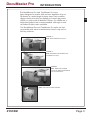
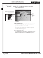
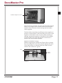
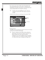
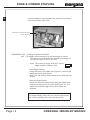
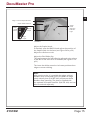
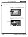
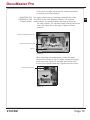
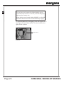
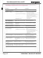
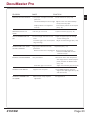
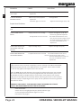
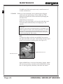
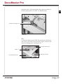
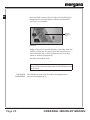
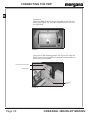
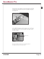
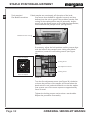
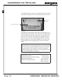
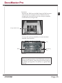
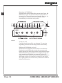
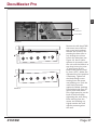
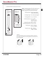
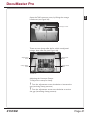
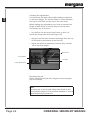
70-169
Issue 2
FEBRUARY 2013
Documaster Pro
(CB/UL)
OPERATORS MANUAL
Part 2 (Booklet Making Unit)
Document Creasing & Automatic
Booklet Making Machine
Morgana Systems Limited
United Kingdom
www.morgana.co.uk
Telephone: ( 01908 ) 608888
Facsimile: ( 01908 ) 692399
CONTENTS
Specifications ....................................1
Introduction .......................................3
Booklet Making ................................10
Edge & Corner Stapling ..................14
Edge Stapling & Folding .................16
The Staple Heads ............................18
Troubleshooting Chart ....................22
Maintenance .....................................26
Appendices
Connecting the TMP ............................. 30
Staple Position Adjustment .................. 32
Sharpening the TMP Blade ..................34
Conveyor Clamp Adjustment .............. 40
Index ..................................................44
CREASING / BOOKLET MAKING
DocuMaster Pro
SPECIFICATION
Intended Use This product is intended to
be used for the stapling,
folding and trimming of
materials as specified.
Electrical
Voltage
115V, 60 Hz or
230V, 50 Hz
Single Phase
(earthed supply required)
Power 150VA exc. TRIM
(115V) 500VA inc. TRIM
20VA Stand-by
Power 200VA exc. TRIM
(230V) 700VA inc. TRIM
30VA Stand-by
Current 4.4A (115V) or
3.0A (230V)
SYSTEM
Page 1
Dimensions
BookMaster Pro 546, 495, 595mm, 70kg
(W,D,H) 21.5, 19.5, 23.4", 154.3lb
BookMaster Pro with 546, 830*, 840mm**, 79kg
Motorised Infeed (W,D,H) 21.5, 32.7, 33.1", 174.2lb
TrimMaster Pro 546, 650, 595mm, 85kg
(W,D,H) 21.5, 25.6, 23.4", 187.4lb
†
Outfeed Conveyor 404, 1050, 720mm , 17kg
(W,D,H) 15.9, 41.3, 28.4", 37.5lb
*Depth without paper tray is 710mm (28.0").
**Height with infeed tray in normal operating position.
915mm (36") with TMP.
†
Noise 74dB
(A)
Production may vary according to operating conditions.
In line with a policy of continual product improvement, the
manufacturer reserves the right to alter the materials or
specification of this product at any time without notice.
Radio Frequency This equipment has been tested and found to comply with
Emissions the limits for a Class A digital device, pursuant to part 15
of the FCC Rules. These limits are designed to provide
reasonable protection against harmful interference when
the equipment is operated in a commercial environment.
This equipment generates, uses and can radiate radio
frequency energy and, if not installed and used in accordance with the instruction manual, may cause harmful
interference to radio communications. Operation of this
equipment in a residential area is likely to cause harmful
interference in which case the user will be required to
correct the interference at his own expense.
WARNING!
The TrimMaster Pro unit contains a motorised guillotine.
It is therefore essential that due care is taken and the
operating instructions adhered to when using the unit.
Also pay particular attention to any specific warnings
given.
Page 2
CREASING / BOOKLET MAKING
DocuMaster Pro
INTRODUCTION
2
The BookMaster Pro and TrimMaster Pro have
been designed to staple, fold and trim booklets of up to
20 sheets, in a wide range of paper sizes. Their modular
design means that they are equally at home being used
offline, or online with a Watkiss Collator. For offline use, a
Motorised Infeed unit is recommended, although a manual Infeed Guide is also available.
The BookMaster Pro and TrimMaster Pro units are also
compatible with other manufacturers' bench-top and table-top collators.
FIGURE 1
BMP with Outfeed Conveyor
FIGURE 2
BMP with Motorised Infeed and
Outfeed Conveyor
FIGURE 3
BMP, TMP and Outfeed
Conveyor (Motorised Infeed
can be fitted also)
FIGURE 4
BMP with manual Infeed Guide
SYSTEM
Page 3
2
The instructions that follow include the set-up and
operating procedure for the BookMaster Pro, the TrimMaster Pro and the Motorised Infeed units. Please ignore
those parts of the instructions that do not apply to your
configuration.
In these instructions the BookMaster Pro is referred to as
the BMP and the TrimMaster Pro is referred to as the TMP.
INSTALLATION
It is recommended that your BookMaster Pro and TrimMaster Pro are sited on a level floor.
Important
This machine must only be plugged into an electrical
supply line of the correct voltage and with a proven
earth. Any damage caused by failure to do so will not
be covered by the warranty. The required machine
voltage is shown on the label on the rear of the unit
(see Figure 5).
SAFETY FIRST
Your BookMaster Pro and TrimMaster Pro units have been
designed with safety as a key feature and incorporate
safety covers which, when opened, will automatically cut
the power to moving parts. However, as with all electrical
equipment, when changing fuses or carrying out operations other than those detailed in this book:
Always first disconnect the machine from the
mains electricity supply.
Page 4
CREASING / BOOKLET MAKING
DocuMaster Pro
Plug in the BMP unit to a single phase power supply of
the correct voltage as indicated by the mains input (see
Figure 5).
2
SWITCHING ON
Mains ON/OFF Switch
Voltage Indicator Label
Mains Input
FIGURE 5
Also ensure the outfeed conveyor cable is connected to
the socket on the BMP (see Figure 6). If the TMP is
installed, ensure that this too is connected (see p. 30).
Status Indicator Light
(Yellow)
Staple Head Indicator Light
(Red)
Conveyor
Socket
FIGURE 6
MOTORISED INFEED
SYSTEM
An optional Motorised Infeed (P/N 041-571) is
recommended. This fits on to the BMP infeed and makes
offline use easier. A paper tray (see Figure 7) is supplied
with the Motorised Infeed.
Page 5
2
An alternative is the BookMaster Infeed Guide,
P/N 041-572 (see Figure 4)
Sidelay
Paper Tray
Motorised Infeed
P/N 041-571
FIGURE 7
Fitting the Motorised Infeed
Loosen the two hand screws (see Figure 8) on either side
of the Motorised Infeed.
Fixing Clip
Hand Screw
FIGURE 8
Page 6
CREASING / BOOKLET MAKING
DocuMaster Pro
2
Connect the Motorised Infeed interface cable to the
socket on the top of the BMP (see Figure 9).
Motorised Infeed Socket
FIGURE 9
Position the Motorised Infeed on the BMP, so that the
fixing clips (see Figure 8) locate inside the BMP infeed.
Fit the rear hand screw (see Figure 10) and then tighten
the two side hand screws.
Length
Adjustment
Hand Screw
Rear Hand Screw
FIGURE 10
Fit the paper tray (see Figure 7) if required.
SYSTEM
Page 7
2
The BMP will automatically start when a set of sheets is
fed into the Motorised Infeed. The BMP will automatically
stop approximately 10 seconds after the last feed, and
return to the standby mode.
The Motorised Infeed will only feed the next set when the
BMP is ready.
Status Indicator Light
The yellow indicator light on the BMP (see Figure 6) shows
the status of the unit.
Indicator Light Mode
Blinking once per second
BMP Status
The unit is ready to run
Constantly illuminated
The unit is running
Blinking rapidly
There is a jam or other error
Not illuminated
BMP/TMP lid is open,
paper is stuck in the paper
path or the unit is not
switched on
Staple Head Indicator Lights
The red indicator lights on the BMP lid (see Figure 6) show
the status of the corresponding staple head.
Page 8
Indicator Light Mode
Staple Head Status
Blinking once per second
The staple cartridge is
about to or has run out
Constantly illuminated
The staple head is selected
and ready to run
Blinking rapidly
There is a staple head jam
or other error
Not illuminated
The staple head is not
selected
CREASING / BOOKLET MAKING
3
DocuMaster Pro
THIS PAGE IS
INTENTIONALLY
BLANK
SYSTEM
Page 9
BOOKLET MAKING
Select Centre Stapling
Using the lever on the BMP (see Figure 16), select centre
staple operation (lift up).
3
SETTING UP THE
BMP & TMP
Edge or Centre Staple Selection
Staple Head Selection
Staple
Head
Select
Staple
Head
Selection
Indicator
Light
Centre
Staple
Edge
Staple
FIGURE 16
Select the Staple Heads
Select the two centre staple heads using the button next
to the lever (see Figure 16). The staple head indicator
lights show which heads are selected.
The position of the staple heads can also be adjusted.
For more details, see page 19.
Adjust the Fold Roller Gap*
The gap between the fold rollers is adjusted using a lever
to the left of the front face of the BMP (see Figure 17).
Page 10
CREASING / BOOKLET MAKING
3
DocuMaster Pro
Fold Roller Adjustment Lever
FIGURE 17
The lever has 11 positions. To move the fold rollers further
apart (i.e. for larger sets or thicker stock) move the lever
upwards. Move the lever down to bring the fold rollers
closer together.
The fold rollers should be set sufficently close together to
produce a neat booklet. If the fold rollers are set too close
together, the booklet covers may be pulled (resulting in
damage around the staples) or the spine of the booklets
may be scuffed. Fine-tune the position of the lever to
produce the best booklets possible.
Adjust the Outfeed Conveyor
Slide the large payout wheels (see Figure 18) up or down
their mounting rail so that they are just nipping the spine
of the book when it is released from the rollers. Use the
scale on the outfeed as a guide.
Scale
Payout
Wheels
FIGURE 18
SYSTEM
Page 11
3
The contact point of the wheels should be aligned with
the required dimension on the scale, as shown by the
dotted line in the photo (see Figure 18). If required, make
any fine adjustments once the job is running.
Tip:
Common sizes are highlighted on the scale. For
example for an A5 (5½ x 8½") book, use the A5
marker.
Hook the trim offcut box (see Figure 19) onto the TMP.
Payout
Wheels
Offcut Box
FIGURE 19
Starting the Job
The BMP will automatically start when the first set of sheets
is placed into the Motorised Infeed.
Tip:
Page 12
There is a sensor on the TMP to detect when the
offcut box is full. Once this sensor is activated, the
BMP will beep after every second booklet
produced. If you stop feeding sets into the infeed,
the BMP will return to standby and beep continously, until the offcut box is emptied (see Figure 19).
CREASING / BOOKLET MAKING
DocuMaster Pro
THIS PAGE IS
INTENTIONALLY
BLANK
SYSTEM
Page 13
4
EDGE & CORNER STAPLING
Corner stapling is only possible if an optional third staple
head is fitted (see Figure 20).
Optional Third Staple Head for
Corner Stapling
FIGURE 20
ORGANISING THE Loading the Motorised Infeed
JOB The staples will be inserted into the feed edge of the set.
The sheets should therefore be loaded accordingly, i.e
feed the set spine-first into the unit.
Note: The maximum sheet width that can be
edge stapled is 250mm, 9.84".
Select Edge Stapling
Using the lever on the BMP (see Figure 21), select edge
staple operation (push down).
Note: This will automatically switch off the fold and trim
actions.
Select the Staple Heads
Select the required staple heads using the staple head
selection button next to the lever (see Figure 21). The
staple head indicator lights show which heads are
selected.
Note:
For edge stapling, select the two centre staple heads.
For corner stapling, select the third head only.
Page 14
CREASING / BOOKLET MAKING
4
DocuMaster Pro
Edge or Centre Staple Selection
Staple Head Selection
Staple
Head
Select
Staple
Head
Selection
Indicator
Light
Centre
Staple
Edge
Staple
FIGURE 21
Adjust the Staple Heads
If required, open the BMP lid and adjust the position of
the staple heads via the lever (see Figure 24 on p.26).
Adjust the clinchers to suit.
Adjust the Fold Roller Gap
The gap between the fold rollers is adjusted using a lever
to the left of the front face of the BMP (see Figure 17 on
p.11).
The Lever should be moved to its lowest position when
edge or corner stitching.
Note:
With certain stocks, it is possible that edge-stitched
booklets may occasionally jam in the BMP. An edge
stitch assistor plate (P/N 907-442) will prevent these
Booklets from jamming. The plate is supplied with
the optional 3rd stapler head kit (P/N 914-414) and can
Also be ordered separately.
SYSTEM
Page 15
EDGE STAPLING & FOLDING
5
If required, it is also possible to edge staple the set and
then fold it. The only limitation to this is that the distance
from the stapled edge to the fold must be at least half the
width of the paper.
Adjustments
Note: The gap between the fold rollers must be set to suit
the set size when edge stapling and folding (see
p. 10).
Note: The maximum sheet width that can be
stapled in this mode is 250mm, 9.84".
Page 16
CREASING / BOOKLET MAKING
DocuMaster Pro
THIS PAGE IS
INTENTIONALLY
BLANK
SYSTEM
Page 17
THE STAPLE HEADS
6
CHANGING THE
When a staple cartridge runs out, the corresponding red
STAPLE CARTRIDGES indicator light (see Figure 22) will blink once per second.
New cartridges are available (P/N 810-022).
To change a cartridge, first open the BMP lid by turning
the handle to the left and lifting (see Figure 22). The lid is
supported by a strut on the right side.
Indicator Light
FIGURE 22
Grasp the cartridge at the top and pull directly away from
the staple head, as shown by the arrow in the photo (see
Figure 23).
Staple Cartridge
Staple Head
FIGURE 23
Page 18
CREASING / BOOKLET MAKING
DocuMaster Pro
ADJUSTING THE The staple heads have two positions. Normally the heads
POSITION OF THE should be in the outer position (138mm, 5.4" between
STAPLE HEADS staple centres). For small booklets the inner position can
be used (115mm, 4.5" between staple centres). Move the
lever (see Figure 24) to the right to select the inner
position.
6
Fit the new cartridge and check the machine operation
by making a few test booklets.
Staple Head Adjustment Lever
Optional third staple head
Clincher
FIGURE 24
When adjusting the staple heads, ensure the staple
clinchers are moved to suit. To adjust, loosen the orange
hand screw (see Figure 25) and slide the clincher fully
across in the required direction. Tighten the hand screw.
Orange Hand Screw
FIGURE 25
SYSTEM
Page 19
6
Note:
You may have to increase the infeed sidelay gap to
access the hand screws. To do this, increase the paper
width on the Creaser unit.
Before placing your hands inside the BMP, you should
disconnect the unit from the mains electricity supply.
``
To close the BMP lid, lift it slightly, push the support strut
(see Figure 26) and close the lid. Turn the handle to the
right to lock in place.
Support Strut
FIGURE 26
Page 20
CREASING / BOOKLET MAKING
6
DocuMaster Pro
THIS PAGE IS
INTENTIONALLY
BLANK
SYSTEM
Page 21
TROUBLESHOOTING CHART
7
The following is a guideline to help solve any problems or errors, if they persist please
call the Morgana Service Department or your Morgana Dealer.
PROBLEM
CAUSE
SOLUTION
Operational Problems
BMP WILL NOT START
The BMP is not plugged in
Fuse has blown on the main input
BMP/TMP lid is open
Plug into mains connection of the
correct type and voltage.
On 220-240V machines there are
two 5 amp fuses in the mains input
connector, check and replace as
necessary. On 115V machines they
are 10 amp fuses.
Close the lid
BMP STATUS INDICATOR
LIGHT IS BLINKING RAPIDLY
There is a jam or other error in the
unit
Clear the jam (see p. 24)
BMP STATUS INDICATOR
LIGHT IS NOT ILLUMINATED
BMP/TMP lid is open or unit is not
switched on
Close the lid/switch on the unit
BMP BEEPS CONTINUOUSLY
Offcut Box is full
ONE OR BOTH STAPLE HEADS
ARE NOT ACTIVATED
Staple heads are not selected
FOLD IS NOT ACTIVATED
BOOK IS NOT TRIMMED
EDGE STAPLE FUNCTION
NOT WORKING
Empty Offcut Box (see p. 12)
Select required staple heads (see p.
10)
A staple head error has occurred
The heads should self clear. If not,
turn the unit off and on again to free
the head. If this does not work
contact your local Service
Department
Unit is in edge staple mode
Trim not selected.
Trim position is set off the edge of
the sheet.
Edge staple not selected
EDGE STAPLED BOOKLETS Leading edge of booklet is catching
ARE JAMMING IN THE BMP
the edge stitch deflector shaft
Page 22
Move lever into centre staple
position (see FIGURE 21 on p.15)
Select ‘Trim On’ on creaser unit
Reset trim position on creaser unit
Move lever to correct position and
select staple head (see p. 10)
Fit edge stitch assistor plate (see p.
15)
CREASING / BOOKLET MAKING
DocuMaster Pro
CAUSE
SOLUTION
STAPLE IS NOT ON THE FOLD
Loose paper or staples in the fold
Locate and remove (see p. 24)
plate area.
The infeed sidelays are set too tight Adjust so that the infeed sidelays
barely touch the paper
Staple position is not adjusted
Fine tune the position of the staples
correctly
(see p. 32)
FINISHED BOOKLET IS TOO
Fold roller gap is too wide
7
PROBLEM
Adjust the fold roller gap (see p. 10)
LOOSE
TOP JOG DAMAGE ON THE
SET
The sheet length has been set too
Adjust the paper input size setting
short
on the creasing unit
Fold roller gap is too narrow (when Adjust the fold roller gap (see p. 10)
edge stitching)
BOOKLETS WILL NOT STACK
ON THE CONVEYOR
Large payout wheels incorrectly
Reposition (see p. 11)
positioned
Electrical connection is unplugged Plug in electrical connection
between the BMP/TMP and the
outfeed conveyor
BOOKLET COVER IS MARKED
Dirty fold rollers
Fold roller gap is too narrow
Clean them with a cloth dampened
with soapy water or alcohol (isopropanol). Do NOT use blanket wash
(see p. 33)
Adjust the fold roller gap (see p. 10)
CANNOT CLOSE BMP LID
Support strut is in place
Lift the BMP lid slightly, push the
support strut (see Figure 34 on p.31)
and close the lid
BOOKLET IS TRIMMED OUT
OF SQUARE
TMP conveyor clamp requires
adjustment
See Appendix 4
SYSTEM
Page 23
PROBLEM
SOLUTION
TMP conveyor clamp requires
adjustment
See Appendix 4
7
BOOKLETS ARE TRIMMED
TOO SHORT
CAUSE
COVER IS DAMAGED
AROUND STAPLES
TMP conveyor clamp requires
adjustment
Fold roller gap is too narrow
See Appendix 4
Adjust the fold roller gap (see p. 10)
Staple Head Problems
ONE OR BOTH LEGS TURN
OUT
Incorrect clincher alignment
STAPLE COMES OUT IN
PIECES
Staple jammed in the cartridge
A staple head error has occurred
Re-align (see p. 19)
Inspect cartridge (see p. 18) and
remove any jammed staple wire.
The heads should self clear. If not,
turn the unit off and on again to free
the head. If this does not work contact your local Watkiss service
department.
STAPLE HEAD INDICATOR
LIGHT BLINKS ONCE PER
SECOND
Staple cartridge empty
Replace cartridge (see p. 18)
STAPLE HEAD INDICATOR
LIGHT BLINKS RAPIDLY
A staple head error has occurred
The heads should self clear. If not,
turn the unit off and on again to free
the head. If this does not work contact your local Watkiss service
department
Paper Jams
Paper Jams are most commonly caused by: incorrect settings of the Motorised Infeed
sidelays; by paper jammed in the TMP infeed or the conveyor. Other causes include
the use of curly paper and staples stuck in the clinchers.
Open the BMP lid (this will disconnect the power for safety) and remove any jammed
sets. Check carefully and correct any faulty adjustments that caused the jam to occur
(as detailed). If there are staples stuck in the clinchers, remove with a pair of pliers.
Paper jams in the TMP can be caused by offcuts obscuring the sensor in the conveyor.
The metal conveyor lid (see Figure 29 on p.27) can be opened to remove any jammed
sets and trim offcuts.
WARNING: DISCONNECT THE MACHINE FROM THE MAINS ELECTRICITY
SUPPLY BEFORE WORKING NEAR THE BLADE AREA
Error Indication
Certain errors are highlighted by the yellow indicator light
or the red staple head indicator lights. For more
information see page 8.
Page 24
CREASING / BOOKLET MAKING
DocuMaster Pro
THIS PAGE IS
INTENTIONALLY
BLANK
SYSTEM
Page 25
MAINTENANCE
7
The BMP and TMP units require only a small amount of
routine maintenance.
CLEANING
Build up of set-off powder, ink or general dust will gradually impair the performance of your BMP and TMP.
Optimum performance will be obtained by keeping the
machine clean.
Fold Roller and Conveyors
Build-up of set-off powder or ink on the fold rollers and
conveyor belts will eventually cause slippage or ink
transfer.
Warning!
Access to the manual cranking points on the BMP and
TMP requires the side covers to be removed. For safety
reasons this procedure should therefore only be conducted by authorised personnel. Disconnect the power
before removing the side covers.
BMP
To clean the rollers and belts on the BMP, first remove
the right hand side cover (two x M5 button screws) to give
access to the manual cranking point (see Figure 27).
Right Hand Side Cover
M5 Button Screw
FIGURE 27
Open the BMP lid to access the fold rollers. Using a 10mm
A/F spanner (wrench), manually crank the BMP by turning
the nut (see Figure 28) clockwise, and clean the rollers.
Page 26
CREASING / BOOKLET MAKING
and belts with a cloth dampened with soap and water or
alcohol (isopropanol). Do NOT use blanket wash.
8
DocuMaster Pro
Manual Cranking Point
FIGURE 28
TMP
To clean the belts on the TMP, first remove the left hand
side cover (two x M5 button screws) to give access to the
manual cranking point (see Figure 29).
Orange Hand Screw
TMS Lid
M5 Button Screw
Left Hand Side Cover
FIGURE 29
SYSTEM
Page 27
8
Open the TMP conveyor lid (see Figure 29) by lifting the
orange hand screw (this doesn’t need to be loosened,
just use it as a handle).
Manual
Cranking
Point
FIGURE 30
Using a 19mm A/F spanner (wrench), manually crank the
TMP by turning the nut (see Figure 30) clockwise, and
clean the belts with a cloth dampened with soap and
water or alcohol (isopropanol).
Do NOT use blanket wash.
Warning!
Ensure that hands are kept clear of the TMP blade area
at all times.
TMP BLADE
SHARPENING
Page 28
The TMP blade (and anvil) should be sharpened when
required (see Appendix 3).
CREASING / BOOKLET MAKING
8
DocuMaster Pro
THIS PAGE IS
INTENTIONALLY
BLANK
SYSTEM
Page 29
A1
CONNECTING THE TMP
Procedure
Open the BMP lid by turning the handle to the left and
lifting (see Figure 31). The lid is supported by a strut on
the right side.
FIGURE 31
Line up the TMP docking plates (see Figure 32) with the
BMP. Connect the power and communications cables to
the sockets on the BMP.
Communications Cable
Power Cable
Docking
Plate
FIGURE 32
Page 30
CREASING / BOOKLET MAKING
Push the two units together so that the hooks on the TMP
docking plates align with the holes in the BMP side plates
(see Figure 33).
A1
DocuMaster Pro
FIGURE 33
Lift the BMP lid slightly, push the support strut (see Figure
34) and close the lid. Turn the handle to the right to lock
the TMP in place.
Support Strut
FIGURE 34
Hook the Outfeed Conveyor onto the support posts on
the TMP and connect the interface cable.
SYSTEM
Page 31
A2
STAPLE POSITION ADJUSTMENT
Tools required
Flat Blade Screwdriver
If both staples are consistently off the spine of the book
first ensure that the BMP is adjusted correctly and that
delivery into the unit is good. If the problem persists, fine
tuning of the staple position may be necessary. Adjustment is via the central screw on the fold plate mechanism,
located behind the perspex cover (see Figure 35).
Fold Position Fine Tuning
FIGURE 35
If necessary, adjust the fold position until the screws align
with the holes in the perspex cover. Using a flat blade
crewdriver, loosen the two locking screws (see Figure
36).
Turn Clockwise to
Lower the Staples
Locking Screw
Fine Adjustment Screw
Locking Screw
Turn Anticlockwise to
Raise the Staples
FIGURE 36
Turn the fine adjustment screw (see Figure 36) clockwise
to lower the position of the staples (as viewed when the
book exits the unit) and anticlockwise to raise the staples.
One quarter turn of the screw equates to approximately
2mm of travel.
Tighten the locking screws and produce a test booklet.
Repeat the procedure if necessary.
Page 32
CREASING / BOOKLET MAKING
DocuMaster Pro
THIS PAGE IS
INTENTIONALLY
BLANK
SYSTEM
Page 33
A3
SHARPENING THE TMP BLADE
The TMP blade and anvil are located behind the conveyor
assembly (see Figure 37) at the docking end of the unit.
Conveyor
Cover
Conveyor Assembly
FIGURE 37
Periodically all TMP blades will require re-grinding. Poor
grinding will result in poor life, and can cause cracks and
nicks in the blade. We therefore offer the guidelines on
page 39 which should accompany the blade and anvil
when they are sent for regrinding. Whenever the TMP
blade is reground, check the condition of the anvil also.
This will only require regrinding if it has become damaged.
Warning!
This procedure is potentially hazardous and should only
be conducted by suitably skilled personnel. Disconnect
the power before removing the conveyor assembly.
Handle the blade with extreme caution and keep hands
clear of cutting edges at all times.
Parts Required (if necessary)
Tools Required
TMP/1189 onwards:
3mm allen key
253-835 TrimMaster blade & guide
4mm allen key
TMP/1188 and earlier:
6mm allen key
253-173 TrimMaster blade
10mm allen key
19mm spanner
Page 34
CREASING / BOOKLET MAKING
Procedure
Separate the TMP from the BMP. Open the TMP conveyor
cover (loosen the orange hand nut). Remove the two
orange hand screws that secure the conveyor assembly
to the TMP unit (see Figure 38).
A3
DocuMaster Pro
Orange Hand Screws
FIGURE 38
Lift away the conveyor assembly to reveal the blade
assembly (see Figure 39).
Anvil
Blade
Mark Along
Here
FIGURE 39
Important
Note the angled position of the TMP blade and with a
marker pen or similar, mark along the bottom edge of
the blade (see Figure 39). This will act as a guide when
refitting.
SYSTEM
Page 35
A3
Removing the TMP Blade
Slightly loosen all five blade fixing screws (see Figure 40).
Remove the outer two screws and screw them into the
locator holes. These will now act as handles. Remove the
remaining screws and carefully lift the blade away.
Immediately put the blade away safely.
FIGURE 40
Check the anvil
Carefully check the anvil for any damage. If it requires
regrinding, remove the five fixing screws and lift away.
Refitting the TMP blade and anvil
Slacken the anvil adjuster screws back two revolutions.
Position the anvil fully back towards the conveyor and
lightly tighten the anvil fixing screws. Affix the blade using
the five blade fixing screws but do not tighten. Using the
mark made when the blade was removed, adjust the
angle of the blade. Ensure that it does not protrude above
the clamp at point 'A' or below it at point 'B' (see Figure
42). Lightly tighten the centre screw, sufficient to hold the
blade in this position.
Page 36
CREASING / BOOKLET MAKING
A3
DocuMaster Pro
Manual
Crank Drive
Access Hole
FIGURE 41
FIGURE 42
SYSTEM
Remove the left hand TMP
side cover (two x M5 button screws and washers).
Release the clutch by depressing the lever (see arow) through the access
hole in the side plate (see
Figure 41). Use a 19mm
spanner to manually crank
the unit until the blade is at
top dead centre. At point
'C' (see Figure 42) the
blade must pass the anvil
by 1mm (1/25"). Make fine
adjustments to the position
if necessary. Tighten all
the blade fixing screws
starting from the centre
and working out. Push the
anvil firmly forwards
against the blade (pushing
from behind with your fingers at each end). Maintain a light pressure on the
back of the anvil whilst
tightening the anvil fixing
bolts starting from the
centre and working out.
Lightly tension the anvil
adjuster screws against
the anvil.
Page 37
A3
Final adjustment
Release the clutch and manually crank slowly several
rotations to check that the blade passes the anvil smoothly
without obstruction.
Place a single sheet of paper (large sheet size) between
the blade and the anvil and manually crank to produce a
test cut.
Warning!
Ensure that hands are kept clear at all times.
Check that a clean cut is obtained across the full width
of the blade. If necessary loosen the anvil fixing screws
at the point where adjustment is needed, apply additional
pressure to the anvil adjusting screws (1/6th turn at a time)
and re-tighten the anvil fixing screws.
Perform another test cut and make further adjustments if
necessary.
Hook the conveyor assembly onto the support posts and
push into position. Secure with two M5 button screws and
washers (see Figure 38).
Fit the side cover and secure.
Page 38
CREASING / BOOKLET MAKING
DocuMaster Pro
BLADE
Note:
2 faces must
be flat to within
0.03mm
ANVIL
Note.
2 faces must
be flat to within
0.01mm
Note: TrimMaster blade 253-835 is fitted with a
guide leg. This must be removed when the
blade is reground and refitted afterwards.
A3
TrimMaster Blade Grinding Instructions
Blade Material High Carbon High
Chrome (Aisi D2/D3)
Grinding Angle See drawing alongside
Grinding Wheel Cup or Cylinder
Grinding Material Grit : 46-60
Hardness : G-H
Bond : Vitrified
Peripheral speed 20-26 (V M/S)
of the grinding wheel 65-85 (V Ft/S)
This edge must
be straight to
within 0.04mm
Table Speed 20-26 (V M/Min)
65-85 (V Ft/Min)
Feed per pass 0.01 - 0.02mm
0.0004 - 0.0008"
Important:
Grind In This
Direction Only
Honing
After re-grinding, the burr should be carefully removed
by honing. The quality of honing affects the useful life of
the cutting edge.
Correct
SYSTEM
Incorrect
Page 39
CONVEYOR CLAMP ADJUSTMENT
A4
The TMP conveyor clamps are set to a default position at
the factory, which gives a good trim over a wide variety
of booklet thicknesses.
However, when trimming unusually thick or thin booklets,
the conveyor clamps may need to be adjusted.
If the conveyor clamps are set too loose, the booklet may
not be delivered correctly to the trim stop, or it may
bounce
against the trim stop. This will result in the following
problems:
!
!
booklets are trimmed out of square (this may also
indicate that the left and right conveyor clamps are set
unevenly).
Booklets are trimmed too short.
If the conveyor clamps are set too tight, the following
problem may occur:
!
Tools required
4mm allen key
2 off 150mm/6" rule
Page 40
The cover of the booklets are pulled, resulting in dam-
Procedure
On the BMP control panel, set the paper size to A4>A5
(regardless of the booklet size). Once the BMP beeps to
confirm it is ready, disconnect it from the mains.
CREASING / BOOKLET MAKING
Open the TMP conveyor cover, by lifting the orange
handscrew (see Figure 43).
A4
DocuMaster Pro
Conveyor cover
FIGURE 43
There are two clamp roller shafts, which are adjusted
using a 4mm allen key (see Figure 44).
Adjustment
screw
Adjustment
screw
Clamp Roller
Shaft
Clamp Roller
Shaft
FIGURE 44
Adjusting the Conveyor Clamps
To adjust the conveyor clamp:
!
Turn the adjustment screws clockwise to increase the
gap (reducing clamp pressure)
!
Turn the adjustment screws ant-clockwise to reduce
the gap (increasing clamp pressure)
SYSTEM
Page 41
A4
Checking the adjustments
It is important that both clamp roller shafts are adjusted
to the same height. The factory default is 17mm between
the top of each shaft and the top of the wire frame.
When making any adjustments, you must re-measure the
height of both shafts, to ensure they are set the same.
The easiest way to do this is:
• Lay the first rule across the wire frame, so that it is
above the clamp roller shaft (see Figure 45)
• Using the second rule, measure the height from the top
of the shaft to the bottom of the first rule
• Adjust the shafts as necessary to ensure they are both
set to the same height
Wire Frame
Second Rule
First Rule
Clamp Roller Shaft
FIGURE 45
Restarting the job
Before restarting the job, don’t forget to reset the paper
size as necessary.
Note:
It is important to return both clamp roller shafts to the
factory default height of 17mm before booklets of a more
typical thickness are produced.
Page 42
CREASING / BOOKLET MAKING
A4
DocuMaster Pro
THIS PAGE IS
INTENTIONALLY
BLANK
SYSTEM
Page 43
INDEX
A
adjustable fold rollers 10
adjustment of conveyor clamp 40–42
B
blade sharpening, tmp 28
booklet making 10–12
setting up the bmp 10-12
C
centre staple selection 10
clamp roller shafts 41, 42
connecting the tmp 30–31
conveyor clamp adjustment 40–42
corner & edge stapling 14–15
D
dimensions 2
docking plates, tmp 30
E
edge & corner stapling 14–15
edge stapling & folding 16
errors - see troubleshooting
F
Fold rollers, adjustable 10
I
infeed - see motorised infeed
installation 4
introduction 3–8
J
jams 24
M
maintenance 26–28
cleaning the units 26
manual cranking point, bmp 26
manual cranking point, tmp 27
motorised infeed
fitting the motorised infeed 6
using the motorised infeed 14
P
paper jams 24
payout wheels adjustment 11
power supply 1
R
radio frequency emissions 2
S
safety 4
setting up the bmp 10–12
centre staple selection 10
outfeed conveyor adjustment 11
trim offcut box 12
side stapling 14–15
specifications 1
staple cartridges, changing 18
staple head indicator lights 8
staple heads 18–20
adjusting 19
clinchers 19
selecting 14
staple cartridges, changing 18
staple position fine tuning 32
status indicator light 8
switching on 4
T
tmp blade sharpening 34–39
final adjustment 38
honing 39
refitting the blade and anvil 36
removing the blade 36
trim offcut box 12
troubleshooting 22–24
operational problems 22
paper jams 24
staple head problems 24
O
offcut box 12
outfeed conveyor adjustment 11
Page 44
CREASING / BOOKLET MAKING
DocuMaster Pro
SYSTEM
Page 45