1
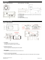
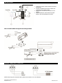
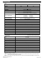
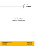
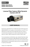
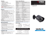
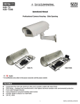
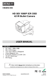
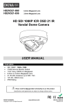
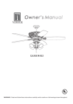
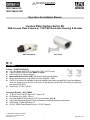
Please read the Operational Manual before attempting to use this product. SIR-754AILP-IO SIR-754AILP-IOP Operation & Installation Manual License Plate Capture Series Kit D&N License Plate Camera w/ 11 IR LED Illuminator Housing & Bracket SHM-7540LPDN-IO HI11-TKHBL FEATURES Camera – SHM-7540LPDN-IO 1/3” Sony Super HAD CCD II; Sony HQ-1 DSP; 540 TV Lines 5.0mm~60.0mm Auto Iris Lens, Made in Japan 0.08 Lux @ F1.0; I/O Input/Output Mechanical IR Cut Filter (ICR); Advanced 8-step Manual Shutter Built-in Auto Sense-up; High Gain/Low Noise Amplifier - DNR CAR-DC Iris Control is available to achieve reliable license plate recognition for road surveillance when car speed is up to 90 mi/hr (150 km/hr) in the daytime and 90 mi/hr (150 km/hr) at night time with external IR LEDs. Dual Power 12V DC / 24V AC Housing & Bracket – HI11-TKHBL 11 Super Power IR LED, 6pcs x 25° / 5pcs x 45° IR Distance up to 395ft / 120m User Adjustable IR LED Intensity (VR), Factory Default 80% Fully-Cable Managed Bracket; Uses professional rust-proof stainless steel screws IP66 Rating; Heater & Blower; I/O 24V AC, 60VA (Power Ready Plug for 12V DC Camera) Please see page 6 for details Copyright 2010. All Rights Reserved. www.okinausa.com 1 REV012011-V03 DIMENSIONS Camera – SHM-7540LPDN-IO Housing & Bracket – HI11-TKHBL Max Load: 3500g Material: Die-cast aluminum alloy with light ivory powder coated and stove finish Scan Angle: 180° Title Angle: 90° Net Weight: 900g Fixing: 3 Screws with bushings PARTS & FUNCTIONS Camera – SHM-7540LPDN-IO Note: Do Not Remove Screws Lens Mount This mount is used to install a CS mount lens. CS adaptor ring is required if using a C mount lens. CS Mount Fixing Screw Screw for fixing mount and adjusting back focus if needed. Mount Adaptor This adaptor can be attached to either the top or bottom of unit. Auto Iris Lens Connector (4-pin type) The lens connector supplies the auto-iris lens (not supplied) with DC power and a video signal or DC control signal. Copyright 2010. All Rights Reserved. www.okinausa.com 2 REV012011-V03 2 7 4 5 0 1 3 6 ME/AES Shutter Control (0) 1/100 (120) sec. (1) (2) 1/350 sec. (3) 1/610 sec. (4) 1/1120 sec. (5) 1/2000 (6) 1/3240 sec. (7) 1/4000 1/190 sec. sec. sec. Camera to object moving speed Shutter Speed 45~60ft (15~20m) 60~100ft (20~35m) 100~180ft (35~60m) 1/100 sec 1/190 sec 1/350 sec 15~35 mi/hr 45~45 mi/hr (30~60 Km/hr) (45~75 Km/hr) 20~40 mi/hr 35~53 mi/hr 1/1120 sec (35~65 Km/hr) (55~85 Km/hr) 25~45 mi/hr 40~60 mi/hr 1/2000 sec (45~75 Km/hr) (65~95 Km/hr) 30~50 mi/hr 50~62 mi/hr 50~62 mi/hr 1/3240 sec (50~80 Km/hr) (80~100 Km/hr) (80~100 Km/hr) 35~55 mi/hr 55~65 mi/hr 55~65 mi/hr 1/4000 sec (60~90 Km/hr) (90~105 Km/hr) (90~105 Km/hr) *The table above is only for reference. Values may change due to the angle of the camera and the installation location. 1/610 sec Control Switch SW1. BLC: Backlight Compensation OFF/BLC switch SW2. Day/Night Mode: D/N / Color switch SW3. AGC: Automatic Gain Control AGC/S.AGC switch SW4. Sync Mode: Sync Mode Selection L.L/INT switch Video Connector Output for connecting to a video monitor or recorder. Auto Iris Mode Selection Switch For switching the output from the auto iris connector. Shutter speed is fixed at 1/100(120) sec. when switch is set to DC or VIDEO position. DC: To be set when using a auto iris lens. Be sure to adjust proper DC level for D&N operation. CAR-DC: To be set when using for license plate capture. (Car speed is up to 90 mi/hr (150 km/hr) in the daytime and 90 mi/hr (150 km/hr) at night with external IR LEDs). VIDEO: To be set when using an auto iris lens with built-in amp. V.P. (Vertical Phase) Adjustor Used to adjust the vertical phase of the video output signal Power Input Terminal Connect the power supply of 12V DC or 24V AC. Copyright 2010. All Rights Reserved. www.okinausa.com 3 REV012011-V03 Housing & Bracket – HI11-TKHBL Camera 1. 2. 3. 4. 5. 6. 7. 8. 9. 10. 11. 12. 13. 14. 15. 16. 17. 18. 19. 20. 21. Lens Cap with Heater Temper Glass IR LED: 7pcs or 11pcs Super Power IR LED with Refractor IR Board and IR Board Bracket Universal IR Control Circuit Board: When the IR light turns on, it automatically adjusts the color to monochromatic through the universal IR control circuit. Camera Bracket Power Supply Unit: 24V AC input, 60VA Blower and Blower Bracket Thermostat Switch Video Input BNC Male Connector: Connect to camera Video Out BNC Female Connector: Connect to monitor Terminal Board Fuse Holder: With 250V / 3.15A fuse AC IN Terminal block: 24V AC external power input OUTPUT_1 Terminal block: Plug and fix the power cable of camera OUTPUT_2 Terminal block: To power supply unit VR: Adjust VR to set Infrared LED activation level Factory default 80% -- If there is not enough IR light, adjust the level to maximum 100% Thermostat Switch: Turns on at 35C / 95F and turns off at 25C / 77F for Blower Ground wire: To top cover 12V DC Power-in jack: To camera / center+, outer- Internal / Line Lock (AC Version Only) When using a camera which requires a 24V AC power input, please run a separate power line to the camera Internal / Line Lock (AC Version Only); Must use 24V AC camera with Line Lock (12V DC cameras do not have line lock). Flying Bare Lead Wire: When the wire is not in use, cover it with the screw-on connector or tape the tip with tape to prevent damages caused by the bare lead wire. Copyright 2010. All Rights Reserved. www.okinausa.com 4 REV012011-V03 INSTALLATION 1. Loosen two screws on both sides of the camera bracket first. 2. Use the provided screw to fix the camera (not included) on the camera bracket. 3. Adjust zoom, focus and iris of the lens on the camera. 4. Adjust the direction of the camera for proper position, after finished tighten all screws. How to install cables through the mounting bracket: EXTERNAL POWER INPUT CONNECTION NOTE: When using two-cord power cable, please connect them to “Live” and “Neutral.” Copyright 2010. All Rights Reserved. www.okinausa.com 5 REV012011-V03 SPECIFICATIONS Camera PIC Model TV System Image Sensor Resolution ; DSP Total Pixels Video Output Minimum Illumination IR Sensitivity Mechanical IR Cut Filter (ICR) Electronic Shutter Speed Intelligent Shutter Speed Back Light Compensation Auto Gain Control Auto White Balance Day/Night I/O DNR / Sens-up Scan System Synchronization S/N Ratio Adjustment VR Automatic IRIS ; Connector Lens Mount Power Supply Power Consumption Operation Temperature Storage Humidity Storage Temperature Dimension Weight L-806 SHM-7540LPDN-IO SHM-7540LPDN-IOP NTSC PAL 1/3” Sony Super HAD CCD II 540 TV Lines ; Sony HQ-1 811(H) x 508(V) 795(H) x 596(V) 1.0Vp-p Composite / 75ohms 0.08 Lux @ F1.0 (Color mode automatically switches to B/W mode under 2 Lux) 700~1100nm External controlled by D&N IO Color (In: 0V or normal open) / D&N (In: 5~12V DC or normal close) AES: 1/50(60) sec ~ 1/100,1000 sec (0) 1/100(120) sec (1) 1/190 sec (2) 1/350 sec (3) 1/610 sec (4) 1/1120 sec (5) 1/2000 sec (6) 1/3240 sec (7) 1/4000 sec Capturing license plate for vehicle speeds up to 90 mi/hr (150 km/hr) in the daytime and 90 mi/hr (150 km/hr) at night with external IR LEDs ON/OFF Switchable AGC / Super AGC AWB Mechanical IR Cut Filter (ICR); D/N / COLOR Switchable Yes Automatic; High Gain/Low Noise Amplifier 2:1 Interlace Internal / Line Lock (AC Version Only) More than 50dB (S.AGC OFF) DC Level, L.L. V-phase Video/DC ; D4 IRIS Jack CS/C (with adaptor) 12V DC / 24V AC 3.0W 14F ~ 122F / -10oC ~ 50oC RH 80% or less -4oF ~ 140oF / -20oC ~ 60oC 4.72”(L) x 2.36”(W) x 1.97”(H) / 120mm(L) x 60mm(W) x 50mm(H) 0.88 lbs / 400g Specifications are subject to change without notice Housing & Bracket Model HI11-TKHBL LED Quantity IR LED Beam Angle IR Wave Length IR Distance IR Light On/Off Heater Control Blower Control IP Rating Temper Glass Thickness Mounting Bracket Construction Coating Power / Transformer* Power Consumption Dimension Camera Space Weight 11 Super Power IR LEDs 6pcs 25° / 5pcs x 45° 850nm 395ft / 120m Auto Light Sensor Control 64°F / 18°C (on) ; 82°F / 28°C (off) 95°F / 35°C (on) ; 77°F / 25°C (off) IP66 4mm Full-Cable Management Die-Cast Aluminum Alloy Ivory Powder Stove 24V AC (+/-10%), 60VA 16 Watts 16.73”(L) x 6.30”(W) x 6.50”(H) / 425mm(L) x 160mm(W) x 165mm(H) 7.87”(L) x 4.33”(W) x 4.53”(H) / 200mm(L) x 110mm(W) x 115mm(H) 7.72 lbs / 3500g (w/out bracket) / 11.75 lbs / 5330g (with bracket) Specifications are subject to change without notice *Power Supply / transformer not included NOTE 1: IR light distances are entirely dependent upon environmental site conditions and the location at which the unit is situated. The type of camera being used is also very important. NOTE 2: Factory default for the IR LED activation level is 80%. If there is not enough IR light, adjust the VR level to maximum 100%. Copyright 2010. All Rights Reserved. www.okinausa.com 6 REV012011-V03 PACKAGE CONTENTS One (1) SHM-7540LPDN-IO/SHM-7540LPDN-IOP Camera One (1) HI11-TKHBL IR Illuminator Housing One (1) Fully-Cable Managed Bracket One (1) Main Accessories Pack Three (3) Rust-proof Stainless Steel Wall Screws Three (3) Rust-proof Stainless Steel Mounting Screws Three (3) Stainless Steel Washers Three (3) Plastic Washers One (1) Allen Wrench One (1) Secondary Accessories Pack Three (3) Screw-on Connectors One (1) Rubber Pad One (1) Rust-proof Stainless Steel Camera Screw One (1) Plastic Washer One (1) Operational Manual * For any returns, please include all components listed above with original packaging in Resalable Condition. Absolutely No Returns will be accepted if any component is missing/damaged or if any cable is cut or tampered with. CAUTIONS 1. Never point the camera toward the sun Do not expose the lens directly to the sun or to strong light as this may damage the pick-up device. 2. Handle this camera with care Avoid any shock or bumping of the camera. Improper handling could damage the camera. 3. Requires a proper operating environment This camera is designed for outdoor or indoor use. The allowable temperature range for operation of this camera is between 14F ~ 122F / -10C ~ 50C and the allowable humidity is 80%RH maximum. 4. Clean the front face to the pick-up device It is recommended that the pick-up device surface be cleaned before lens installation or whenever the lens is changed. Cleaning should be done by using a chamois, a very fine soft cloth, lens tissue, or cotton tipped applicator and ethanol to carefully remove any fingerprint or dust. 5. Check the power source voltage The power source voltage should be within the specified range. (Camera must meet the specifications). Camera must be connected to a surge protector at all times. 6. Objects and liquid entry Never push objects of any kind into this camera as this may touch dangerous voltage points of short out parts that could result in a fire or electric shock. Never spill any kind of liquid on the video product. 7. Servicing Do not attempt to service this video product by yourself as opening or removing covers may expose you to dangerous voltage or other hazards. Refer all service to qualified servicing personnel. 8. Damage requiring service Unplug this video product from the wall outlet and refer service to qualified servicing personnel under the following conditions: a. When the power supply cord or plug is damaged. b. If liquid has been spilled, or objects have fallen into the video product. c. If the video product has been dropped or the cabinet has been damaged. d. When the video product exhibits a distinct change in performance. WARRANTY OKINA USA Products are covered under warranty for one year from the date of purchase. The warranty will automatically be voided if any of the following occurs: 1. Product sticker is removed If the product sticker is removed, we will not be able to confirm any information regarding when and where the product was purchased. We have no other way to verify the purchase record without the serial number on the product sticker; therefore, it should not be removed. 2. Product is modified in any way If the product is scratched, damaged, or modified in a manner not described in this manual, the warranty will be voided immediately. It is the customer’s responsibility to keep the product in good condition. 3. Power cable is cut The power cable and any other cable should not be tampered with. Cutting or modifying of the cables will result in termination of the warranty. Copyright 2010. All Rights Reserved. www.okinausa.com 7 REV012011-V03 Copyright 2010. All Rights Reserved. www.okinausa.com 8 REV012011-V03