1
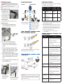
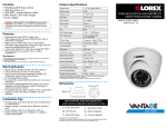
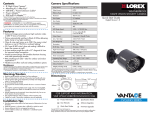
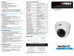
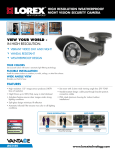
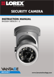
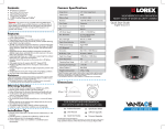
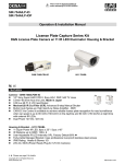
Contents
•High Resolution Color Camera with cable passthrough stand
•Mounting screws x 3 / Allen key x 1
•60ft BNC / power extension cable
•BNC female / RCA male adapter
•Power adapter
WARNING - A REGULATED UL / CSA APPROVED power supply is
REQUIRED for use with this camera. Use of a non-regulated, non-conforming
power supply can damage this product and voids the warranty.
Features
• High resolution 1/3” image sensor produces 540TV lines of
resolution
• Night vision up to 50ft (15m) away in total darkness*
• Anti-glare feature ensures clear images under strong lighting
conditions
• Accurate colors with Lorex’s automatic light-filtering technology
• Split glass design minimizes IR reflection
• See more with 3.6mm wide viewing angle lens (78° FOV**)
• Vandal-resistant design: cable pass-through bracket protects
connection cables
• IP66 rated aluminum housing for indoor / outdoor
installations***
Disclaimers:
* Infrared illumination range under ideal conditions. Actual range and clarity may vary
depending on scene / object reflection and camera application.
** Field of View, diagonal
*** Not intended for submersion in water. Installation in a sheltered location recommended.
Warning/Caution
• Read this guide carefully and keep it for future reference
• Follow all instructions for safe use of the product and handle
with care
• Use the camera within given temperature, humidity and voltage
levels noted in Camera Specifications
• Do not disassemble the camera
• Do not point the camera directly towards the sun or a source of
intense light
• Use only the supplied regulated power supply. Use of a nonregulated, non-conforming power supply can damage this
product and voids the warranty
• Periodic cleaning may be required. Use a damp cloth only. Do
not use harsh cleaners or aerosol cleaners.
• The supplied extension cable is rated for surface mounting only
• Cables for in-wall / floor-to-floor installations are sold separately
Installation Tips
• Point the camera where there is the least amount of obstructions
(i.e. tree branches)
• Install the camera in a location that is difficult for vandals to
reach
• Secure cabling so that it is not exposed or easily cut
• Camera rated for outdoor use. Installation in a sheltered location
recommended
Camera Specifications
Image Sensor
1/3” Color Image Sensor
Video Format
NTSC
Effective Pixels
H: 720 V: 480
Resolution
540 TV Lines
Scan System
2:1 Interlace
Sync System
Internal
S / N Ratio
48dB (AGC Off)
Iris
AES
AES Shutter Speed
1/60 ~ 1/25,000 sec.
Min. Illumination
0.1 Lux without IR LED
0 Lux with IR LED
Video Output
Composite 1.0Vpp @ 75ohm
Lens / Lens Type
3.6mm F2.0 / Fixed
FOV (Diagonal)
78°
Termination
BNC Type
IR LED Qty. / Type
18 pieces / 850nm
Night Vision Range*
50ft / 15m
Power Requirement
12V DC ±10%
Power Consumption
Max. 300mA (w / IR)
Operating Temp. Range
14° ~ 122°F / –10° ~ 50°C
Operating Humidity Range
< 90% RH
Environmental Rating**
IP66
Weight (including stand)
0.8lbs / 0.4kg
HIGH RESOLUTION
IR NIGHT VISION CAMERA
Quick Start Guide
English Version 1.0
* IR Illumination Range under ideal conditions. Objects at or beyond this range may be partially or
completely obscured, depending on the camera application.
** Not intended for submersion in water. Installation in a sheltered location recommended.
Dimensions
67mm / 2.6”
189mm / 7.4”
60mm / 2.4”
FOR SUPPORT AND INFORMATION,
VISIT WWW.LOREXTECHNOLOGY.COM
Product Information
Specification Sheets
User Manuals
Software Upgrades
Quick Start Guides
Firmware Upgrades
Copyright © 2012 Lorex Technologies Inc.
As our products are subject to continuous improvement, Lorex reserves the right to modify product
design, specifications and prices, without notice and without incurring any obligation. E&OE
LBC5450
Installing the Camera
ATTENTION - Test all connections and ensure the camera is working
correctly prior to permanent installation by temporarily connecting the
camera(s) and cable(s) to the viewing / recording solution.
Connecting the Camera
To Camera:
Cable Extension Options
To Monitor/DVR:
Option
Before installing the camera:
• Decide whether to run the
cables through the wall /
ceiling (drilling required)
or along the wall / celing.
• If you run the cables along
the wall / ceiling, you
must run the cable through
Cable Notch
the cable notch on the
base. This will keep the
camera base flush to the wall / ceiling when mounted.
To install the camera:
1. Set the camera in the desired mounting
position and mark holes for the screws.
Extend the cable run for your camera up to 300ft or more depending
on the cable type used. See table below:
Female Power
Male Power
BNC
Connect the BNC and power
connectors to the camera
Connect the BNC connector to
the video input of the monitor /
DVR, and connect the included
power connector to a power
adapter. See Setup Diagram
below for details.
BNC to RCA Adapter (Optional)
Cable Type
Regular BNC
(supplied with camera)
180ft / 55m
3
2
‘RG59’ or ‘Coax’ or ‘Coaxial
BNC’
(sold seperately)
300ft / 92m
5
3
Lorex Universal Cable
(sold seperately)
300ft / 92m
3
Notes:
1. For optimal performance, consider using option 2 or 3. It is best to use the
same cable type for the entire distance.
2. Cable run recommendation based on typical camera power consumption
(up to 500mA). For specialty cameras with higher current consumption,
maximum cable run may be reduced. Consider providing power to the
camera at the camera side, rather then at the end of the extension cable.
3. Indicators that your cable run may be too long:
• Video is permanently black & white (even during day time)
• Video is distorted
Troubleshooting
2. Loosen the screw near the stand
and adjust the camera’s vertical
position.
1. Twist the ring to tighten/
loosen the stand connection
and adjust the camera’s
horizontal position.
3. If needed, loosen the screw near
the camera and twist the camera
head on the mounting stand.
ATTENTION - This camera includes an Auto Mechanical IR Cut Filter. When
the camera changes between Day/Night viewing modes, an audible clicking
noise may be heard from the camera. This clicking is normal, and indicates
that the camera filter is working.
Solution
No picture / signal
•Ensure your TV is on the correct input channel.
Common terms of an input channel: INPUT, AV
CHANNEL, LINE1, LINE2, AUX.
•If your camera is connected to a
VCR / DVR, ensure it is properly connected to
your TV / Monitor.
•Ensure connections are properly connected.
•Ensure the camera power supply is plugged in.
Picture is too bright
•Ensure your camera isn’t pointed directly at a
source of light (e.g. sun or spot light).
•Slide the sunshade (bullet cameras featuring
adjustable sunshades only) forward to block
excess light.
•Move your camera to a different location.
Picture is too dark
•If using during the day, the camera may not
be getting enough light. Slide the sunshade
(bullet cameras featuring adjustable
sunshades only) backwards to let in more light.
•Check the brightness and contrast settings
of the device your camera connects to (TV /
Monitor / DVR).
Night vision is not
working
•The night vision activates when light levels
drop. The area may have too much light.
Picture is not clear
•Check the camera lens for dirt, dust,
spiderwebs. Clean the lens with a soft, clean
cloth.
•Make sure that the cable run is within the
limitations specified in the section ‘Cable
Extension Options’.
Bright spot in video
when viewing camera
at night
•Night vision reflects when pointing a camera
at a window. Move the camera to a different
location.
BNC connection does
not connect to my TV.
•Use a BNC to RCA adapter at the end of the
extension cable.
Attach the included BNC to RCA adapter to connect the extension
cable to RCA inputs (i.e. for a TV connection).
Setup Diagram
Max # of
Extensions
1
Problem
2. Drill the holes for the mounting screws.
3. Connect the video and power cables as
shown in the next section ‘Connecting The
Camera‘.
4. Feed the cable through the cable notch (if
running the cables along the wall / ceiling) or
through the mounting surface (if running the
cables through the wall / ceiling).
5. Mount the camera stand to the desired surface
using the provided screws. Make sure all three
screws are fastened tightly at the connection
points.
6. Set the position and angle of the camera using
the provided Allen key.
Max Cable
Run Distance