1
Suite56™ DSP Tools
User’s Manual, Release 6.3
DSPS56TOOLSUM/D
Document Rev. 1.0, 07/1999
Suite56, OnCe, and MFAX are trademarks of Motorola, Inc.
Motorola reserves the right to make changes without further notice to any products herein. Motorola makes no
warranty, representation or guarantee regarding the suitability of its products for any particular purpose, nor does
Motorola assume any liability arising out of the application or use of any product or circuit, and specifically disclaims
any and all liability, including without limitation consequential or incidental damages. “Typical” parameters which may
be provided in Motorola data sheets and/or specifications can and do vary in different applications and actual
performance may vary over time. All operating parameters, including “Typicals” must be validated for each customer
application by customer’s technical experts. Motorola does not convey any license under its patent rights nor the
rights of others. Motorola products are not designed, intended, or authorized for use as components in systems
intended for surgical implant into the body, or other applications intended to support life, or for any other application in
which the failure of the Motorola product could create a situation where personal injury or death may occur. Should
Buyer purchase or use Motorola products for any such unintended or unauthorized application, Buyer shall indemnify
and hold Motorola and its officers, employees, subsidiaries, affiliates, and distributors harmless against all claims,
costs, damages, and expenses, and reasonable attorney fees arising out of, directly or indirectly, any claim of
personal injury or death associated with such unintended or unauthorized use, even if such claim alleges that
Motorola was negligent regarding the design or manufacture of the part.
Motorola and
are registered trademarks of Motorola, Inc. Motorola, Inc. is an Equal Opportunity/Affirmative
Action Employer.
All other tradenames, trademarks, and registered trademarks are the property of their respective owners.
© Copyright Motorola, Inc., 1999. All rights reserved.
Table of Contents
About this Book
Audience . . . . . . . . . . . . . . . . . . . . . . . . . . . . . . . . . . . . . . . . . . . . . . . . . . . . . . . . xi
Prerequisites . . . . . . . . . . . . . . . . . . . . . . . . . . . . . . . . . . . . . . . . . . . . . . . . . . . . . . xi
Organization. . . . . . . . . . . . . . . . . . . . . . . . . . . . . . . . . . . . . . . . . . . . . . . . . . . . . . xii
Conventions . . . . . . . . . . . . . . . . . . . . . . . . . . . . . . . . . . . . . . . . . . . . . . . . . . . . . xiii
Acronyms and Abbreviations. . . . . . . . . . . . . . . . . . . . . . . . . . . . . . . . . . . . . . . . xiii
Bibliography. . . . . . . . . . . . . . . . . . . . . . . . . . . . . . . . . . . . . . . . . . . . . . . . . . . . . xiv
Chapter 1
Selecting Tools
1.1
1.2
1.3
1.4
1.4.1
1.4.2
1.4.3
1.4.4
1.5
1.5.1
1.5.2
Compilers . . . . . . . . . . . . . . . . . . . . . . . . . . . . . . . . . . . . . . . . . . . . . . . . . . . . . . . 1-2
Assemblers . . . . . . . . . . . . . . . . . . . . . . . . . . . . . . . . . . . . . . . . . . . . . . . . . . . . . . 1-3
Linkers . . . . . . . . . . . . . . . . . . . . . . . . . . . . . . . . . . . . . . . . . . . . . . . . . . . . . . . . . 1-4
Simulators . . . . . . . . . . . . . . . . . . . . . . . . . . . . . . . . . . . . . . . . . . . . . . . . . . . . . . 1-6
Data Streams and the Simulator . . . . . . . . . . . . . . . . . . . . . . . . . . . . . . . . . . . 1-7
User Interfaces to the Simulator . . . . . . . . . . . . . . . . . . . . . . . . . . . . . . . . . . . 1-8
Debugging with the Simulator . . . . . . . . . . . . . . . . . . . . . . . . . . . . . . . . . . . . 1-9
Online Help for the Simulator . . . . . . . . . . . . . . . . . . . . . . . . . . . . . . . . . . . . 1-9
Hardware Debugger: ADS . . . . . . . . . . . . . . . . . . . . . . . . . . . . . . . . . . . . . . . . . 1-10
User Interfaces to the Debugger . . . . . . . . . . . . . . . . . . . . . . . . . . . . . . . . . . 1-12
Online Help for the Debugger . . . . . . . . . . . . . . . . . . . . . . . . . . . . . . . . . . . 1-12
Chapter 2
Testing Your Hardware Installation
2.1
2.1.1
2.1.2
2.1.3
2.2
2.3
2.4
Testing Your Installation of the Command Converter. . . . . . . . . . . . . . . . . . . . .
Testing through the Graphic User Interface . . . . . . . . . . . . . . . . . . . . . . . . . .
Testing through the Command-Line Interface . . . . . . . . . . . . . . . . . . . . . . . .
Understanding the Test Results . . . . . . . . . . . . . . . . . . . . . . . . . . . . . . . . . . .
Testing Your Installation of a Target Board . . . . . . . . . . . . . . . . . . . . . . . . . . . .
Testing a Low-Frequency Target Device. . . . . . . . . . . . . . . . . . . . . . . . . . . . . . .
Choosing a Connector for the EVM Power Supply . . . . . . . . . . . . . . . . . . . . . . .
Motorola
Table of Contents
2-3
2-3
2-4
2-4
2-5
2-5
2-6
iii
Chapter 3
Debugging C and Assembly Code
3.1
Initializing a Debugging Environment . . . . . . . . . . . . . . . . . . . . . . . . . . . . . . . . 3-1
3.1.1
Choosing Preferences. . . . . . . . . . . . . . . . . . . . . . . . . . . . . . . . . . . . . . . . . . . 3-1
3.1.2
Defining Paths and Working Directories . . . . . . . . . . . . . . . . . . . . . . . . . . . . 3-2
3.1.3
Logging Commands for Later Reuse . . . . . . . . . . . . . . . . . . . . . . . . . . . . . . . 3-2
3.1.4
Logging a Session for Later Review . . . . . . . . . . . . . . . . . . . . . . . . . . . . . . . 3-3
3.1.5
Setting the Radix . . . . . . . . . . . . . . . . . . . . . . . . . . . . . . . . . . . . . . . . . . . . . . 3-4
3.1.6
Displaying Registers . . . . . . . . . . . . . . . . . . . . . . . . . . . . . . . . . . . . . . . . . . . 3-4
3.1.7
Displaying Memory . . . . . . . . . . . . . . . . . . . . . . . . . . . . . . . . . . . . . . . . . . . . 3-5
3.2
Source-Level Debugging in C . . . . . . . . . . . . . . . . . . . . . . . . . . . . . . . . . . . . . . . 3-5
3.2.1
Compiling to Debug. . . . . . . . . . . . . . . . . . . . . . . . . . . . . . . . . . . . . . . . . . . . 3-6
3.2.2
About Software Breakpoints in a C Program. . . . . . . . . . . . . . . . . . . . . . . . . 3-8
3.2.3
Setting Software Breakpoints in a C Program . . . . . . . . . . . . . . . . . . . . . . . . 3-9
3.2.4
To Clear a Software Breakpoint. . . . . . . . . . . . . . . . . . . . . . . . . . . . . . . . . . 3-11
3.2.5
About Hardware Breakpoints. . . . . . . . . . . . . . . . . . . . . . . . . . . . . . . . . . . . 3-12
3.2.6
To Set a Hardware Breakpoint. . . . . . . . . . . . . . . . . . . . . . . . . . . . . . . . . . . 3-13
3.2.7
To Clear a Hardware Breakpoint . . . . . . . . . . . . . . . . . . . . . . . . . . . . . . . . . 3-15
3.2.8
Defining a Watch List for a C Program . . . . . . . . . . . . . . . . . . . . . . . . . . . . 3-15
3.2.9
Evaluating C Expressions . . . . . . . . . . . . . . . . . . . . . . . . . . . . . . . . . . . . . . 3-16
3.2.10
Casting in a C Program . . . . . . . . . . . . . . . . . . . . . . . . . . . . . . . . . . . . . . . . 3-17
3.2.11
Tracing in a C Program . . . . . . . . . . . . . . . . . . . . . . . . . . . . . . . . . . . . . . . . 3-17
3.2.12
Using C-Specific Commands. . . . . . . . . . . . . . . . . . . . . . . . . . . . . . . . . . . . 3-17
3.2.13
Profiling a C Program . . . . . . . . . . . . . . . . . . . . . . . . . . . . . . . . . . . . . . . . . 3-18
3.3
Symbolic Debugging in Assembly Code. . . . . . . . . . . . . . . . . . . . . . . . . . . . . . 3-19
3.3.1
Setting Breakpoints in Assembly Code . . . . . . . . . . . . . . . . . . . . . . . . . . . . 3-22
3.3.2
Tracing Assembly Code. . . . . . . . . . . . . . . . . . . . . . . . . . . . . . . . . . . . . . . . 3-23
3.4
Calling Assembly Code from C Code . . . . . . . . . . . . . . . . . . . . . . . . . . . . . . . . 3-24
3.5
Exploiting Memory Control Files . . . . . . . . . . . . . . . . . . . . . . . . . . . . . . . . . . . 3-25
iv
Suite56 DSP Tools User’s Manual
Motorola
Chapter 4
Tips about Special Projects
4.1
Managing Projects with Multiple Devices . . . . . . . . . . . . . . . . . . . . . . . . . . . . .
4.1.1
Connecting Multiple Devices to the Suite56 ADS Debugger . . . . . . . . . . . .
4.1.2
Simulating Multiple Devices . . . . . . . . . . . . . . . . . . . . . . . . . . . . . . . . . . . . .
4.1.3
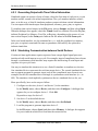
Simulating Communication between Multiple Devices . . . . . . . . . . . . . . . .
4.2
Developing Real-Time Applications . . . . . . . . . . . . . . . . . . . . . . . . . . . . . . . . . .
4.2.1
Generating Interrupts and Real-Time Stimuli of Pins . . . . . . . . . . . . . . . . . .
4.2.2
Exercising Peripherals . . . . . . . . . . . . . . . . . . . . . . . . . . . . . . . . . . . . . . . . . .
4.2.3
Generating Output with Time-Critical Information . . . . . . . . . . . . . . . . . . . .
4.2.4
Simulating Communication between Serial Devices . . . . . . . . . . . . . . . . . . .
4.3
Finding Well Hidden Bugs . . . . . . . . . . . . . . . . . . . . . . . . . . . . . . . . . . . . . . . . .
4.3.1
Setting Breakpoints on Memory . . . . . . . . . . . . . . . . . . . . . . . . . . . . . . . . . .
4.3.2
Setting Breakpoints on Registers . . . . . . . . . . . . . . . . . . . . . . . . . . . . . . . . . .
4-1
4-1
4-2
4-4
4-4
4-4
4-5
4-6
4-6
4-7
4-7
4-9
Chapter 5
Answers to Frequently Asked Questions
5.1
5.2
5.3
5.4
5.5
5.6
5.7
5.8
5.9
5.10
5.11
5.12
5.13
How do I customize Suite56 tools for my tasks? . . . . . . . . . . . . . . . . . . . . . . . .
I’m tired of initializing my development environment every time I start work.
Is there any way to save my development environment? . . . . . . . . . . . . . . .
I logged a sequence of commands to a command log file.
How do I run that sequence of commands again? . . . . . . . . . . . . . . . . . . . . .
I logged a sequence of commands to a command log file and tried to run it.
No luck. What should I do? . . . . . . . . . . . . . . . . . . . . . . . . . . . . . . . . . . . . . .
I’m having trouble debugging at low frequencies. . . . . . . . . . . . . . . . . . . . . . . .
How do I halt in mid-cycle in a Suite56 simulator? . . . . . . . . . . . . . . . . . . . . . .
Can I link my customized libraries to a Suite56 simulator? . . . . . . . . . . . . . . . .
How do I simulate input and output?. . . . . . . . . . . . . . . . . . . . . . . . . . . . . . . . . .
How do I plot memory use?. . . . . . . . . . . . . . . . . . . . . . . . . . . . . . . . . . . . . . . . .
How do I get a listing with cycle counts? . . . . . . . . . . . . . . . . . . . . . . . . . . . . . .
My program runs, but I want it to go faster. . . . . . . . . . . . . . . . . . . . . . . . . . . . .
My program runs, but it is too big. . . . . . . . . . . . . . . . . . . . . . . . . . . . . . . . . . . .
What does this error message mean?. . . . . . . . . . . . . . . . . . . . . . . . . . . . . . . . . .
5-1
5-2
5-3
5-3
5-3
5-4
5-5
5-5
5-5
5-6
5-6
5-7
5-7
Glossary
Index
Motorola
Table of Contents
v
vi
Suite56 DSP Tools User’s Manual
Motorola
List of Figures
1-1
Simple Code Development Cycle:
Compile, Link, Execute to Debug . . . . . . . . . . . . . . . . . . . . . . . . 1-1
1-2
Compiling by Default or with the Option -c . . . . . . . . . . . . . . . . . 1-2
1-3
Input and Output of the Assembler . . . . . . . . . . . . . . . . . . . . . . . 1-4
1-4
Input and Output of the Linker. . . . . . . . . . . . . . . . . . . . . . . . . . . 1-5
1-5
Typical Use of a Simulator in a Filtering Application . . . . . . . . . . 1-6
1-6
Graphic User Interface of the Simulator . . . . . . . . . . . . . . . . . . . 1-8
1-7
Text-Based Interface of the Simulator. . . . . . . . . . . . . . . . . . . . 1-10
1-8
Parts of the Hardware Debugger (ADS) . . . . . . . . . . . . . . . . . . 1-11
1-9
Graphic User Interface of the Hardware Debugger. . . . . . . . . . 1-13
2-1
Setting up a Suite56 ADS with its ADM. . . . . . . . . . . . . . . . . . . . 2-2
3-1
Setting a Software Breakpoint. . . . . . . . . . . . . . . . . . . . . . . . . . . 3-9
3-2
Clear Breakpoints Dialog Box . . . . . . . . . . . . . . . . . . . . . . . . . . 3-11
3-3
Setting a Hardware Breakpoint . . . . . . . . . . . . . . . . . . . . . . . . . 3-13
4-1
Connecting Non-JTAG Devices for Debugging. . . . . . . . . . . . . . 4-1
4-2
Connecting Devices through Their JTAG Interfaces for Debugging4-2
4-3
Dialogue Box to Set a Breakpoint in Memory . . . . . . . . . . . . . . . 4-9
Motorola
List of Figures
vii
viii
Suite56 DSP Tools User’s Manual
Motorola
List of Examples
2-1
2-2
2 -3
Start the Debugger . . . . . . . . . . . . . . . . . . . . . . . . . . . . . . . . . . . . . . . . . . 2-4
Test Commands for the Command Converter . . . . . . . . . . . . . . . . . . . . . 2-4
Test Commands for the Target Device . . . . . . . . . . . . . . . . . . . . . . . . . . . 2-5
2 -4
Setting Low Frequencies in Suite56 Tools . . . . . . . . . . . . . . . . . . . . . . . . 2-5
3 -1
Logging Commands to a File for Reuse . . . . . . . . . . . . . . . . . . . . . . . . . . 3-3
3 -2
A Sample C Program: ltp.c . . . . . . . . . . . . . . . . . . . . . . . . . . . . . . . . . . . . 3-7
3 -3
Defining a Watch List . . . . . . . . . . . . . . . . . . . . . . . . . . . . . . . . . . . . . . . 3-16
3 -4
Removing Items from a Watch List . . . . . . . . . . . . . . . . . . . . . . . . . . . . 3-16
3 -5
A Finite Impulse Response Filter in Assembly Code: fir.asm . . . . . . . . 3-20
3 -6
A Header File for the FIR Example: iodata.h . . . . . . . . . . . . . . . . . . . . . 3-21
3 -7
A C program That Calls Assembly Code . . . . . . . . . . . . . . . . . . . . . . . . 3-24
3 -8
An Assembly Routine Called by a C Program . . . . . . . . . . . . . . . . . . . . 3-25
3 -9
A Sample Assembly File for Memory Mapping: section_a.asm . . . . . . 3-25
3 -10
A Sample Assembly File for Memory Mapping: section_b.asm . . . . . . 3-25
3 -11
Assembling Two Relocatable Object Files. . . . . . . . . . . . . . . . . . . . . . . 3-26
3 -12
A Memory Control File: sec.ctl . . . . . . . . . . . . . . . . . . . . . . . . . . . . . . . 3-26
3 -13
Command to Link Memory Control File to Object Files . . . . . . . . . . . . 3-26
3 -14
A Memory Map File: out.map . . . . . . . . . . . . . . . . . . . . . . . . . . . . . . . . 3-27
5 -1
Setting Low Frequencies in Suite56 Tools . . . . . . . . . . . . . . . . . . . . . . . . 5-4
5 -2
Signature of dsp_execp . . . . . . . . . . . . . . . . . . . . . . . . . . . . . . . . . . . . . . . 5-4
5 -3
The Function dsp_exec . . . . . . . . . . . . . . . . . . . . . . . . . . . . . . . . . . . . . . . 5-4
Motorola
List of Examples
ix
x
Suite56 DSP Tools User’s Manual
Motorola
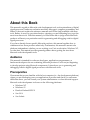
About this Book
This manual is a guide to Motorola code-development tools, such as simulators of digital
signal processors, hardware evaluation modules, debuggers, compilers, assemblers, and
linkers. It does not replace the reference manuals and on-line help available with these
tools. Rather, it serves as your introduction, orienting you and indicating how to get the
most from these tools. With this manual, you’ll be better able to judge which Motorola
products will meet your particular needs for generating and debugging code for digital
signal processors.
If you have already chosen specific Motorola products, this manual explains how to
combine and use those products effectively. Furthermore, this manual is meant to be
platform-independent; whether you are working on a Unix work station, Windows NT,
or other host, this manual provides general guidance about getting the most from
Motorola code-development tools.
Audience
This manual is intended for software developers, applications programmers, or
hardware developers who are evaluating Motorola products or who are just beginning
to develop projects using Motorola components. It introduces you to generating and
debugging code for digital signal processors with Motorola tools.
Prerequisites
We assume that you are familiar with the host computer (i.e., the development platform)
where you are developing your own application or product and that if you encounter
difficulties there, you can consult your system administrator or other technical support.
Motorola code-development tools run on the following platforms:
• Windows NT
• Windows 95
• Hewlett-Packard HP-UX
• Sun OS 4
• Sun Solaris
Motorola
About this Book
xi
We also assume that you are fluent in the programming language—whether C or
assembly language—for your project, and that if you have difficulties with it, you will
consult your favorite language manual. If you are developing your application in C, then
of course you need a C cross-compiler installed on your development system. (Section
1.1, “Compilers,” on page 1-2, offers more information about available C
cross-compilers.) Likewise, if you have decided to program in assembly language, then
you need an appropriate cross-assembler installed on your host. (Section 1.2,
“Assemblers,” on page 1-3, offers more information about available cross-assemblers.)
As you work, you will need the reference manual for your cross-compiler or assembler.
There is a specific manual for each of the Motorola cross-compilers; there is a single
manual to cover all the available Motorola assemblers. You can retrieve copies of those
manuals from the Motorola website:
http://www.motorola-dsp.com/documentation
Similarly, you can find documentation for Motorola digital signal processors, including
their technical data sheets, their family reference manuals, and their device-specific
reference or user’s manuals at the same website.
To download examples of code that appear in this manual, go to the following website:
http://www.motorola-dsp.com/documentation/downloadable
Organization
This manual is organized into several chapters.
• Chapter 1, “Selecting Tools,” covers possible configurations of Motorola tools and
devices.
• Chapter 2, “Testing Your Hardware Installation,” supplies trouble-shooting
guidelines in the unlikely event you encounter difficulty while installing
Motorola tools.
• Chapter 3, “Debugging C and Assembly Code,” walks you through both C and
assembly programs, showing you how to set break points; how to create watch
lists; how to integrate C with assembly programs in the same application; how to
use memory control and map files.
• Chapter 4, “Tips about Special Projects,” is based on information gleaned from
Motorola customers who have used these development tools successfully in their
own projects.
• Chapter 5, “Answers to Frequently Asked Questions,” collects handy information
to help you customize your development environment and to avoid known
pitfalls.
A glossary and an index complete the manual.
xii
DSP Tools User’s Manual
Motorola
Conventions
This manual uses the following notation conventions:
• Courier monospaced type indicates commands, command parameters, code,
expressions, data types, and directives.
• Curly brackets {} are used in two ways.
In the context of the syntax of commands (for example, in a reference manual),
they enclose a list of command parameters from which you must choose one; the
curly brackets are not part of the command; you do not need to enter the curly
brackets.
In the context of arguments passed to the Motorola simulator or Motorola ADS
debugger, they enclose a C expression for evaluation. In this context, you must
enter the curly brackets.
• Square brackets [] enclose optional command parameters; for example,
wait[count(seconds)] indicates that count is an optional parameter. The
square brackets themselves are not part of the command; you do not need to enter
them.
• A slash between items in a list of optional parameters indicates that only one item
from that list may be used as a parameter to that command; that is, the items are
alternatives to each other. For example, this command log [c/s/p] filename
indicates that log c filename is a valid command, that log s filename is a
valid command, but log c s filename is not a valid command.
• Commands can be abbreviated; in the reference manuals and in this manual, for
example, wait indicates that you can type w for the wait command.
• Ellipsis (that is, three consecutive periods) in a command indicate that you can
repeat the preceding field. For example, the command
save address_block . . . indicates that you can save more than one block
at a time.
• All source code examples are in C or assembly code.
Acronyms and Abbreviations
The following list defines the acronyms and abbreviations used in this document.
ADM
application development module (a board)
ADS
application development system (an ADM, a command converter,
host interface card, cables, and accompanying software)
DSP
digital signal processor
EPROM
erasable, programmable, read-only memory
EVM
evaluation module (a board)
FIR
finite impulse response (a type of filter)
Motorola
About this Book
xiii
GSM
global system for mobile communication
GUI
graphic user interface
IIR
infinite impulse response (a type of filter)
JTAG
Joint Test Action Group (an industry-wide consortium)
LTP
long-term predictor (an algorithm used in digital signal processing)
OnCE™
On-Chip Emulation (a protocol and circuitry comprising a
debugging module)
PROM
programmable, read-only memory
ROM
read-only memory
Bibliography
The following documents are available from the Motorola Literature Distribution Center
(LDC) or on the Motorola website: http://www.motorola-dsp.com/documentation.
Motorola DSP Application Development System (ADS) User’s Manual (DSPASDUM/D)
Motorola DSP Simulator Reference Manual (web only)
Motorola DSP56300 Family Optimizing C Compiler User’s Manual (and other
family-specific compiler manuals)
Motorola DSP Assembler Reference Manual (web only)
Motorola DSP Linker/Librarian Reference Manual (web only)
Motorola DSP56303 ADM Reference Manual (and other device-specific ADM manuals,
web only)
Motorola DSP56303 EVM Reference Manual (and other device-specific EVM manuals, web
only)
Motorola DSP56300 Family Manual (DSP56300FM/AD)
Motorola DSP56600 Family Manual (DSP56600FM/AD)
Motorola DSP56800 Family Manual (DSP56800FM/AD)
xiv
DSP Tools User’s Manual
Motorola
Chapter 1
Selecting Tools
This chapter explains which Motorola Suite56 tools will enable you to accomplish which
tasks; it describes the tools briefly and provides illustrations showing how to make the
tools work together as you generate and debug code for digital signal processors.
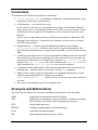
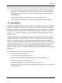
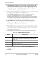
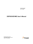
The simplest code-development cycle in digital signal processing begins, as in Figure 1-1,
when you compile a high-level program, link its object code to any libraries or other
object files you may need, and execute the results either in a Suite56 simulator or through
a Suite56 hardware debugger. Motorola’s Suite56 offers an entire toolset for such a cycle,
including a compiler, linker, simulator, and hardware debugger. Other companies, such as
Tasking Software BV, also provide a toolset for this cycle. Additionally, you can “mix and
match” tools from Motorola with other toolsets. This chapter offers recommendations
about selecting tools to meet your needs.
co m pile r
a sse m ble r
assem bler
lin ker
sim ulato r
h a rd w a re d e bug g e r
no longer AA1641
Figure 1-1. Simple Code Development Cycle: Compile, Link, Execute to Debug
Motorola
Selecting Tools
1-1
Compilers
1.1 Compilers
Motorola recommends purchase of the Tasking C compiler for the DSP56300 and
DSP56600 families of digital signal processors. Motorola markets the m568c C compiler
for the DSP56800 family. Alternatively, Motorola distributes enhanced versions of the
ANSI-compliant GNU C compiler. These compilers are specific to families of Motorola
devices; that is, the g563c is an optimizing C compiler for the DSP56300 family of
devices, and the g566c for the DSP56600 family. There is no GNU C Compiler for the
DSP56800 Family. From its website, Motorola distributes these enhanced, optimizing,
GNU C compilers along with device-specific utilities, such as preprocessors, to give you
greater control over the runtime environment. Each of those optimizing, family-specific
C compilers implements the C programming language according to ANSI X3.159-1989.
The Suite56 C preprocessor that Motorola distributes also conforms to an ANSI standard.
It facilitates inclusion of arbitrary text files, supports conditional compilation, allows
macro definition and expansion. In fact, as an independent program, the preprocessor may
be used as a general purpose macro preprocessor.
d efau lt co m pila tio n
co m piler
op tio n -c
linker
hardwa re de bugg er
sim u lato r
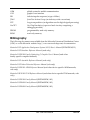
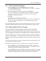
Figure 1-2. Compiling by Default or with the Option -c
By default, when you compile a C program with the Suite56 compiler, it silently calls the
assembler and then the linker to produce executable object code, as in Figure 1-2. If your
project can be contained in a straightforward C source file that does not require linking to
external libraries or other object files, then default compilation offers you a streamlined
path to project development. In contrast, if you choose the option -c, then the compiler
silently calls only the assembler, to produce object files that must be explicitly linked.
1-2
Suite56 DSP Tools User’s Manual
Motorola
Assemblers
This option to link explicitly is obviously a good choice under several different conditions:
•
if your project consists of many, large C source files; if those files are compiled
with option -c, then changes to one file will simply require recompilation of that
file and relinking to the others; you can save the time required to recompile the
unchanged files;
•
if your project consists of a mixture of C source and assembly code;
•
if your project needs to link to existing libraries or other object-code modules.
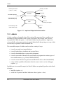
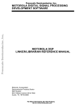
1.2 Assemblers
Each Motorola digital signal processor recognizes a set of machine instructions. A Suite56
assembler translates mnemonic operation codes (recognizable by humans) into machine
instructions recognized by a Motorola digital signal processor. An assembler also accepts
mnemonic directives indicating how it should behave. Suite56 assemblers, for example,
accept include directives, allowing you to put include files into applications based on
assembly code.
Suite56 assemblers understand algebraic expressions as arguments to directives and as
immediate operands in certain instructions. Suite56 assemblers also accept user-defined
macros, even nested macros, converting them into appropriate sequences of machine
instructions. Suite56 assemblers support conditional assembly, and they provide a suite of
transcendental functions (such as sine, cosine, natural logarithm) widely used in digital
signal processing. These features are documented in the Motorola DSP Assembler
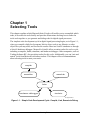
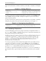
Reference Manual. Figure 1-3 on page 1-4 illustrates some of the features of these Suite56
assemblers.
An assembler can produce various kinds of output:
•
a relocatable object file (option -b)
•
a listing of the source program (option -l)
•
an object file with symbolic information from the source file (option -g)
•
verbose reports about its progress (option -v)
•
a report about loadtime and runtime memory use (option -mu)
•
an absolutely located object file or executable object file (option -a) or relocatable
overlays (default)
Motorola
Selecting Tools
1-3
Linkers
assembly code files
(*.asm)
assembly macro files
(*.mac, *.h, *.asm)
equate files
assembler
relocatable object file
(*.cln)
option -l
listings
(*.lst)
executable object file
COFF format (*.cld)
option -mu
linker
memory use reports
option -m
executable object file
COFF format (*.cld)
map file
(*.map)
Figure 1-3. Input and Output of the Assembler
1.3 Linkers
A linker combines relocatable object files (such as files generated by a compiler or an
assembler) or object modules (such as parts of a library) into a single, new, absolute
executable file. With the option -i, the Suite56 linker can also produce a single, new,
relocatable file; such output can then in turn be linked itself, thus giving you a way to link
incrementally to produce a final executable file.
The executable output of a linker can be used in a variety of ways:
•
it can be executed on a target platform;
•
it can be loaded into a simulator and executed there;
•
it can be downloaded into a system in development;
•
it can be converted to Motorola S-record format to program into various types of
non-volatile memory (e.g., Flash, EPROM, PROM);
•
it can be sent to Motorola to generate mask ROM for devices that include ROM;
•
it may include symbolic information from the source code to use in a debugger
(option -g).
In addition to its executable output, the Suite56 linker can optionally produce other kinds
of output:
1-4
•
map files (option -m);
•
sorted list of symbols and their load-time values (option -m also).
Suite56 DSP Tools User’s Manual
Motorola
Linkers
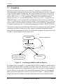
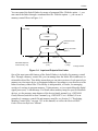
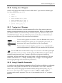
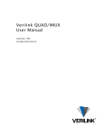
You can control the Suite56 linker by means of command files. With the option -f, you
can control the linker through a command-line file. With the option -r, you can use a
memory-control file as in Figure 1-4.
C source files
make utility
compiler
command line file
option -f
memory control file
option -r
linker
default
executable object file
COFF format (*.cld)
option -i
option -m
relocatable file
(*.cln)
map file
(*.map)
no longer AA164
Figure 1-4. Input and Output of the Linker
One of the most powerful features of the Suite56 linker is its facility for memory control
files. Through a memory control file, you can manage how the linker fills in addresses in
relocatable object files. This ability means that you can place sections of code precisely in
memory on your target device, at designated addresses according to your directives to the
linker in memory control files. This facility is indispensable, of course, for managing
overlays of sections in program memory, X data memory, or (on certain Motorola digital
signal processors) Y data memory. For details about memory maps for specific Motorola
devices, see the memory map chapters of the device family manual (e.g., DSP56300
Family Manual) and device user’s manual (e.g., DSP56307 User’s Manual). For an
example of a memory control file and memory map file, see Section 3.5, "Exploiting
Memory Control Files," on page 3-25 in this manual, as well as the Motorola DSP
Linker/Librarian Reference Manual.
Motorola
Selecting Tools
1-5
Simulators
1.4 Simulators
A Suite56 simulator is a software implementation of a hardware device, such as a digital
signal processor. As such, a simulator is advantageous in a number of ways:
•
Whereas hardware for code development may be costly or limited in number,
software simulators can serve any number of developers.
•
As software, a simulator may be more portable—in the sense of traveling from
office to home, for example—than comparable hardware for code development.
•
Simulators can be reset remotely, unlike hardware for code development. If you are
working remotely (from home, for example), a simulator reset is much less
cumbersome than a physical hardware reset.
•
Suite56 simulators also offer detailed profiles of code execution—profiles
unavailable through hardware for code development.
A Suite56 simulator exactly reproduces the following functions:
•
all core functions, including pipelining and exception processing;
•
most peripheral activity;
•
all internal and external memory access of a Motorola digital signal processor.
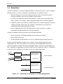
In short, Suite56 simulators enable you to evaluate a target digital signal processor
comprehensively. They also enable you to emulate your own algorithms entirely in
software and thus to evaluate how those algorithms behave with your target hardware. In
fact, evaluation of algorithms is one of the chief uses of a simulator. Figure 1-5 illustrates
a typical use of a simulator to emulate a device in an audio application.
icrophone
analog
A/D CODEC
digital
synchronous serial
interface (SSI) port
real-time application
analog
D/A CODEC
digital
Motorola dsp
speaker
simulated input file
synchronous serial
interface (SSI) port
simulated development
simulated output file
Suite56 dsp simulator
Figure 1-5. Typical Use of a Simulator in a Filtering Application
1-6
Suite56 DSP Tools User’s Manual
Motorola
Simulators
1.4.1 Data Streams and the Simulator
A simulator is also a reasonable choice when you frequently have to download very large
files that would be slow or cumbersome to download from a hardware debugger to a target
board. In fact, Suite56 simulators implement several types of data streams expressly for
such activity. The Motorola DSP Simulator Reference Manual documents these data
streams in Chapter 3, “Device I/O and Peripheral Simulation,” and Section 4.2.1,
"Generating Interrupts and Real-Time Stimuli of Pins," on page 4-4 in this manual offers
suggestions for using simulated data streams. These data streams facilitate various kinds
of data communication.
•
From a host to a single memory address to simulate the interface to custom
memory-mapped peripherals
•
From a host to a single memory address to bypass on-chip peripherals
•
To a host from a single memory address
•
From a host to a pin or a group of pins
•
To a host from a pin or a group of pins
•
From pin to pin on the same simulated device (Connect the pins by means of the
input command.)
•
From pin to pin on different simulated devices (Create up to 32 simulated digital
signal processors by means of the device command, and interconnect them by
means of the input command.)
•
From a memory address on one simulated device to a memory address on another
simulated device
Moreover, when you need to analyze internal workings of a target digital signal processor,
a simulator is a good choice because it allows you to control such internals as the
instruction pipeline—a facility generally hard to access through hardware. A simulator
also allows you to monitor program results without disturbing the internal instruction
pipeline.
Motorola
Selecting Tools
1-7
Simulators
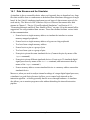
1.4.2 User Interfaces to the Simulator
The Suite56 simulator offers a graphic user interface with windows, menus, and online
help, as in Figure 1-6 on page 1-8. There are several ways of starting the Suite56
simulator. For example, if you are working on an NT platform and want to run the
simulator for the DSP56300 family, use one of the following alternatives:
•
Double-click its shortcut icon on your desktop.
•
From your Start menu, choose Programs; then choose Motorola DSP Software
Development Tools, and then choose DSP56300 Simulator.
•
From your Start menu, choose Run; then type gui56300 in the prompt window.
Help menu
Figure 1-6. Graphic User Interface of the Simulator
Suite56 simulators offer a text-based interface as well; it can be invoked interactively
through a console window or in batch mode through a command file. For example, to run
this interface of the simulator for the DSP56300 family, type the command sim56300 at a
command prompt of your operating system. Figure 1-7 on page 1-10 shows the text-based,
command-line interface of the simulator.
1-8
Suite56 DSP Tools User’s Manual
Motorola
Simulators
The Motorola DSP Simulator Reference Manual documents options available for both
interfaces of the simulator. In this manual, the answer to a frequently asked question offers
guidelines for customizing your interface to a Suite56 simulator (Section 5.1, "How do I
customize Suite56 tools for my tasks?," on page 5-1).
1.4.3 Debugging with the Simulator
The Suite56 simulator is well adapted to debug application code aimed at a digital signal
processor. To do so, you load object code—whether compiled C code or assembly
code—into the memory map of the simulated device. (The memory map of each simulated
device is documented in the memory map chapters of the device family manual (e.g.,
DSP56300 Family Manual) and device user’s manual (e.g., DSP56307 User’s Manual).)
The simulator then executes that code as the target device would do, displaying the
contents of device registers and memory locations, so you can see what is happening as
your application executes on your virtual device.
Besides seeing the contents of registers and memory locations, you can also change the
contents interactively through the simulator. Likewise, you can set both unconditional and
conditional breakpoints in code, at registers, and at memory locations. As a further aid to
debugging, the simulator also provides a single-line assembler. With the ASM command,
you can enter individual assembly instructions, which the simulator then executes. In other
words, using the ASM command, Suite56 simulators let you patch code as you are
debugging.
For details about displaying register contents, setting breakpoints, and using the single line
assembler, see the Motorola DSP Simulator Reference Manual and the online help
available with the simulator.
1.4.4 Online Help for the Simulator
Whether you are using the graphic or text-based interface, there is online help for each
command. Through the graphic user interface, of course, online help is available from the
Help menu on the menubar of the main window, as in Figure 1-6 on page 1-8.
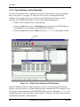
In the text-based, command-line interface (as in Figure 1-7), when you type a command
on the command line, then the syntax of that command appears automatically on the help
line. If you type a question mark after a command on the command line, then more help, in
addition to the command syntax, appears in the window.
Motorola
Selecting Tools
1-9
Hardware Debugger: ADS
session window
command line
help line
Figure 1-7. Text-Based Interface of the Simulator
1.5 Hardware Debugger: ADS
Like a simulator, a Suite56 hardware debugger, often referred to as the ADS or application
development system, allows you to evaluate a target digital signal processor
comprehensively and to evaluate how your algorithms behave with respect to your target
hardware.
To manage input and output, a Suite56 debugger offers highly advantageous facilities. An
ADS can, in fact, read data into the target device while running; it can also read data out of
a target device and into a host while running. That is, the hardware debugger behaves like
a device driving the host port to offer you much better control over simulated I/O.
A Suite56 ADS supports source-level symbolic debugging of both C and assembly
programs, and it offers debugging commands to support simultaneous development with
multiple devices.
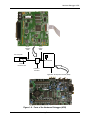
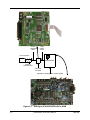
Figure 1-8 shows you the hardware components (host-bus interface card, interface cables,
command converter, and application development module) of a typical Suite56 ADS
hardware debugger. In addition to the visible components, the system also includes
software running on your development platform (the host computer) and in the command
converter.
1-10
Suite56 DSP Tools User’s Manual
Motorola
Hardware Debugger: ADS
37-pin
interface
cable
14-pin
ribbon
cable
host computer
Motorola DSP
host-bus
interface card
command
converter
application development module (ADM)
Figure 1-8. Parts of the Hardware Debugger (ADS)
Motorola
Selecting Tools
1-11
Hardware Debugger: ADS
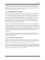
1.5.1 User Interfaces to the Debugger
The Suite56 debugger offers a graphic user interface with windows, menus, and online
help for interactive debugging, as in Figure 1-9 on page 1-13. There are several ways of
starting the Suite56 hardware debugger. For example, if you are working on an NT
platform and want to run the hardware debugger for the DSP56300 family, you use one of
the following alternatives:
•
Double-click its shortcut icon on your desktop.
•
From your Start menu, choose Programs; then choose Motorola DSP Software
Development Tools, and then choose DSP56300 Hardware Debugger.
•
From your Start menu, choose Run; then type gds56300 in the prompt window.
For customers who prefer command-line control, the Suite56 debugger offers a text-based
interface as well, invoked interactively through a console window or in batch mode
through a command file. For example, to run the text-based, command-line interface of
the hardware debugger for the DSP56300 family, you type the command ads56300 at
your operating system prompt.
The Motorola DSP ADS User’s Manual documents options available for both interfaces of
the debugger. Through those options, you can customize your development environment,
as we suggest in Section 3.1, "Initializing a Debugging Environment," on page 3-1.
1.5.2 Online Help for the Debugger
There is online help for each command and for each register through the Suite56 ADS
debugger. In the graphic user interface, of course, online help is available from the Help
menu on the menubar of the main window, as in Figure 1-9.
1-12
Suite56 DSP Tools User’s Manual
Motorola
Hardware Debugger: ADS
Help menu
Figure 1-9. Graphic User Interface of the Hardware Debugger
In the text-based, command-line interface, when you type a command on the command
line, then the syntax of that command appears automatically on the help line. If you type a
question mark after a command on the command line, then more help, in addition to the
command syntax, appears in the window.
Motorola
Selecting Tools
1-13
Hardware Debugger: ADS
1-14
Suite56 DSP Tools User’s Manual
Motorola
Chapter 2
Testing Your Hardware Installation
The manual for each Motorola Suite56 tool (such as a compiler, an assembler, the linker, a
simulator, a hardware debugger) includes a chapter explaining how to install that tool. The
manuals for platform-dependent tools, such as the Suite56 ADS hardware debugger, also
include an appendix of platform-specific details. This chapter assumes that you have
followed the steps outlined in those installation guides and offers simple tests to check
your installation. It begins with Figure 2-1, showing you how the Suite56 application
development module (ADM) is conventionally set up, as part of a Suite56 application
development system (ADS).
Motorola
Testing Your Hardware Installation
2-1
37-pin
interface
cable
14-pin
ribbon
cable
host computer
Motorola DSP
host-bus
interface card
command
converter
application development module (ADM)
Figure 2-1. Setting up a Suite56 ADS with its ADM
2-2
Suite56 DSP Tools User’s Manual
Motorola
Testing Your Installation of the Command Converter
2.1 Testing Your Installation of the Command Converter
If you have installed these Suite56 tools:
•
a hardware debugger, such as the ads56300 or gds56300,
•
a host-bus interface board, such as the 16-bit ISA bus for PC-compatible and
Hewlett-Packard workstations or the SBus for Sun and Sparc workstations,
•
corresponding software device drivers, and
•
the command converter,
to communicate with a target device, then we recommend that you perform either one the
following tests to determine whether your installation of the command converter was
successful.
2.1.1 Testing through the Graphic User Interface
To test your installation of the command converter through the graphic user interface to
your Suite56 tools, follow these steps:
1. Start the hardware debugger. If you are working on a PC-compatible machine
running Windows NT, for example, there are several different ways to start a
hardware debugger, such as gds56300.
— From your NT Start menu, select Programs, and then click on the item
Motorola DSP. (If the debugger you want to start does not appear as an item
among the Programs in your Start menu, then you may want to re-install your
debugger from your Motorola Suite56 Toolkit CD-ROM.)
— From your NT Start menu, select Run. When the command window opens,
type the command in Example 2-1.
— If you have created a shortcut icon of the Suite56 hardware debugger on your
desktop, then of course you simply click on that icon.
2. In the debugger, type the commands in Example 2-2 on page 2-4.
Motorola
Testing Your Hardware Installation
2-3
Testing Your Installation of the Command Converter
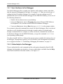
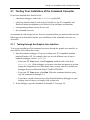
2.1.2 Testing through the Command-Line Interface
If you prefer the command-line interface to your Suite56 tools, then test your installation
of the command converter through the following steps:
1. Start the hardware debugger. For example, if you are using the debugger for the
DSP56300 family, type the command in Example 2-1. To start the hardware
debugger for other families, type the appropriate command, such as ads56800 for
the DSP56800 family or ads56600 for the DSP56600 family.
Example 2-1. Start the Debugger
C:\> ads56300
2. In the debugger, type the commands in Example 2-2.
Example 2-2. Test Commands for the Command Converter
> cforce r
> cdisplay x:0..10
2.1.3 Understanding the Test Results
In Example 2-2, the initial “c” in both commands indicates that the command is directed
to the command converter. The first debugger command, cforce r, resets the command
converter. If the debugger indicates an error, such as “unable to reset command
converter,” at that point, then you need to examine your installation of the parts
communicating with the command converter (i.e., the host-bus interface card and the
37-pin, parallel, interface cable).
The second command, cdisplay x:0..10, displays output. A display of any arbitrary
data is a good indication. However, if the debugger indicates an error, such as “unable to
read command converter memory,” then you need to examine your installation of the
command converter.
If both commands are successful, and you see a display of some arbitrary data, then you
can be sure your installation of the command converter is correct. That is, your
development host can communicate through the host-bus interface card, the Suite56
software tools, the software drivers, and the Suite56 command converter successfully, so
you can proceed to the next test.
2-4
Suite56 DSP Tools User’s Manual
Motorola
Testing a Low-Frequency Target Device
2.2 Testing Your Installation of a Target Board
If you have successfully completed the test in Section 2.1, "Testing Your Installation of
the Command Converter," and you have also connected a target device such as:
•
a Suite56 application development module (e.g., DSP563xx ADM),
•
a Suite56 evaluation module (e.g., DSP563xx EVM), or
•
your own target board,
then we recommend that you complete your installation test by typing the commands in
Example 2 -3. (The same commands work whether you are using the graphic user
interface or the command-line interface.)
Example 2 -3. Test Commands for the Target Device
> force s
> display
In contrast to the previous test, where both commands were prefixed by “c” to direct them
to the command converter, these commands are directed to the application development
module, the evaluation module, or your own target board. The first command, force s,
resets both the command converter and the target device. The second command displays
the contents of registers on the target device.
If both commands execute successfully and, as a consequence, you see register contents,
then you can be sure that your hardware installation is correct. If you encounter difficulty
at this point, then check whether the cable between the command converter and the target
device is working properly. If your cable is sound and your target device is a Suite56
product (e.g., Suite56 ADM or EVM), then contact your Motorola distributor for help in
determining whether your target board is defective and requires replacement.
2.3 Testing a Low-Frequency Target Device
For any low-frequency target device (i.e., less than 2MHz), you must set the command
converter and the Suite56 ADS debugger software to the proper serial clock frequency. To
do so, use the host command with the option clock followed by the frequency, as in
Example 2 -4.
The default radix of the Suite56 ADS debugger is hexadecimal. Consequently, to express
a frequency in decimal digits, we prefix it by this character: ‘.
Example 2 -4. Setting Low Frequencies in Suite56 Tools
> host clock ‘32
> host clock $32
Motorola
; sets the frequency to 32 kHz
; sets the frequency to 50 kHz
Testing Your Hardware Installation
2-5
Choosing a Connector for the EVM Power Supply
2.4 Choosing a Connector for the EVM Power Supply
Most Suite56 evaluation modules have a 2.1 millimeter receptacle to connect the external
power supply. Modules to support the DSP56800 family, however, are exceptional in this
respect: they have a 2.5 mm receptacle. A 2.5 mm connector will connect all modules, but
the recommended 2.1 mm connector for the 2.1 mm modules and a 2.5 mm connector for
the 2.5 mm modules are recommended to provide a secure power connection.
2-6
Suite56 DSP Tools User’s Manual
Motorola
Chapter 3
Debugging C and Assembly Code
This chapter walks you through sample programs in both C and assembly language to
highlight the debugging facilities in Suite56 tools, particularly the hardware debugger
(such as ads56800 or gds56300) and the simulator (such as sim56600 or gui56300).
The interfaces—both graphic and text-based—to the Suite56 simulator were deliberately
designed to be as similar as possible to those of the Suite56 ADS debugger. You can use
one very much as you use the other. Consequently, throughout this chapter, we will refer
to the graphic user interface and the text-based interface without distinguishing the
simulator from the Suite56 hardware debugger.
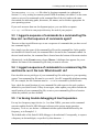
3.1 Initializing a Debugging Environment
There are many ways to customize your debugging environment, whether you use the
graphic user interface or the text-based, command-line interface. The following sections
outline those possibilities. For more detail about each topic, see the Motorola ADS User’s
Manual, particularly Chapter 3 about commands and Chapter 4 about the graphic user
interface, or the Motorola DSP Simulator Reference Manual, Chapter 9, about its graphic
user interface.
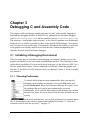
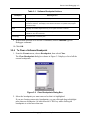
3.1.1 Choosing Preferences
To control which windows open automatically when you start the
debugger, in the graphic user interface, choose the File menu, and
choose Preferences. When the Preferences dialogue box opens, select
the windows that you want to open automatically at start up.
Additionally, if you click the Font button in that dialogue box, another
dialogue box opens for you to choose from the fonts available on your
system.
In the text-based interface, you set your preferences in a resource macro
file, as documented in the reference manual and explained in Section 5.1, "How do I
customize Suite56 tools for my tasks?," on page 5-1.
Motorola
Debugging C and Assembly Code
3-1
Initializing a Debugging Environment
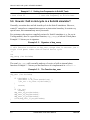
3.1.2 Defining Paths and Working Directories
A Suite56 tool, by default, looks for input files and places output files in the current
working directory. It can also redirect its search for files and its output to other specified
directories by means of a path. For every target device, the debugger can maintain a
distinct path, so you can organize input and output files for each target device separately.
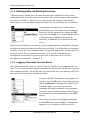
In the graphic user interface, to set the current
working directory and to define a path to alternate
directories for the current device, choose the File
menu, and select Path. You can then Set the current
working directory, Add other directories as
alternates, or Clear the list of directories for that
device.
In the text-based interface, you specify a current working directory and paths to alternate
directories through environment variables that you define. You define those environment
variables “on the fly” in a command window of your operating system, or alternatively in
a resource macro file, as explained in Section 5.2, "I’m tired of initializing my
development environment every time I start work. Is there any way to save my
development environment?," on page 5-2.
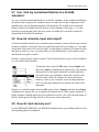
3.1.3 Logging Commands for Later Reuse
One of the most useful features of a Suite56 tool is its ability to log commands that you
issue. You can then save those logged commands in a file and reuse the file later to repeat
that command sequence. The log file that you create in this way is an ordinary ASCII text
file; you can edit it with your favorite text editor.
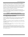
To create a log file of commands, in the graphic user
interface, from the File menu, choose Log, and then
choose Commands. A dialogue box opens for you
to indicate where you want to save the file
containing the logged commands. Any commands
you issue to the tool after that point will be logged
in that file to be saved automatically as executable
macros.
Later, when you want to stop logging commands,
from the File menu, choose Close. A dialogue box
appears for you to indicate which log to close.
3-2
Suite56 DSP Tools User’s Manual
Motorola
Initializing a Debugging Environment
Anytime you want to repeat that sequence of logged commands, from the File menu,
choose Macro. A dialogue box appears for you to indicate which file you want to execute.
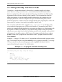
From the text-based, command-line interface, you can also save a sequence of commands
in a log file. You type the log command with two parameters: the option “c” to indicate
that you want to log only commands and the argument of a file name for the log file. With
a third option, you can also indicate whether you want to overwrite an existing file or
append new commands to an existing file, as in Example 3 -1.
To reuse such a command log file later, simply type the name of the log file on the
command line. (In the graphic user interface, the command line is located in the Command
window.) If you have difficulty with this step, check the answers to the FAQs about
command log files on page 5-3.
Example 3 -1. Logging Commands to a File for Reuse
> log c mycommands.cmd -a ; appends commands to mycommands.cmd
> log c mycommands.cmd -o ; overwrites mycommands.cmd with new commands
3.1.4 Logging a Session for Later Review
In addition to logging commands for later reuse, you can also log the entire contents of a
session. You might want to log the contents of a session for review later. You would not
execute a session log file, as it contains displayed data in addition to executable
commands.
To log a session in the graphic user interface, from the File menu, choose Log, and then
select Session. A dialogue box appears for you to indicate where you want to save the file
containing the session.
To stop logging a session, from the File menu, choose Close. A dialogue box appears for
you to indicate which log to close.
From the text-based, command-line interface, you can also save a session in a log file.
Type the log command with the option s (to indicate that you want to log a session) and
with the optional argument of a file name for the log file. With a third option, you can also
indicate whether you want to overwrite an existing file (option -o) or append new contents
to an existing file (option -a).
Motorola
Debugging C and Assembly Code
3-3
Initializing a Debugging Environment
3.1.5 Setting the Radix
Whether you are using the graphic user interface or the text-based interface, you can set
the radix for the display of the contents of registers before you display them. (The radix is
the basis for computing the value of digits as numbers. For example, the digits 32 in
decimal radix represent the value thirty-two and in hexadecimal radix, they represent
fifty.) In the Suite56 ADS, the default radix for the display of register contents is
hexadecimal. You set the default display radix to another base in the graphic user interface
from the Modify menu by choosing Radix. In the text-based interface, type the command
radix followed by the option to indicate the base you prefer (b for binary, d for decimal,
f for floating-point, h for hexadecimal).
When you enter data by typing , you can control its
radix (regardless of the default display radix) by
preceding it with a radix indicator:
•$ for hexadecimal
•‘ for decimal
•% for binary
3.1.6 Displaying Registers
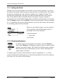
To display registers in the graphic user interface, from the Windows
menu, choose Register. A dialogue box appears for you to indicate which
registers you want to display. The Suite56 tool will then open a window,
labeled with the device and registers you have chosen, and display the
register names and values.
To display registers in the text-based interface, type the command display with no
options to display all enabled registers, or with option on followed by the list of registers
you want to see for a more selective display.
3-4
Suite56 DSP Tools User’s Manual
Motorola
Source-Level Debugging in C
3.1.7 Displaying Memory
To display blocks of memory in the graphic user interface, from the
Windows menu, choose Memory. A dialogue box appears for you to
indicate which parts of memory you want to display. (The parts available
for display vary according to the target device.) The Suite56 tool will then
open a window, labeled with the device and memory blocks you have
chosen, and display the block names and values. That window is interactive: you can both
see and modify memory contents there.
To display memory in the text-based interface, type the command display with no
options to display all enabled memory blocks, or with option on followed by the list of
memory blocks you want to see for a more selective display.
3.2 Source-Level Debugging in C
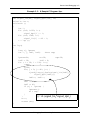
The C code in Example 3 -2 on page 3-7 implements a long-term predictor (LTP). This
type of code often appears in such applications as GSM vocoders and other voice
compression algorithms.
The routine main initializes two input buffers and then invokes the routine ltp. This
routine consists of an internal and external loop, which together compute a sum of
products calculated from elements of the two input arrays. In other words, ltp
implements a convolution. To do so, it uses these features:
•
The two arrays, signal_lin[] and signal_dpri[], are vectors of fractions.
•
Fractional multiplication is performed by result = lmult (inp1, inp2).
•
Fractional addition is performed by result = add_long (inp1, inp2).
With this example, we will highlight these debugging tasks: setting breakpoints and using
the go command effectively; defining a watch list; tracing; evaluating C expressions
(Don’t forget the curly brackets!); and casting.
Note:
Motorola
The C code in Example 3 -2 will not actually link successfully. It lacks the
definition of two C library routines, add_long(); and lmult();. Because
both of those routines are platform-dependent, in a linkable example, we use
#define for those definitions.
Debugging C and Assembly Code
3-5
Source-Level Debugging in C
3.2.1 Compiling to Debug
When you are preparing to debug a C program with Suite56 tools, you must compile the
program in debug mode with debugging symbols to retain information useful for
debugging in the executable code. The compiler option for debug mode is -g if you are
using a Suite56 C compiler, such as g563c for the DSP56300 family of devices or g566c
for the DSP56600 family.
3-6
Suite56 DSP Tools User’s Manual
Motorola
Source-Level Debugging in C
Example 3 -2. A Sample C Program: ltp.c
int signal_lin[40], signal_dpri[120], nc;
volatile int c;
void main ()
{
int i;
for (i=0; i<120; i++)
signal_dpri[i] = i;
for (i=0; i<40; i++)
signal_lin[i] = 40 - i;
c = ltp ();
}
int ltp()
{
long rj, lparam;
int i, j, ind1, ind2;
short tmp;
lparam=0L;
nc=39;
tmp=38;
ind2 = 39;
ind1 = 0;
for ( i = 39; i < 120; i++){
++tmp;
rj=0L;
for( j = 0; j< 40; j++) {
rj=add_long(rj,lmult(signal_lin[ind1],
signal_dpri[ind2]));
ind1++; ind2--;
}
ind1 -= 40;
ind2 += 41;
if (rj > lparam) {
lparam=rj;
nc = tmp;
}
}
rj = (signal_lini*signal_dprij)
nc++;
return (nc);
Σ
}
Motorola
Debugging C and Assembly Code
3-7
Source-Level Debugging in C
3.2.2 About Software Breakpoints in a C Program
This section discusses software breakpoints in debugging a C program. For details about
hardware breakpoints, see the family reference manual (e.g., Motorola DSP56600 Family
Manual) and the device manual (e.g., Motorola DSP56602 User’s Manual), particularly
chapters about the OnCE module and programming practices, for your target device.
Section 4.3, "Finding Well Hidden Bugs," on page 4-7, also offers guidance about
hardware breakpoints.
Software breakpoints are used to specify that a particular action be taken whenever a
certain condition is met. In this way, software breakpoints are very similar to hardware
breakpoints. However, software breakpoints are more limited than hardware breakpoints
in that:
•
software breakpoints can only be set on the first word of an instruction (they cannot
be set to detect the access of registers or data memory)
•
software breakpoints must be set in RAM (they cannot be set in ROM)
Despite the above limitations, it is recommended that you use software breakpoints
instead of hardware breakpoints whenever possible. Why? Because, effectively only one
hardware breakpoint can be set at a time whereas a virtually unlimited number of software
breakpoints can be set.
Software breakpoints can have several different effects. How you set the breakpoint
depends in part on the effects that you want to achieve:
•
A breakpoint causes execution of a program to halt and control of execution to
return to the user. This kind of breakpoint is known as a halt breakpoint.
•
In addition to halting, a breakpoint can also increment a counter so you can see how
often a piece of code has been executed.
•
In addition to halting, a breakpoint can also write to a Session window, so you can
see whether a piece of code has been executed.
•
A breakpoint may also be set in the program data so that as specific memory
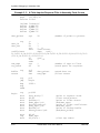
locations or registers are accessed, the break occurs. Section 4.3, "Finding Well
Hidden Bugs," on page 4-7, explains more about those breakpoints.
Regardless of how you set them, breakpoints are numbered, so that you can refer to them
as you watch them, disable them (i.e., turn them off), reenable them (i.e., turn them on
again), or direct execution to continue until it reaches a particular breakpoint. Moreover,
you can set more than one breakpoint at the same place to achieve more than one effect
(e.g., concurrently halt, increment a counter, write to the Session window, and execute a
user-defined routine).
3-8
Suite56 DSP Tools User’s Manual
Motorola
Source-Level Debugging in C
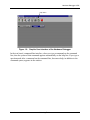
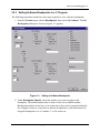
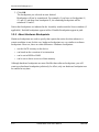
3.2.3 Setting Software Breakpoints in a C Program
The following procedure details the exact steps required to set a software breaktpoint.
1. From the Execute menu, choose Breakpoints, then select Set Software. The Set
Breakpoints dialog box shown in Figure 3-1 appears.
Figure 3-1. Setting a Software Breakpoint
2. Under Breakpoint Number select the number you want to assign to this
breakpoint. The default number that is shown is the next available number.
Breakpoint numbers do not have to be consecutive, they can be assigned arbitrarily.
For example, it may be convenient to allocate breakpoints so that one function is
assigned breakpoints 1 to 10, another 11 to 20, and so on.
Motorola
Debugging C and Assembly Code
3-9
Source-Level Debugging in C
3. Under Count secify how many times the Debugger should encounter the
breakpoint before performing the action. For example, if you set the count to 3, the
breakpoint will be triggered the third time that the breakpoint is encountered. Real
time execution will be affected if you set the count to more than one.
4. If you have assigned an input file, you can mark EOF. The breakpoint will be acted
upon when the input file reaches an end-of-file. If you have marked EOF, under
Input File Number select the number of the input file. The input file number is the
number that you designated when you assigned the input file.
5. Under Type select the type of software breakpoint to set. If you select al, the
breakpoint will always be acted upon. Breakpoint types other than al are
conditional and device specific.
6. Under Address, type the address where you want the breakpoint to be set. For
example, to set a breakpoint at address $103 in p memory, type: p:$103
Note:
This address must be the first word of an instruction.
Note:
If you have set the breakpoint type (in step 5) to a conditional breakpoint (that
is, any type other than al), the breakpoint can only be set to an address which
contains a nop. Setting the breakpoint to an address which contains any other
opcode will cause your program to execute incorrectly.
7. Under Expression you can type an expression. The expression will be evaluated
when the address you specified is reached. If the expression is true, the breakpoint
will be triggered. If the expression is false, no action is taken and program
execution continues. Be aware that a side effect of evaluating an expression
(whether it is true or false) is that the program will not be executed in real time.
8. Under Action select what action is taken when the breakpoint is encountered:
3-10
Suite56 DSP Tools User’s Manual
Motorola
Source-Level Debugging in C
Table 3-1. Software Breakpoint Actions
Breakpoint
Resulting Action
Halt
Stops program execution when the breakpoint is encountered.
Note
Displays the breakpoint expression in the Session window each time it is true. Program
execution continues. The display in the Session window is not updated until program
execution stops.
Show
Displays the enabled register/memory set. Program execution continues.
Command
Executes a Debugger command at the breakpoint. Device execution commands, such as
TRACE or GO, will not execute.
Increment[n]
Increments the n counter by one.
9. If the action specified is to execute a command, under Command type the
Debugger command.
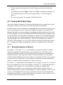
10. Click OK.
3.2.4 To Clear a Software Breakpoint
1. From the Execute menu, choose Breakpoints, then select Clear.
The Clear Breakpoints dialog box shown in Figure 3-2 displays a list of all the
current breakpoints.
Figure 3-2. Clear Breakpoints Dialog Box
2. Select the breakpoint you want removed so that it is highlighted.
If you are clearing consecutive breakpoints, you can click and drag to highlight
more than one breakpoint. Or hold down the CTRL key while clicking on
breakpoints to select more than one.
Motorola
Debugging C and Assembly Code
3-11
Source-Level Debugging in C
3. Click OK.
The breakpoints you selected are now deleted.
Breakpoints will not be renumbered. For example, if you have set breakpoints #1,
#2, and #3, and then clear breakpoint #2, the remaining breakpoints will be
numbered #1 and #3.
Notice that breakpoints are indicated in the Assembly window and the Source window (if
applicable). Enabled breakpoints appear in blue. Disabled breakpoints appear in pink.
3.2.5 About Hardware Breakpoints
Hardware breakpoints are used to specify that a particular action be taken whenever a
certain condition is met. In this way, hardware breakpoints are very similar to software
breakpoints. However, there are some differences. Hardware breakpoints:
•
use the OnCE circuitry on the device
•
can break on the execution of an instruction
•
can be set in ROM or RAM
•
can be set to detect an access of data memory
Although hardware breakpoints are more flexible than software breakpoints, you will
want to use hardware breakpoints judiciously. In effect, only one hardware breakpoint can
be enabled at any time.
3-12
Suite56 DSP Tools User’s Manual
Motorola
Source-Level Debugging in C
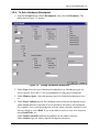
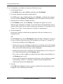
3.2.6 To Set a Hardware Breakpoint
1. From the Execute menu, choose Breakpoints, then select Set Hardware. The
dialog box in Figure 3-3 appears.
Figure 3-3. Setting a Hardware Breakpoint
2. Under Type select the type of hardware breakpoint to set. Breakpoint types are
device specific. See Table 3-2 for an explanation of each type of breakpoint.
3. Under Memory Space, select the memory space in which the breakpoint is to be
set.
4. Under First Condition specify the conditions under which the breakpoint occurs.
Under Access indicate what kind of access should be detected by the breakpoint.
For example, if you want the breakpoint to detect when a memory location is read
but not written to, select Read. If you want either a read or a write to be detected,
chose Read/Write, etc.
Under Address Qualifier indicate the qualifier for the address location.
Under Address type the address that the breakpoint references.
Motorola
Debugging C and Assembly Code
3-13
Source-Level Debugging in C
5. Under Option, indicate whether a second condition should be considered. And
indicates that both conditions must be met to trigger the breakpoint. Or indicates
that either condition can be met. Then indicates that the First Condition must be
satisfied followed by the Second Condition. Only indicates that only the first
condition must be met to trigger the breakpoint.
6. Under Second Condition specify the conditions for the second condition. This will
only apply if you have indicated so under Option in step 5.
7. Under Breakpoint Number select the number you want to assign to this
breakpoint. The default number shown is the next available number.
Breakpoint numbers do not have to be consecutive, they can be assigned arbitrarily.
For example, it may be convenient to allocate breakpoints so that one function is
assigned breakpoints 1 to 10, another uses 11 to 20, and so on.
8. Under Count specify how many times the Debugger should encounter the
breakpoint before stopping. For example, if you set the count to 3, the breakpoint
will be triggered the third time that the breakpoint is encountered.
Specifying a count will not affect real time execution.
9. Under Expression you can type an expression. The expression will be evaluated
when the first (and second) condition you specified is satisfied. If the expression is
true, the breakpoint will be triggered. If the expression is false, no action is taken
and program execution continues.
10. Under Action select what action is taken when the breakpoint is encountered:
Table 3-2. Hardware Breakpoint Actions
Breakpoint
Resulting Action
Halt
Stops program execution when the breakpoint is encountered.
Note
Displays the breakpoint expression in the Session window each time it is true. Program
execution continues. The display in the Session window is not updated until program
execution stops.
Show
Displays the enabled register/memory set. Program execution continues.
Command
Executes a Debugger command at the breakpoint. Device execution commands, such
as TRACE or GO, will not execute.
Increment[n]
Increments the n counter by one.
11. If the action specified is to execute a command, under Command type the
Debugger command.
12. Click OK.
3-14
Suite56 DSP Tools User’s Manual
Motorola
Source-Level Debugging in C
3.2.7 To Clear a Hardware Breakpoint
1. From the Execute menu, choose Breakpoints, then select Clear.
The Clear Breakpoints dialog box, shown in Figure 3-2 on page 3-11, displays a
list of all the current breakpoints.
2. Select the breakpoint you want removed so that it is highlighted.
If you are clearing consecutive breakpoints you can click and drag to highlight
more than one breakpoint. Or hold down the CTRL key while clicking on
breakpoints to select more than one.
3. Click OK.
The breakpoints you selected are now deleted.
Breakpoints will not be renumbered. For example, if you have set breakpoints #1,
#2, and #3, and then clear breakpoint #2, the remaining breakpoints will be
numbered #1 and #3.
Notice that breakpoints are indicated in the Assembly window and the Source window (if
applicable). Enabled breakpoints appear in blue. Disabled breakpoints appear in pink.
3.2.8 Defining a Watch List for a C Program
A watch list consists of C expressions, registers, memory locations, and general
expressions that will be displayed throughout a trace and each time you encounter a
breakpoint. In other words, a watch list consists of the items you want “to keep an eye on”
as you are debugging. You define the list by adding items to it or taking items off the list.
One note of caution: when you add a C expression to a watch list, you must enclose the C
expression in curly brackets, {}. In general, when you enter C expressions in a Suite56
simulator or Suite56 ADS hardware debugger, you must enclose the C expression in curly
brackets.
A watch list is device-specific; if you are working with more than one target device, then
you can define more than one watch list.
In the graphic user interface, there are two different ways to add items to a watch list:
•
From the Display menu, choose Watch, and then select Add. A dialogue box
appears for you to enter the register, memory location, or C expression to watch.
You also choose the radix for the item in that window.
•
From the Windows menu, choose Watch. A dialogue box appears for you to enter
the register, memory location, or C expression to watch. You also choose the radix
for the item and indicate which window to associate with the watched item.
Motorola
Debugging C and Assembly Code
3-15
Source-Level Debugging in C
In the text-based interface, to define a watch list, use the watch command, as in Example
3 -3.
Example 3 -3. Defining a Watch List
>
>
>
>
watch r0
watch x:0
watch {signal_lin[ind1]}
watch
; adds the register to the watch list
; adds memory location to the watch list
; adds item of array to the watch list
; displays the current watch list
To remove an item from a watch list, in the graphic user interface, from the Display menu,
choose Watch, and then select Off. A dialogue box appears for you to select items to
remove from the watch list.
To remove an item from a watch list in the text-based interface, use the watch command
followed by the number of the watch item and the off option, as in Example 3 -4
Example 3 -4. Removing Items from a Watch List
> watch
> watch off
> watch #1 off
; displays current watch list to show item numbers
; removes all items from the watch list
; removes first item from the watch list
3.2.9 Evaluating C Expressions
As you are debugging, you can use any valid C expression as an argument to the break,
evaluate, type, and watch commands. When you use C expressions as arguments, you
must enclose the expression in curly brackets, {}.
In addition to the usual C operators, Suite56 tools offer two additional operators for use in
C expressions. The operator “#” makes it easier to refer to elements of an array. The
operator “$” enables you to refer to registers directly in expressions. (This use of the
operator “$” in C expressions within curly brackets differs from its use to set a
hexadecimal radix in assembly code.)
To see how an expression will be evaluated (for example, before you actually use it in a
command), in the graphic user interface, from the Display menu, choose Evaluate. A
dialogue box opens for you to type the expression to evaluate. In the text-based interface,
type the evaluate command followed by the expression you want to see.
To evaluate a C expression in the graphic user interface (i.e., to use it in a command), in
the Command window, type the expression enclosed in curly brackets on the command
line.
3-16
Suite56 DSP Tools User’s Manual
Motorola
Source-Level Debugging in C
3.2.10 Casting in a C Program
Suite56 tools support these kinds of casts for both basic C types and user-defined types
(i.e., those defined by typedef):
•
•
•
•
•
•
(type)
(type *)
(enum enumeration_tag)
(enum enumeration_tag *)
(struct structure_tag *)
(union union_tag *)
3.2.11 Tracing in a C Program
Suite56 tools offer tracing so you can continuously see the values in any registers or
memory locations that interest you as your program executes. Before you begin tracing,
you indicate whether you want to trace by execution cycles, by lines of C code, or by
assembled instructions. You also indicate how many cycles, lines, or instructions you
want to trace and whether to halt execution for breakpoints.
To trace in the graphic user interface, from the Execute menu, choose
Trace. A dialogue box appears for you to indicate cycles, lines, or
instructions, how many, and whether to halt at breakpoints.
To trace in the text-based interface, type the trace command with
options and parameters to indicate how you want the trace to proceed.
Use the Next button on the toolbar to skip over subroutine calls and step through
execution routine by routine. In other words, the Next button recognizes which
assembly instructions make up a C routine, effectively executes each routine to
completion, and then steps from that executed routine to the first instruction of the next
routine. (See Section 3.3.2, "Tracing Assembly Code," on page 3-23, for suggestions
about stepping through code instruction by instruction.)
3.2.12 Using C-Specific Commands
As you have seen, the debugging commands in Suite56 tools are available to you through
menu items in the graphic user interface and as commands to enter in the Command
window. Most of the debugging commands available through Suite56 tools—break,
evaluate, finish, go, next, step, trace, until, watch—apply to both C
programs and assembly programs. There are a few commands specific to C programs,
however.
Motorola
Debugging C and Assembly Code
3-17
Source-Level Debugging in C
These are the C-specific debugging commands:
•
down moves down the C function call stack. In the graphic user interface, from the
Modify menu, choose Down.
•
frame designates the current frame in the C function call stack. (The current frame
determines the scope for evaluation.) In the graphic user interface, from the
Display menu, choose Call Stack.
•
redirect redirects standard input (stdin) and standard output (stdout and
stderr). With it, you can make stdin take data from a file and send standard
output to files. In the graphic user interface, from the File menu, choose
I/O Redirect.
•
streams enables and disables input and output on the host side for C programs. In
the graphic user interface, from the File menu, choose I/O Streams.
•
type accepts a C expression enclosed in curly brackets {} as its argument and
displays the type of the return value of that expression. In the graphic user
interface, from the Display menu, choose Type.
•
up moves up the C function call stack. In the graphic user interface, from the
Modify menu, choose Up.
•
where displays the C function call stack. With no options, it displays the entire
stack. With a numeric option, you tell it how many frames of the stack to display.
In the graphic user interface, from the Display menu, choose Call Stack.
3.2.13 Profiling a C Program
After you have loaded your C program into a Suite56 simulator, you can profile the
program as it executes. The profiler counts the number of instructions of each type in the
program, calculates their percentage of the program, and analyzes the number and type of
instructions actually executed. It also analyzes addressing modes used with respect to
instruction types. It assesses interaction between subroutines during execution. It
computes the runtime of the program execution in terms of clock cycles. Finally, it places
its results in two files; one file, with the extension .log, is an ordinary ASCII text file,
formatted in 80 columns; the other, with the extension .ps, contains a PostScript version
of the same results for nicely formatted output from a PostScript printer with appropriate
fonts. Only the Suite56 simulator offers these profiling facilities.
To profile your program, in the graphic user interface of the simulator, first load both
memory and symbols. Next, from the File menu, choose Log, and then select Profile. A
dialogue box appears for you to indicate the name and location of the log file to contain
the profile that the tool will generate. Profiling will continue until you click the File menu
3-18
Suite56 DSP Tools User’s Manual
Motorola
Symbolic Debugging in Assembly Code
again and choose Close. A dialogue box opens for you to indicate that you want to close
the Profile log file. Closing that file will end that profile.
In the text-based interface of the simulator, first load your executable program, both
symbols and memory. Then use the log command with two arguments: the option p to
indicate profile and a name for the profile log file. A third option indicates whether to
append the profile to an existing file (option -a), to overwrite any existing file of the same
name (option -o), or to cancel the profile if a file of the same name already exists
(option -c). To end a profile, use the log command with the option off.
3.3 Symbolic Debugging in Assembly Code
The assembly code in Example 3 -5 implements a basic finite impulse response filter. FIR
filters are widely used in digital signal processing. The include file, iodata.h, in
Example 3 -6 on page 3-21 saves registers onto a stack and restores them from that stack.
It also uses Suite56 debugging facilities (e.g., the debug instruction) to manage simulated
input. For more about simulated input, see Section 4.2.1, "Generating Interrupts and
Real-Time Stimuli of Pins," on page 4-4, and Section 5.8, "How do I simulate input and
output?," on page 5-5.
Motorola
Debugging C and Assembly Code
3-19
Symbolic Debugging in Assembly Code
Example 3 -5. A Finite Impulse Response Filter in Assembly Code: fir.asm
opt
cex,mex,cre,cc,mu
page
132,66,0,10
section filter
include
define
define
define
define
"iodata.h"
P_MEM "0"
X_MEM "1"
Y_MEM "2"
L_MEM "3"
data_points
equ
org
data_in
data_out
y:
ds
ds
set
xdef
20
;number of points to process
1
1
i
0
coefficients
coefficients
dupa
coef,21.0/231.0,14.0/231.0,39.0/231.0,54.0/231.0,59.0/231.0,54.0/231.0,39.0
/231.0,14.0/231.0,-21.0/231.0
dc
coef
set
i
i+1
endm
num_taps
equ
i
;number of taps in filter
reg_stack
ds
10
;stack space for registers
org
buffer
states
x:0
dsm
dsm
data_points
num_taps
;saved data out
;filter states
org
jmp
p:0
begin
dup
nop
endm
$100-*
org
p:$100
move
move
move
move
move
move
move
move
#reg_stack,r7
#0,sp
#states,r1
#num_taps-1,m1
#coefficients,r5
#num_taps-1,m5
#buffer,r6
#data_points-1,m6
;point to register stack
;clear stack pointer
;point to filter states
;mod(num_taps)
;point to filter coefficients
;mod(num_taps)
;point to storage buffer
;mod(data_points)
move
rep
move
#0,x0
#num_taps
x0,x:(r1)+
;clear tap states
begin
3-20
Suite56 DSP Tools User’s Manual
Motorola
Symbolic Debugging in Assembly Code
rep
move
#data_points
x0,x:(r6)+
;clear data points
.loop
do
#data_points,end_fir
;one loop for each tap
IODATA
move
input_data,1,1,Y_MEM,data_in
y:data_in,x0
jsr
fir_filter
move
IODATA
a,y:data_out
output_data,1,1,Y_MEM,data_out
;output sample
;write data to ADS
move
a,x:(r6)+
;save data
a x0,x:(r1)+ y:(r5)+,y0
#num_taps-1
x0,y0,a x:(r1)+,x0 y:(r5)+,y0
x0,y0,a (r1)-
;save first state
;read data from ADS
;get sample
end_fir
.endl
fir_filter
clr
rep
mac
macr
rts
endsec
end
Example 3 -6. A Header File for the FIR Example: iodata.h
IODATA
macro label,filenumber,count,memoryspace,address
move
x0, y:(r7)+
; save register in y data
move
r0, y:(r7)+
move
r1, y:(r7)+
move
#>((?filenumber<<8)|count),x0
;(file# << 8) | count
move
#>?address,r0
;address
move
#>memoryspace,r1
;memory space
label
debug
move
y:-(r7), r1
; restore register
move
y:-(r7), r0
move
y:-(r7), x0
ENDM
Note that in Example 3 -6, the “?” symbol used in the move commands( i.e. move #>?address,r0) is a
special macro substitution syntax.
Motorola
Debugging C and Assembly Code
3-21
Symbolic Debugging in Assembly Code
3.3.1 Setting Breakpoints in Assembly Code
This section discusses software breakpoints in debugging an assembly program. The
observations about software breakpoints in Section 3.2.2, "About Software Breakpoints in
a C Program," on page 3-8, also apply to software breakpoints in assembly code.
For details about hardware breakpoints, see the family reference manual (e.g., Motorola
DSP56600 Family Manual) and the device manual (e.g., Motorola DSP56602 User’s
Manual), particularly chapters about the OnCE module and programming practices, for
your target device. Section 4.3, "Finding Well Hidden Bugs," on page 4-7, also offers
guidance about hardware breakpoints.
Breakpoints can have several different effects. How you set the breakpoint depends in part
on the effects that you want to achieve:
•
To set a halt breakpoint.
In the graphic user interface, double-click in the Assembly window on the
instruction where you want the break to occur. The break command then appears
automatically in the Command window, and the Assembly window highlights the
address you clicked.
•
To set a breakpoint that increments a counter:
In the graphic user interface, from the Execute menu, choose
Breakpoint, and then select Set. A dialogue box appears for
you to indicate in the Action pane which counter to increment.
•To set a breakpoint that writes to a Session window:
In the graphic user interface, from the Execute menu, choose
Breakpoint, and then select Set. In the dialogue box that
appears then, indicate Note in the Action pane of the window.
Regardless of how you set them, breakpoints are numbered, so that you can refer to them
as you watch them, disable them (i.e., turn them off), reenable them (i.e., turn them on
again), or direct execution to continue until it reaches a particular breakpoint. Moreover,
you can set more than one breakpoint at the same place to achieve more than one effect
(e.g., halt and increment a counter and write to the Session window and execute a
user-defined routine).
To continue execution after a breakpoint, in the graphic user interface, click the Go
button. In the text-based interface, type the go command on the command line.
3-22
Suite56 DSP Tools User’s Manual
Motorola
Symbolic Debugging in Assembly Code
To disable a breakpoint, in the graphic user interface, double-click on it in the Assembly
window. Alternatively, from the Execute menu, choose Breakpoints, and then select
Disable. In the text-based interface, use the break command followed by the number of
the breakpoint and the option off.
3.3.2 Tracing Assembly Code
Suite56 tools offer tracing so you can continuously see the contents of any registers or
memory locations that interest you as your program executes. Before you begin tracing,
you indicate whether you want to trace by execution cycles or by assembly instructions.
You also indicate how many cycles or instructions you want to trace and whether to halt
execution for breakpoints.
To trace in the graphic user interface, in Execute menu, choose Trace.
A dialogue box appears for you to indicate cycles or instructions, how
many, and whether to halt at breakpoints.
To trace in the text-based interface, type the trace command with
options and parameters to indicate how you want the trace to proceed.
When you are using Suite56 tools, you can also step through assembly programs
instruction-by-instruction with the Step button on the toolbar or the step
command in the Command window. If the source code window is open, stepping
will move one executable line of source code. Macros consisting of several instructions,
such as debugging macros, will be executed all at once.
You can also step through in groups of instructions. In the graphic user
interface, from the Execute menu, when you choose Step, a dialogue
box appears for you to indicate in the Count pane how many
instructions make a step. For the same effect, you can also use the
count option of the step command in the Command window.
For a different effect, use the Next button on the toolbar to step through routine
by routine. In other words, the Next button recognizes which instructions make
up a routine, effectively executes each routine to completion, and then steps from
that executed routine to the first instruction of the next routine.
Motorola
Debugging C and Assembly Code
3-23
Calling Assembly Code from C Code
3.4 Calling Assembly Code from C Code
C compilers—whether distributed by Motorola or by another supplier of software
tools—observe calling conventions (i.e., conventions about how information flows
between a routine that calls a piece of code and the piece of code that is called) usually
documented in the reference manual for that compiler. The documentation about the
calling conventions of a given compiler usually indicates how the compiler uses the
underlying hardware: where the compiler can expect to find incoming data, such as
parameters passed to a routine; where the compiler should place outgoing data, such as the
return values of routines; how symbols are handled; and so forth.
One convention of the Suite56 C compilers (.e.g., g563c or g566c) is that they prefix
every symbol with an upper-case F. When you compile a C program that calls other C
routines, the compiler silently handles this convention, prefixing every called routine with
the requisite F. When you compile a C program that calls routines written in assembly
code, however, you must observe this convention yourself: in the assembly code, prefix F
to the names of assembly routines called by your C program and declare those routines
global so that your C program can access them; in the C program, declare the called
routine extern.
Example 3 -7 on page 3-24 shows you a C program that calls an assembly program in this
way. The assembly routine is declared extern in the C program. In Example 3 -8 on page
3-25, you can also see the assembly program with its global declaration and its
required F prefixing the name of the called routine.
Example 3 -7. A C program That Calls Assembly Code
extern int norm_l(int);
void func(long int Acc, long int Lcr[])
{
int i;
int Exp;
Exp = norm_l( Acc ) ;
for ( i = 0 ; i < 15 ; i ++ ) {
Lcr[i] = Lcr[i] << Exp;
}
}
3-24
Suite56 DSP Tools User’s Manual
Motorola
Exploiting Memory Control Files
Example 3 -8. An Assembly Routine Called by a C Program
section norm_routine_in_asm
global Fnorm_l
Fnorm_l
; Receives parameter in a, returns normalized value in a
clb
a,b
neg
b
move
b,a
rts
endsec
3.5 Exploiting Memory Control Files
This example, showing you how to use a memory control file to locate sections at specific
addresses in X memory on a target device, is based on the Suite56 assembler for the
DSP56300 family. The principles it illustrates about memory control files also apply to
other target devices. The example uses two simple files of assembly code,
section_a.asm (in Example 3 -9) and section_b.asm (in Example 3 -10). As you
can see, the assembly code in section_a.asm fills a 256-word block of X memory on
the target device with zeroes, and section_b.asm fills a 16-word block of X memory
with ones.
Example 3 -9. A Sample Assembly File for Memory Mapping: section_a.asm
section section_a
org x:
bsc $ff,0
endsec
Example 3 -10. A Sample Assembly File for Memory Mapping: section_b.asm
section section_b
org x:
bsc $10,$ff
endsec
To assemble those two files, we use the commands to the assembler in Example 3 -11. The
option -b makes the assembler produce object files. Since no other option appears in each
command, the assembler will produce relocatable object files.
Motorola
Debugging C and Assembly Code
3-25
Exploiting Memory Control Files
Example 3 -11. Assembling Two Relocatable Object Files
> asm56300 -b section_a.asm
> asm56300 -b section_b.asm
The commands in Example 3 -11 create relocatable object files, section_a.cln and
section_b.cln, that can then be linked. For the purpose of this example, we assume
that we want the block of zeroes set up by section_a.asm to start at location x:$333
and the block of ones set up by section_b.asm to start at x:$555. We use the memory
control file in Example 3 -12 to place those blocks at the target locations.
Example 3 -12. A Memory Control File: sec.ctl
section section_b
base x:$555
section section_a x:$333
The two files are linked with the command in Example 3 -13. The option -b indicates that
an object file will be created as linker output. The option -m indicates that a map file
named out.map will be created as well. (That file is of particular interest to us in this
example.) The option -r indicates that the linker should consult a memory control file (in
this example, named sec.ctl) to determine where to place sections in memory on the
target device.
Example 3 -13. Command to Link Memory Control File to Object Files
> dsplnk -b -mout.map -rsec.ctl section_a section_b
You see the contents of the resulting map file in Example 3 -14. When you use memory
control files (as we did in this example), check the resulting map file to determine whether
you achieved the memory mapping that you expected. By consulting the user’s manual of
the target device (in this example, DSP56300), particularly the chapter about memory
mapping, we know that certain parts of X memory are reserved; those parts are marked
UNUSED in the map file. If those reserved portions of memory were in use, then we would
know that our program was mapping memory inappropriately, and we would
consequently search for the source of that bug.
3-26
Suite56 DSP Tools User’s Manual
Motorola
Exploiting Memory Control Files
Example 3 -14. A Memory Map File: out.map
Motorola DSP Linker Version 6.2.1
98-05-22 10:29:21 out.map Page 1
Section Link Map by Address
X Memory (0 - default)
Start
0000
0333
0432
0555
0565
End
0332
0431
0554
0564
FFFF
Length
819
255
291
16
64155
Section
UNUSED
section_a
UNUSED
section_b
UNUSED
Section Link Map by Name
Section
GLOBAL
section_a
section_b
Motorola
Memory
None
X (0)
X (0)
Start
End
0333
0555
0431
0564
Debugging C and Assembly Code
Length
255
16
3-27
Exploiting Memory Control Files
3-28
Suite56 DSP Tools User’s Manual
Motorola
Chapter 4
Tips about Special Projects
The tips about special projects in this chapter were collected from Motorola customers and
application developers engaged in “real world” projects.
4.1 Managing Projects with Multiple Devices
Both the Suite56 ADS debugger and the Suite56 simulator support your code generation
and debugging for multiple digital signal processors of the same family.
4.1.1 Connecting Multiple Devices to the Suite56 ADS Debugger
If you plan to use the Suite56 ADS debugger with multiple digital signal processors, you
must first consider whether or not the digital signal processors have a JTAG interface.
If your project involves multiple digital signal processors that do not have a JTAG
interface, then you need one command converter per device for debugging through a
Suite56 ADS debugger. You can connect as many as eight devices in this way. Using a
single 37-pin interface cable, splice the command converters to the host computer (your
development platform), and connect each command converter to one of the non-JTAG
digital signal processors through a 14-pin ribbon cable, as in Figure 4-1.
37-pin
interface
cable
host computer
splice
command
converters1
host-bus
interface card
14-pin
ribbon
cables
DSP0
Notes:
1.
DSP7
There is a jumper setting on each command converter to select address, DSP0 . . . DSP7.
Figure 4-1. Connecting Non-JTAG Devices for Debugging
Motorola
Tips about Special Projects
4-1
Managing Projects with Multiple Devices
In contrast, if all the digital signal processors in your project have a JTAG interface, then
you can connect up to 24 such devices through a single command converter for debugging
through a Suite56 ADS debugger. From the point of view of the debugger, the digital
signal processor nearest TDO (test data output signal) on the JTAG interface of the
command converter is numbered device 0, and the digital signal processor nearest TDI
(test data input signal) on the JTAG interface of the command converter is the highest
numbered device, as in Figure 4-2. Connect each digital signal processor through its own
TDO to the TDI of its successor.
37-pin
interface
cable
host computer
TDI
TDO
DSP(n-1)
TDI
TDO
DSP(n-2)
TDI
TDO
host-bus
interface card
command
converter
TDO
TDI
DSP0
TDO
TDI
DSP1
Figure 4-2. Connecting Devices through Their JTAG Interfaces for Debugging
4.1.2 Simulating Multiple Devices
In a Suite56 simulator, there are facilities to support your code development aimed at
multiple digital signal processors. The sim56300, for example, simulates all the
individual digital signal processors in the DSP56300 family. It can simulate as many as 32
of them at once.
To set up a simulation of multiple devices, in the
graphic user interface, from the Modify menu, choose
Device, and then select Configure. A dialogue box
appears for you to indicate the characteristics of one
digital signal processor. Assign it a device number in
the Device pane of the dialogue box. Indicate its type
(e.g., 56301) in the Device Type pane, and configure it
On. Then click OK. Repeat this procedure for each of
your multiple devices.
In the text-based interface, use the device command with a device number and device
type as parameters, followed by the option ON.
4-2
Suite56 DSP Tools User’s Manual
Motorola
Managing Projects with Multiple Devices
As long as a simulated device is configured ON, it is active during execution commands
such as Go, Step, or Trace, and responds to them appropriately. To make a given device
inactive (so that it no longer responds to execution commands), configure it as OFF.
A simulator maintains a separate window of each of these types for each simulated device:
•
Assembly window to display the assembled code loaded for that device;
•
Breakpoints window to display the breakpoints defined for that device;
•
Calls window to display function calls to that device;
•
Input window to display simulated input to that device;
•
Memory window to display designated locations on that device;
•
Output window to display simulated output from that device;
•
Register window to display designated registers of that device with their contents;
•
Session window to display session activity with respect to that device;
•
Stack window to display the C function stack (if appropriate);
•
Source window to display C source code (if appropriate);
•
Watch window to display items on a watch list for that device.
Those windows are titled with the device number (e.g., Dv00 Assembly or Dv28 Source)
to help you identify data associated with each device.
A Suite56 simulator can also profile multiple devices
separately. For each device in turn, in the Modify menu,
choose Device, and then select Set Default. While a
given device is the default, in the File menu, choose
Log, and then select Profile. A dialogue box appears for
you to indicate the name and location of the log file in
which to save the profile for that device. Repeat these
steps to create a separate profile for each device in turn.
In the text-based interface, use the log command with a device number and file name as
parameters and the option P to indicate profile.
A Suite56 simulator simulating multiple devices can be especially useful when you are
developing real-time application code for a single target device, as we explain in Section
4.2.4, "Simulating Communication between Serial Devices," on page 4-6.
Motorola
Tips about Special Projects
4-3
Developing Real-Time Applications
4.1.3 Simulating Communication between Multiple Devices
Use simulated input to simulate communication between multiple devices. In fact, you can
simulate tying pins together and connecting to different memory locations.
To tie pins together (so that the output from one pin becomes
input to another pin), from the File menu, select Input, and
then choose Pins. A dialogue box appears for you to indicate
which pins to tie together. In the same dialogue box, you also
indicate devices by number, so that you can tie together pins
on the same device or on different devices (if you are
working on a simulation of multiple devices).
To connect one memory location to another (so that the value read from one location
becomes the value written to another), from the File menu, choose Input, and then select
Address. A dialogue box opens for you to indicate which memory locations to connect.
Again, the locations may be on the same device or on different devices, so you can also
indicate the device of the source location.
4.2 Developing Real-Time Applications
This section suggests ways in which Suite56 tools assist in the following tasks, typical of
real-time applications:
•
generating interrupts and real-time stimuli of pins;
•
exercising peripherals;
•
generating output with time-critical information;
•
simulating communication between serial devices.
4.2.1 Generating Interrupts and Real-Time Stimuli of Pins
To simulate interrupts to your target digital signal processor, apply a pin file to the
interrupt pin. A pin file contains ordinary ASCII text of zeroes and ones to represent low
and high signals. To ease the chore of creating and maintaining such a file, a Suite56
simulator accepts certain syntax, documented in the Motorola Simulator Reference
Manual, so that (01), for example, means “repeat zero followed by one continuously,”
and (01)#5 means “repeat zero followed by one five times.” The same manual also
documents the format of input files to simulate more complicated real-time stimuli.
To see a list of valid pin names for the current device in a Suite56 simulator, type the
command help pin on the command line in the Command window. The list then
appears in the Session window.
4-4
Suite56 DSP Tools User’s Manual
Motorola
Developing Real-Time Applications
To apply a pin file, in the File menu, choose Input, and then
select Open. A dialogue box appears for you to indicate in
the From pane that the input comes from a file and in the To
pane that it applies to a pin. In the File Name pane, you
indicate the name of the input file.
In the text-based interface, use the input command with the
pin name and file name as parameters to apply a pin file to a
pin.
4.2.2 Exercising Peripherals
To exercise the peripherals of your target device, simulate input and output on the pins
associated with the peripherals. The Motorola Simulator Reference Manual documents the
format of both simulated input and output files in Chapter 3, “Device I/O and Peripheral
Simulation.” You have a choice of “raw” pin I/O format, which consists of zeroes and
ones in a continuous bit stream, or simplified format, where the simulator takes
responsibility for converting the bit stream to intelligible chunks of data (such as 8- or
32-bit words, floating-point values, hexadecimal numbers, etc.).
To see a list of simulated peripherals, type the command help periph on the command
line in the Command window. The list appears in the Session window.
To apply simulated input to a peripheral, in the File menu, choose Input, and select Open.
A dialogue box appears for you to indicate in the From pane that the input comes from a
file and in the To pane that it applies to a peripheral. In the File Name pane, indicate the
name of the input file.
To capture simulated output, in the File menu, choose Output,
and select Open. A dialogue box appears for you to indicate in
the From pane that the output comes from a peripheral and in
the To pane that it goes to a file. In the File Name pane, you
indicate the name of the output file.
In the text-based interface, use the commands input and
output with the peripheral name and file name as parameters.
Motorola
Tips about Special Projects
4-5
Developing Real-Time Applications
4.2.3 Generating Output with Time-Critical Information
Simulated output can consist of pairs of items, where the first item of each pair is a cycle
number and the second is the actual output datum. The cycle number indicates relative
time, so in this way, a Suite56 simulator produces output with time-critical information.
You can capture this timed output from peripherals, memory, ports, pins, or registers.
To simulate time-critical output, in the File menu, choose Output, and then select Open.
When the dialogue box appears, check the Timed check box, indicate File in the To pane,
indicate Peripheral (or Memory, Port, Pin, or Register, depending on the source of your
time-critical output) in the From pane. Indicate the file name in the File Name pane.
In the text-based interface, use the command output with the peripheral (or memory,
port, pin, or register) name and file name as parameters followed by the option T to
indicate timed data.
4.2.4 Simulating Communication between Serial Devices
Certain real-time applications require responses from a target digital signal processor
interleaved with serial input at every cycle. For example, input of complicated wave forms
through a synchronous serial interface may require this interleaving of serial input and
response on a per-cycle basis.
One way to simulate this situation is to use a Suite56 simulator to simulate two devices.
One simulated device represents the real-time target device. The second simulated device
runs a separate program to generate input (such as the complicated wave forms in our
example) for the first simulated device through its synchronous serial interface (i.e., its
SSI). The simulator clock implicitly synchronizes the two simulated devices for you.
More specifically, here are the steps to follow:
1. Configure two devices, device 1 and device 2, in the simulator.
In the Modify menu, choose Device, and then select Configure. A dialogue box
appears for you to configure device 1. Click OK.
Repeat these steps for device 2.
2. Set device 2 as the default device.
In the Modify menu, choose Device, and then select Set Default.
3. Load the program to generate input into device 2.
In the File menu, choose Load, and then select Memory. A dialogue box appears
for you to indicate which file to load into the current device.
4-6
Suite56 DSP Tools User’s Manual
Motorola
Finding Well Hidden Bugs
4. Tie the output of the second device to the SSI input pin of the first simulated
device.
In the File menu, choose Input, and then select Pins. A dialogue box appears for
you to indicate that you want to tie the output of device 2 to the SSI input of
device 1.
5. Execute your program. For example, click the Go button.
4.3 Finding Well Hidden Bugs
This section suggests techniques for locating well hidden bugs in an application: setting
breakpoints on memory and registers and exploiting hardware breakpoints.
In addition to the software breakpoints we highlighted in other parts of this manual—those
you set by clicking on a line of C code or an assembly instruction—the Suite56 ADS
hardware debugger also supports hardware breakpoints on digital signal processors with
OnCE breakpoint circuitry. In the DSP56300 and DSP56600 families, for example, there
are OnCE facilities for two hardware breakpoints on each device. The DSP56600 family
also has a hardware trace buffer (not to be confused with the software trace facilities for
stepping through code). And the DSP56300, -600, and -800 families have counters to
increment with breakpoints. You access these hardware breakpoint facilities through the
break command or through the graphic user interface, as explained in the following
sections.
4.3.1 Setting Breakpoints on Memory
In Example 3 -14 on page 3-27, we recommend that you produce map files to analyze
where your program is located in memory on your target device. If you discover by
checking the map files produced by your program that your program is blundering into
memory locations on your target device that you did not anticipate, then you should
consider setting a breakpoint on a range of addresses in memory. Likewise, if you suspect
for any other reason that pointers in your program are misdirected toward inappropriate
addresses, consider setting a breakpoint on a range of addresses.
In Section 3.2.3, "Setting Software Breakpoints in a C Program," on page 3-9, we showed
how to set breakpoints in C code, and similarly, in Section 3.3.1, "Setting Breakpoints in
Assembly Code," on page 3-22, we showed how to set them in assembly code.
Breakpoints are equally easy to set on memory locations and on registers, both in a
Suite56 simulator and in a Suite56 ADS debugger. In a Suite56 simulator, in fact, you can
set a series of breakpoints (not just one per execution), and you can set more than one
breakpoint per location (e.g., one to halt, another to increment a counter, another to write
to a log file when execution reaches that location).
Motorola
Tips about Special Projects
4-7
Finding Well Hidden Bugs
To set a breakpoint on an address in memory, follow these steps:
1. Set the default device.
In the Modify menu, choose Device, and then select Set Default.
2. Load your program, both memory and symbols.
In the File menu, choose Load, and then select Memory. A dialogue box appears
for you to indicate Memory and Symbols as well as the name of the file to load.
3. Open the device window to display memory.
In the Windows menu, choose Memory. A dialogue box appears for you to
indicate a part of memory to display. Your choice there will automatically open a
window titled with the device number and portion of memory (P for program, X for
X data, Y for Y data, if your target device includes Y data memory).
4. Set the breakpoint.
In the device memory window that just appeared, click on a location to set a
breakpoint there.
OR
In the Execute menu, choose Breakpoints, and select Set. A dialogue box appears
for you to indicate characteristics of the breakpoint, as in Figure 4-3 on page 4-9.
— Set its type as Memory in the Type pane.
— Set the access you are watching for (read, write, or read and write) in the Access
pane. If your target device includes a DMA controller for direct memory access,
then you can also indicate that type in the Access pane.
— Indicate the memory space (whether P for program memory, X for X data, or Y
for Y data) that interests you in the Memory pane.
— For a range of memory addresses, indicate the start address and end address in
the Memory pane as well.
— If you want the simulator to perform special actions, such as halting execution,
incrementing a counter, or executing a command at the breakpoint, then
indicate that action in the Action pane.
5. Execute.
Click OK in the dialogue box where you have indicated the characteristics of the
breakpoint. Then click Go on the toolbar.
4-8
Suite56 DSP Tools User’s Manual
Motorola
Finding Well Hidden Bugs
Figure 4-3. Dialogue Box to Set a Breakpoint in Memory
4.3.2 Setting Breakpoints on Registers
To set a breakpoint on a register, follow the steps in Section
4.3.1, "Setting Breakpoints on Memory," on page 4-7,
choosing Register (rather than Memory) each time. In other
words, you can set a breakpoint on a register either by clicking
on the register contents in a device-register window, or by
choosing Execute//Breakpoints//Set from the menu.
Motorola
Tips about Special Projects
4-9
Finding Well Hidden Bugs
4-10
Suite56 DSP Tools User’s Manual
Motorola
Chapter 5
Answers to Frequently Asked
Questions
The answers to frequently asked questions that appear in this chapter were collected from
the Motorola DSP Helpdesk. You can also find updated FAQs at the Motorola website:
http://www.mot.com/SPS/DSP/faq
5.1 How do I customize Suite56 tools for my tasks?
There are a number of ways to customize your Suite56 tools. Customizations for each tool
are documented in the manual for that tool (e.g., Motorola DSP Simulator Reference
Manual, Motorola DSP Application Development System User’s Manual). To get you
started, here are a few customizations that other Motorola customers have found useful:
•
Set a path to directories where you store input and output files.
In the graphic user interface, from the File menu,
choose Path, and then select Set. A dialogue box
opens for you to indicate a path to a directory. Use
the conventional notation appropriate for your
operating system.
In the text-based interface, use the path command followed by the path to the
directory you want to indicate in the conventional notation appropriate for your
operating system.
If you are working on a project that requires multiple devices, you may want to
define a path with a distinct directory for each device. In the graphic user interface,
from the File menu, choose Path, and then select Add to add other directories to an
existing path. In the text-based interface, when you use the path command, the
option + adds a directory to an existing path; the option - removes a directory from
an existing path.
Motorola
Answers to Frequently Asked Questions
5-1
I’m tired of initializing my development environment every time I start work. Is there any way to save my
•
Choose which windows open automatically when you start a session.
In the graphic user interface, from the File menu, choose Preferences.
A dialogue box opens for you to indicate which windows to open and
whether to save window status when you exit the tool. In the same
dialogue box, you also click the Font button to open another dialogue
box for you to indicate which font (family, style, and size) you prefer.
•Save a log file of frequently used commands.
In the graphic user interface, from the File menu, choose Log, and
then select Commands. A dialogue box opens for you to indicate
where you want to save the file containing the logged commands. Any
commands you issue to the debugger after that point will be logged in
that file to be saved automatically as executable macros.
In the text-based, type the log command with two options: the option c to indicate
that you want to log only commands and the optional argument of a file name for
the log file. You can also indicate whether you want to overwrite an existing file
(option o) or append new commands to an existing file (option a) with a third
option.
In either interface, to reuse the command log file, simply type the name of the
command log file on the command line.
5.2 I’m tired of initializing my development environment
every time I start work. Is there any way to save my
development environment?
Yes: Suite56 tools, such as the simulator and ADS debugger, recognize a file named
startup.cmd in the directory from which you start the tool. In fact, when they start, both
tools search for that file. If it exists in the directory where the tool starts, then the tool will
execute the commands in that file as it starts.
If your are working on Windows NT, and you prefer to start the tool from the Start menu,
then you need to customize your Start menu by modifying the Advanced NT Properties of
the shortcut to the tool. To do so, left-click on the menubar; a menu appears for you to
choose Properties; in the dialogue box that appears, choose the “Start Menu Programs”
tab; on that tab, click the Advanced button to open Explorer on the Start menu; locate the
“Motorola DSP Software Development Tools” folder; display its contents; left-click on
the name of the tool; a menu appears for you to choose its Properties; in the dialogue box
that appears, choose the Shortcut tab; on the Shortcut tab, in the Target text box, add the
name of the command file as a parameter to the command that starts the tool.
5-2
Suite56 DSP Tools User’s Manual
Motorola
I’m having trouble debugging at low frequencies.
You can create a startup.cmd file either by logging commands (as explained in
Section 5.1 ) or by writing its contents yourself with an ordinary text editor. Use the same
syntax as you use for commands on the command line of the tool, and use the same
conventions for indicating paths, directories, file names, and so forth as appropriate for
your operating system.
If you work on more than one development project, you can define a separate
startup.cmd file in its own project directory for each of your projects.
5.3 I logged a sequence of commands to a command log file.
How do I run that sequence of commands again?
There are at least two different ways to run a sequence of commands that you have saved
in a command log file.
One, simply type the name of the command log file on the command line. In the graphic
user interface to Suite56 tools, the command line is located in the Command window. In
the text-based interface, the command line is located near the bottom of the main window.
Alternatively, in the Execute menu, choose Macros. A dialogue box appears for you to
indicate the name of the command log file that you want to execute.
5.4 I logged a sequence of commands to a command log file
and tried to run it. No luck. What should I do?
First check the access privileges of your command log file with respect to your operating
system. Your command log file must be executable. On a PC-compatible platform running
NT, for example, the file extension must be .cmd to be executable by Suite56 tools.
Next, check the actual location of your command file with respect to the path you have
defined for your Suite56 tools. If they do not agree, either update your path to include the
actual location of your command log file, or move your command log file to a location
within the path that you have defined.
5.5 I’m having trouble debugging at low frequencies.
For any low-frequency target device (i.e., less than 2MHz), you must set the command
converter and the Suite56 ADS debugger software to the proper target operation
frequency. To do so, use the host command with the option clock followed by the
frequency, as in Example 5 -1.
The default radix of the Suite56 ADS debugger is hexadecimal. Consequently, to express
a frequency in decimal digits, we prefix it by this character: ‘.
Motorola
Answers to Frequently Asked Questions
5-3
How do I halt in mid-cycle in a Suite56 simulator?
Example 5 -1. Setting Low Frequencies in Suite56 Tools
> host clock ‘32
> host clock 32
; sets the frequency to 32 kilo herz
; sets the frequency to 50 kilo herz
5.6 How do I halt in mid-cycle in a Suite56 simulator?
Generally, execution does not halt in mid-cycle in the Suite56 simulators. However,
control-C entered as a command interrupts on an instruction boundary. In certain very
special cases, this command may meet your needs.
For customers who require a compiled version of a Suite56 simulator (e.g., for use in
Verilog models), there is a specialized function, dsp_execp, to halt on a clock phase.
Example 5 -2 shows you its signature.
Example 5 -2. Signature of dsp_execp
#if BLM
/* this function is similar to dsp_exec, except that it executes just a
single clock phase rather than an entire device cycle
*/
int
dsp_execp (int devindex)
The usual dsp_exec call is actually made up of a series of calls to internal phase
functions. Example 5 -3 shows you that function as it is implemented in simutil.c.
Example 5 -3. The Function dsp_exec
void
dsp_exec (int devindex)
{
if ((devindex < 0) ||
(devindex >= dv_const.maxdevices) ||
!(dv_var = dv_const.sv[devindex]))
{
return;
}
if (!dv_var)
return;
dsp_exec_t0_pos(devindex);
dsp_exec_t0_neg(devindex);
dsp_exec_t1_pos(devindex);
(void)dsp_exec_t1_neg(devindex);
}
5-4
Suite56 DSP Tools User’s Manual
Motorola
How do I plot memory use?
5.7 Can I link my customized libraries to a Suite56
simulator?
Yes, you can link customized libraries to a Suite56 simulator. In the standard distribution
of software that comprises the simulator, there is a make file for the components of the
simulator on your development platform. Edit that make file to link your customized
libraries before the standard Suite56 libraries of the simulator. Then type make at the
operating system prompt in the directory where the make file is located to relink the
components of the Suite56 simulator.
5.8 How do I simulate input and output?
A Suite56 simulator enables you to simulate input as simple or timed. Timed input consists
of pairs of numbers, where one item in the pair represents the cycle number (i.e., the time)
at which the other item will be used as input. As timed input, a datum will remain in effect
and may be read zero, one, or as many times as specified until the cycle number is met,
and then the next pair is started.
Likewise, output may be simple or timed. Timed output consists of pairs of cycle numbers
(i.e., the output time) and data.
To simulate input, from the File menu, choose Input, and
then select Open. A dialogue box appears for you to indicate
characteristics of the input: whether it is timed; whether it
will come from your terminal or from a file; if from a file,
then the name of the file; whether the data is directed to
memory, a port, a pin, a register, or an on-chip peripheral
device. In the same dialogue box, indicate the radix of the
input data.
Likewise, to simulate output, from the File menu, choose Output, and then select Open.
A dialogue box appears for you to indicate the characteristics of the output: whether it is
timed; whether it should appear on your terminal or in a file; if in a file, then the name of
the file; which part of the target device is the source of the output data.
5.9 How do I plot memory use?
For the DSP56000, DSP56300, and DSP56600 families there are profiling facilities in the
corresponding Suite56 simulators.
Motorola
Answers to Frequently Asked Questions
5-5
How do I get a listing with cycle counts?
When you assemble your application, use the option -mu to report loadtime memory use,
and use the option -g to include debugging information in the output of the assembler.
Then load your assembled application into your Suite56 simulator.
After loading the assembled application into the simulator, then from the File menu,
choose Log, and select Profile. A dialogue box appears for you to indicate the location
and name of a log file to save the profile that the simulator will generate for you.
Then execute your application in the usual way. The profile appears in two files: an
ordinary ASCII-file with the extension .log, and a PostScript file with the extension .ps.
You can view the contents of the .log file through any text editor or the PostScript file
through a PostScript viewer. The same information appears in both files:
•
a routine call graph;
•
a graph of dependencies between routines in your application;
•
a list of which parts of your application executed;
•
indications of program flow and control;
•
lists of instructions used by instruction type;
•
lists of memory locations and the number of reads and writes to those locations.
5.10 How do I get a listing with cycle counts?
When you assemble your application, use the option cc to enable cycle counts in the
listing file produced by the assembler.
5.11 My program runs, but I want it to go faster.
First, consider whether the algorithm you are using can be reduced in any way. You may
need to consult other software engineers or exploit tools such as Matlab to help you with
this part of the problem.
Once you are sure that you are implementing the most efficient algorithms for your
application, then assemble it with the options -mu for a loadtime memory-use report and
-g to retain debugging information in the assembled output.
Next, load your application in the usual way into a Suite56 simulator, and profile it, as we
suggested in Section 5.9 .
We strongly recommend that you analyze the loadtime memory-use report and the profile
of your application before you begin optimizations to be sure that you optimize portions of
your program that actually make a difference in its performance.
5-6
Suite56 DSP Tools User’s Manual
Motorola
What does this error message mean?
5.12 My program runs, but it is too big.
Assemble your application with the option -mu to report loadtime memory use. Then
profile your program as suggested in Section 5.9 . Analyze the loadtime memory-use
report and the profile before you begin optimizing to be sure that you locate portions of
your code that truly affect its memory use. As a last resort, consider designing code
overlays for your application. See the Motorola Linker/Librarian Reference Manual for
detailed documentation of memory control files to produce code overlays, and see the
device family manual (e.g., DSP56600 Family Manual) and device-specific user’s manual
(e.g., DSP56309 User’s Manual) for documentation of the memory maps of your target
Motorola device.
5.13 What does this error message mean?
DOS/4GW error (2001): exception 0Eh (page fault) at 237:8
The error, exception, and page fault mean you are using the old, outdated DOS version of
a Suite56 tool, which depended on a memory extension mechanism that did not always
work reliably. We urge you to use the NT or Windows 95 version of the tool instead.
(Contrary to urban myth, the NT and‘95 versions of Suite56 tools are not greater “resource
hogs” than the DOS version.)
Motorola
Answers to Frequently Asked Questions
5-7
What does this error message mean?
5-8
Suite56 DSP Tools User’s Manual
Motorola
Glossary
absolute executable file is an object file in which the assembler and linker have filled in,
for every symbol, its ultimate location on its target hardware (i.e., the final address in
memory of that symbol).
ADM application development module is a hardware component, a device-specific
board, a part of an application development system.
ADS application development system is a Suite56 product comprised of hardware
(host-bus interface card, interface cables, command converter, and application
development module) and software (drivers, debugger, command-line interface, graphic
user interface) for generation and debugging of application code aimed at digital signal
processors.
assembler is a software program to translate human-readable symbols, directives,
labels, and mnemonic instructions into machine-readable data, instructions, and
locations for a particular hardware device, such as a digital signal processor.
breakpoint is a place in a software routine or hardware procedure where an interrupt
occurs.
compiler is a software program to translate human-readable programs in a given
programming language (such as C or C++) into object files to assemble and link for
execution on a particular hardware device.
cross-assembler is an assembler capable of running on one hardware device (usually a
development platform) to produce assembled files executable on a different hardware
device (such as a target digital signal processor).
cross-compiler is a compiler capable of running on one hardware device (usually a
development platform) to produce files ready to assemble and link for execution on a
different hardware device (such as a target digital signal processor).
current working directory is the location in the file system of a development platform
where the operating system and other applications (e.g., compilers, assemblers, linkers)
search for input and place output unless otherwise directed.
EVM evaluation module is a hardware component, a device-specific board, used either
as an evaluation tool or as part of an application development system.
GUI graphic user interface is a software program to display windows, menus, and
buttons and to capture keyboard- and mouse-input on a computer monitor.
halt breakpoint is one which stops program execution.
linker is a software program that accepts object files from a compiler, assembler, library,
or other source, along with hardware-specific directives to produce an absolute
executable file.
Motorola
Glossary-1
overlaying is a strategy of repeatedly using the same location in memory for the
execution of different pieces of code at different times during the execution in order to
maximize limited memory.
radix is the basis for computing the value of a group of digits. For example, the digits 32
represent the number thirty-two when the radix is decimal but the number fifty when
the radix is hexadecimal; likewise, the digits 101 represent one-hundred one in decimal
radix, but five in binary radix.
relocatable object file is one in which the locations of symbols in memory are expressed
relatively. The file can thus be relocated on the basis of an absolute position supplied
later to produce an absolute executable file before execution.
simulation is a software implementation of a hardware phenomenon.
simulator is a program implementing hardware phenomena in software.
Glossary-2
DSP Tools User’s Manual
Motorola
Index
A
abbreviations xiii
absolute executable file 1-4, Glossary-1
acronyms xiii
ADM application development module Glossary-1
setting up 2-1
testing 2-1
ADS application development system 1-10, Glossary-1
setting up 2-1
testing 2-1
assembler 1-3 , Glossary-1
calling conventions 3-24
to debug 3-6
to profile 3-18
convolution 3-5
creating
command log file 5-2
map file 3-26
program profile 3-18
cross-assembler Glossary-1
cross-compiler Glossary-1
current working directory 3-2, Glossary-1
cycle counts 5-6
B
D
break 3-12
breakpoint 3-9, 3-10, 3-11, 3-13, 3-14, 3-15,
Glossary-1
continuing execution after 3-22
displaying 3-15
halt 3-8, 3-22, Glossary-1
incrementing counters 3-8, 3-22
memory location 4-7, 4-8
multiple memory locations 4-7
range of addresses 4-7
registers 4-9
setting 3-8, 3-22, 4-7
writing to Session window 3-8, 3-22
breakpoints 3-12, 3-13, 3-14, 3-15
data streams, simulated 1-7
debugger 1-10
see also ADS application development system
dependencies graph 5-6
device
low frequency 2-5
setting current 4-6
setting default 4-6
directory
current 3-2, 5-1
path 5-1
working 3-2, 5-1
displaying
breakpoints 3-15
call stack 3-18
memory 3-5
peripheral names 4-5
pin names 4-4
registers 3-4
windows at start up 5-2
C
call graph 5-6
call stack 3-18
calling conventions 3-24
casting
C types 3-17
notation 3-17
user-defined types 3-17
command converter
setting up 2-3
testing 2-3
command log file
creating 5-2
executing 5-3
reusing 5-2
compiler 1-2, Glossary-1
compiling
Motorola
E
error message 5-7
evaluating
casts 3-17
expressions 3-16
EVM evaluation module Glossary-1
power supply 2-6
example
convolution 3-5
downloadable from website xii
finite impulse response filter (FIR) 3-19
Index-1
long-term predictor (LTP) 3-5
map file 3-26
memory control file 3-25
test command converter 2-4
test target device 2-5
exception in error message 5-7
executable file
absolute 1-4
command file 5-3
relocatable 1-4
startup.cmd 5-3
executing
after breakpoint 3-22
command log file 5-3
file of commands 3-3
macros 3-3
multiple devices 4-3
profiler 3-18
routines 3-17, 3-23
expression
evaluating 3-16
notation 3-16
F
file
absolute executable 1-4
map 3-26
memory control 3-26
pin 4-4
relocatable executable 1-4
relocatable object 1-4, Glossary-2
startup.cmd 5-2
file extension
.asm 1-3, 3-20 , 3-25
.c 3-7
.cld 1-3
.cln 1-3, 3-26
.cmd 5-2, 5-3
.ctl 3-26
.h 3-21
.log 3-18, 5-6
.lst 1-3
.map 1-3, 3-26
.ps 3-18, 5-6
font, selecting 5-2
G
GO 3-14
graphic user interface Glossary-1
ADS hardware debugger 1-12
simulator 1-8
GUI see graphic user interface
Index-2
H
halting
breakpoint Glossary-1
mid-cycle 5-4
on a clock phase 5-4
on instruction boundary 5-4
hardware 3-12, 3-13
hardware debugger see ADS application development
system
help
ADS debugger 1-12
simulator 1-9
I
incremental linking 1-4
input
simulating 5-5
timed 5-5
interrupt, simulating 4-4
L
linker 1-4, Glossary-1
command files for 1-5
customized libraries and 5-5
incremental 1-4
linking
commands files and 1-5
customized libraries 5-5
incremental 1-4
listing
assembly source 1-3
cycle counts 5-6
logging
commands 3-2, 5-2
session 3-3
low-frequency target device 2-5
M
map file
checking memory control 3-26
example 3-26
memory
connecting locations 4-4
displaying 3-5
profiling access 5-6
memory control file
checking results 3-26
example 3-25
extension 1-5
Motorola website xii, 5-1
DSP Tools User’s Manual
Motorola
multiple devices 4-1
JTAG interface 4-2
no JTAG interface 4-1
separate directories for 5-1
simulating communication 4-4
N
notation xiii
casts 3-17
curly brackets {} xiii, 3-16
operator # 3-16
operator $ 3-16
square brackets [] xiii
O
object file
linking incrementally 1-4
relocatable 1-4, Glossary-2
online help
ADS debugger 1-12
simulator 1-9
optimizing 5-6, 5-7
output
simulating 5-5
timed 5-5
overlay 1-3, 1-5, 5-7, Glossary-2
P
page fault in error message 5-7
patch 1-9
path 3-2, 5-1
performance 5-6
peripherals 4-5
pin file 4-4
pin names 4-4
pins, tying together 4-4
power supply 2-6
prerequisites xi
profiler 3-18
profiling 5-5
C program 3-18
call graph 5-6
dependencies 5-6
log file of 5-6
memory access 5-6
multiple devices 4-3
program control 5-6
program flow 5-6
R
radix 3-4, Glossary-2
Motorola
relocatable executable file 1-4
extension .cln 1-3
relocatable object file 1-4, Glossary-2
extension .cln 1-3
reusing
command log file 5-2
S
selecting fonts 5-2
setting
breakpoints in assembly code 3-22
breakpoints in C code 3-8
breakpoints on memory locations 4-7, 4-8
breakpoints on registers 4-7, 4-9
current device 4-6, 4-8
default device 4-8
low-frequency target 2-5
serial clock frequency 2-5
simulating
communication between multiple devices 4-4
communication between serial devices 4-6
data streams 1-7
input 4-5, 5-5
interrupts 4-4
output 4-5, 5-5
peripherals 4-5
time-critical output 4-6
timed input 5-5
timed output 5-5
simulation Glossary-2
simulator 1-6, Glossary-2
startup.cmd 5-3
T
tracing
assembly programs 3-23
C programs 3-17
tying pins together 4-4
W
watch list 3-15
website
documentation xii
downloadable code xii
FAQs 5-1
window
assembly 4-3
breakpoints 4-3
C function stack 4-3
displaying memory 3-5, 4-3
displaying registers 3-4, 4-3
Index-3
displaying source code 4-3
function calls 4-3
preferences 3-1, 5-2
session 4-3
simulated input 4-3
simulated output 4-3
watch list 4-3
Index-4
DSP Tools User’s Manual
Motorola