1
OLYMPUS STUDENT MICROSCOPES
I INSTRUCTION MANUAL I
MODELS
CBA & CBB
Scanned by J. G. McHone. 8 Nov 09
for personal use only. not for sale
This instruction manual has been prepared for the Olympus Student Microscopes Models
CHA and CHB. It is recommended that you read the manual carefully in order to familiarize
yourself fully with your microscope, in order to obtain optimum performance from this
precision instrument.
IMPORTANT
Observe the following points carefully.
• Operation
1. Always handle the microscope with the care it deserves. and avoid abrupt motions or
any impact.
2. Avoid exposure of the microscope to direct sunlight, dust and vibration.
3. Only use the tension adjustment ring for altering the tension of the coarse adjustment
knobs. Do not twist the two coarse adjustment knobs in the opposite directions
simultaneously, as this will cause damage.
4. Ascertain that the voltage selector switch on the base plate of the Model CHA is set to
conform with the local mains voltage.
5. Disconnect the line cord from the AC power outlet before fuse replacement .
•
Maintenance
1. Lenses must always be kept clean. Fine dust on lens surfaces should be blown or
wiped off by means of an air blower or a clean brush. Carefully wipe off oil or fingerprints deposited on the lens surfaces with gauze moistened with a small amount of
xylene, alcohol or ether.
2. Do not use organic solutions to wipe the surfaces of various components. Plastic parts,
especially, should be cleaned with a neutral detergent.
3. Never disassemble the microscope for repair.
4. The microscope should be stored in its container immediately after use. If this is not
possible, it should be covered with the vinyl dust cover provided.
Scanned by J. G. McHone. 8 Nov 09
for personal use only. not for sale
CONTENTS
I.
STANDARD EQUIPMENT
2
II.
VARIDUS CDMPONENTS OF THE STUDENT MICROSCOPES MODELS CHA & CHB
3
III.
ASSEMBLY
4
IV.
IDENTIFICATION AND FUNCTION OF VARIOUS CDMPONENTS
5
V.
OPERATION
7
.
A.
Adjustment of Minimum Line Voltage
B.
Placing a Specimen Slide on the Stage
C.
Interpupillary Distance and Diopter Adjustments
D.
Tension Adjustment of Coarse Adjustment I<nabs
E.
Automatic Pre·focusing Lever
F.
Aperture Iris Diaphragm
G.
Immersion Objectives
8
9
.
10
VII. TROUBLESHOOTING.
10
VI.
OPTICAL DATA.
.
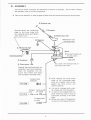
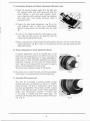
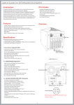
@ How to put microscope fixing blocks (provided with an optional wooden storage case)
The blocks should be put at the bottom of the
wooden storage case in the following order:
1. Insert the screw with the flat washer into
one of lhe two holes (8 mm4>1 as shown
in the drawing.
2. Turn the screw to gel into the block and
tighten it with the spanner provided or
a screwdriver.
3. Put the other block in the above order.
Wooden
storage case
Microscope
fixing block
<3
--jl-Bmm¢
I------
Flat washer
"".w
.____---=.=c.
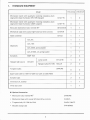
I.
STANDARD EQUIPMENT
CHA-213-W
Model
CHB-213-W
Microscope stand with quadruple revolving nosepiece, plain
CHA-F-W
1
0
stage and in-base illuminator (20W tungsten)
CHB-F-W
0
1
Binocular observation tube, inclined 45°
BH-B 145-W
1
1
Mechanical stage with coaxial right-hand low drive controls
CH-MVR
1
1
Abbe condenser
CH-CD
1
1
Ach_ 4X
1
1
Ach_ lOX
1
1
Ach. S40X. spring-loaded
1
1
Ach. SlOOX, oil. spring-loaded
1
1
Eyepieces
BiWF lOX
2
2
Halogen light source
CH-LSH
stage and in-base illuminator (6V lOW halogen)
Microscope stand with quadruple revolving nosepiece, plain
Objectives
Lamp socket
CH-LSHB
1
0
Halogen bulbs 6V lOW
HALCH
2
0
0
3
Spare fuses O.5A for lOO-110-120V (or O.3A for 220-240V)
2
2
Eyepiece caps
2
2
I mmersion oil, bottled
1
1
Vinyl dust cover
1
1
20WCHB
Tungsten bulbs
• Optional Accessories:
Monocular tube. inclined 45°
CH-M045
Mechanical stage with coaxial left-hand drive controls
CH-MVL
Tungsten bulb. 6V lOW for CHA
CH-6V lOW-TP
Wooden storage case
CHA-BIWSC
2
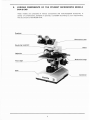
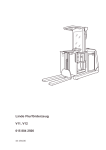
II.
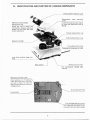
VARIOUS COMPONENTS OF THE STUDENT MICROSCOPES MODELS
CHA&CHB
These models are composed of various components and interchangeable accessories. A
variety of combinations, standard or optional, is available according to your requirements.
This is a picture of the Model CHA.
Eyepiece
Observation tube
Revolving nosepiece
Stand
Objective
Mechanical stage
Plain stage
Base
Condenser
~
a
3
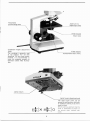
III.
ASSEMBLY
The picture below illustrates the sequential procedure of assembly. The numbers indicate
the assembly order of various components.
*
Take care at assembly to keep all glass surfaces clean and avoid scratching the lens surfaces.
® Eyepiece cap
~'" """>
Securely attach the mechanical
II\.
(J) Eyepiece
stage to the plain stage with
the clamping screws and tighten
them with a coin.
""~Observation
~
!
® Objective
11
tube
Observation tube
clamping screw
\
@ Mechanical stage
Stand
1
Clamping screws
---------~g~~g~O~L-®~9~connect
the plug to
~
th~outlet.
~
®
Condenser
®
Filter mount
A
t
Line cord
~~~
~
Pull down the locking knob of
the lamp house cover.
Aligning the positioning dots on
condenser mount and condenser,
insert the condenser into the
mount from below and clamp
with condenser clamping screw.
CD
Tungsten bulb
20WCHB
I For CHB I
After opening the lamp house
cover at the microscope base,
press the tungsten bulb socket
®::J
against
the lamp mount, and
rotate clockwise.
*
Halogen
bulb
I ForCHA I
Lamp socket
CH-LSHB
*
0-- Q
In case of the tungsten bulb, its
silver reflecting surface must be
positioned pointing to the base
*
Tungsten bulb
6V10W
I For CHA I
For use of a halogen bulb, insert
its contact pins into the socket.
Q:::J
4
plate.
Before use, wipe off fingerprints
or stains on the resPective bulbs.
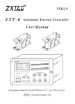
IV. IDENTIFICATION AND FUNCTION OF VARIOUS COMPONENTS
Interpupillary distance scale
Observation
tube
clamping
screw
Mechanical tube length
adjustment ring
Loosen the clamping screw slightly
to rotate the observation tube as
desired.
Rotate the ring to match your
interpupillary distance setting obtained from the scale. and make
diopter adjustment.
Tension adjustment ring
Coarse adjustment knob
Specimen holder
Fine adjustment knob
Graduated in increments of 2.5J.L•
....
....<O'!'!..............
Low drive coaxial stage
trois
con~
Sliding control lever
Main switch
For continuously variable light
intensitY.
Rheostat trimmer screw
After switching on, if necessary.
rotate this screw with a coin until
the bulb is dimly lit, with the
sliding control switch at minimum
voltage position.
Grounding terminal
Fuse holder
Line voltage selector switch
(For CHA) Set the switch to con-
form with the local mains voltage.
5
Automatic
pre-focusing lever
Aperture iris
diaphragm lever
Filter mount
Slip-in type.
~\~._._~I_~_-,---:::-F~il~te~r-:.mc:07u~n~t
Condenser height adjustment
knob
..........
The condenser is generally used
at top position. For use with
objectives lOX and lower power,
however, it is recommended to
lower the condenser properly to
eliminate uneven field illumination.
Accepts 45mm diam. filters.
Lamp mount
Lamp house clamping knob
The lamp house cover can be
opened by pulling down the knob;
or closed by pushing it up until it
snaps in place.
§iJx~o
6
Before pushing, ascertain that the
knob is positioned as shown in
the picture right, marked with
circle.
V.
OPERATION
•
Summary of Putting the Microscope in Operation
1. Match the line voltage selector switch to local mains voltage (for CHAI. (See
page 5,)
2. Switch on the light source.
3. Adjust the trimmer screw. (See page 7.1
4. Place a specimen slide on the stage. (See page 7.)
5. Loosen the automatic pre-focusing lever.
6. Coarse focus with a low power objective.
7. Make interpupillary and diopter adjustments. ISee page 8.)
8. Swing in the desired objective.
9. Adjust light intensity.
10. Fine focus.
11. Lock the automatic pre-focusing lever. (See page 8.1
12. Adjust the aperture iris diaphragm. ISee page 9.1
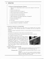
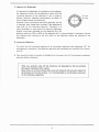
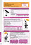
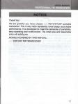
A. Adjustment of Minimum Line Voltage (CHA)
The minimum voltage required for the ligh t source can be adjusted with the rheostat
trimmer screw at the microscope base plate in accordance with the line voltage and
frequency.
The built·in rheostat incorporates a thyristor in its semi-conductor circuit for the following
advantages:
(a) Extremely fine adjustment of light intensity can be easily achieved.
(bl Flickering of the bulb filament is eliminated and the light intensity is stabilized.
Icl Increased life expectancy of the bulb.
For adjustment of the minimum line voltage, ascertain
that the voltage selector switch is set to conform with
the local mains voltage, and the sliding control lever CV
is positioned closest to you (low voltage). and then
activate the main switch CD. If the bulb is dimly lit,
the secondary VOltage is correct. If it is not lit at all,
rotate the rheostat trimmer screw @ gradually with a
coin, until the bulb is dimly lit; then push the sliding
control lever forward in order to obtain optimum light
intensity. (Fig. 1)
Fig. 1
8. Placing a Specimen Slide on the Stage
NOTE:
1) Cover glass:
Olympus objectives with an engraving "0.17" are corrected for
use with cover glasses of 0.17mm thickness (No. 1%).
2) Specimen slide:
It is recommended to use specimen slides of O.8mm to 1.5mm
thickness.
However, for use with the immersion darkfield condenser
BH-DCW (optionally availablel. a specimen slide between
O.8mm to 1.2m m th ickness is preferable.
7
C. Interpupillary Distance and Diopter Adjustments (Binocular tube)
1) Hold the knurled dovetail slides Q) of the right and
left eyepiece tubes with both hands and push the
tubes together, or pull them apart laterally, whichever is required, while looking through the eyepieces
with both eyes, until perfect binocular vision is
obtained (Fig. 21.
21 Rotate the tube length adjustment ring ® on the
right eyepiece tube to match your interpupillary
distance setting which you obtained from the scale
(
@.
Fig.2
(
3) Look at the image through the right eyepiece with
your right eye and focus on the specimen with the
coarse and fine adjustment knobs.
4) Next, looking at the image through the left eyepiece with your left eye rotate the tube
length adjustment ring @ to focus on the specimen without using the coarse and fine
adjustment knobs.
D. Tension Adjustment of Coarse Adjustment Knobs
A tension adjustment ring CD is provided next to the
right hand coarse adjustment knob. With this device the
tension of the coarse adjustment is freely adjustable for
either heavy or light movement depending on operator
preference. However, do not loosen the tension adjustment ring too much, because this may cause thE~ stage to
drop or the fine adjustment knobs to slip.
The arrow mark indicates increase of the tension.
*
Be careful not to rotate the right and left coarse adjustment knobs in the opposite directions simultaneously.
Fig. 3
E. Automatic Pre·focusing Lever
,
This lever CD is provided to prevent possible contact
between specimen and objective as well as to simplify
coarse focusing. The lever is locked after coarse focus
has been accomplished. This prevents further upward
travel of the stage by means of the coarse adjustment
knobs, and automatically provides a limiting stop
if the stage is lowered and then raised again. The
automatic pre-focusing lever does not restrict fine focusing. (Fig. 4)
8
Fig.4
F. Aperture Iris Diaphragm
An aperture iris diaphragm is provided on the condenser,
the opening of which can be adjusted to match with the
numerical aperture of the objective in use, in order to
achieve optimum objective performance, as depth of
focus, image contrast and resolution.
However, since microscopic specimens generally are low
in contrast, their image lacks contrast jf the objective is
used with its full numerical aperture. Therefore, it is
often preferable to stop down the aperture diaphragm
70-80%
slightly more than indicated by the objective N.A. An
aperture setting at 70% to 80% of the objective N.A. is recommended. If necessary, remove
the eyepiece and, looking at the exit pupil of the objective, adjust the opening of the
diaphragm.
G. Immersion Objectives
To utilize the full numerical aperture of an immersion objective (with engraving "HI" for
homogeneous immersion). the objective, specimen and condenser are immersed in an immersion oil.
*
Care should be taken to prevent oil bubbles from forming in the oil film between condenser,
specimen sl ide or objective.
After use, carefully wipe off the immersion oil deposited on the lens surfaces
with gauze moistened with xylene.
Never leave oil on lens surfaces after use as oil remnants will seriously impair the
performance of the lens systems. It is recommended to use Olympus immersion
oil for immersion objectives.
9
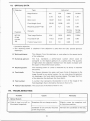
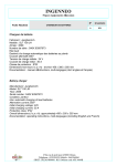
VI. OPTICAL DATA
Type
Objective
.,
Eyepiece
WFlOX
(Field
number
18)
Achromat
Magnification
4X
lOX
S40X
Sl00X'
NA
0.10
0.25
0.65
1.30
W.D.(mm)
19.87
5.40
0.39
0.11
Focal length (mml
29.20
15.98
4.31
1.81
Resolving power**{J-L)
3.4
1.3
0.52
0.26
Springloaded
Springloaded
Remarks
Total magnification
40X
100X
400X
1000X
Focal depth (Il)
172.5
27.60
3.03
0.66
Field of view (mm)
4.5
1.8
0.45
0.18
.. Immersion objective.
*·The resolving power is obtained if the objective is used with the fully opened aperture
diaphragm.
•
Working distance:
The distance from the specimen or cover glass to the nearest point
of the objective.
•
Numerical aperture:
The N.A. represents a performance number which could be
compared to the relativ(~ aperture of a camera lens. The quantity
of light which the objective receives from the object- increases with
the square of the performance number.
•
Resolving power:
The resolving power of a lens is measured by its ability to separate
two points.
•
Focal depth:
The distance between the upper and lower limits of sharpness in the
image formed by an optical system. As you stop down the aperture
iris diaphragm, the focal depth becomes deeper. The larger the N.A.
of the objective the shallower the focal depth.
•
Field number:
A number that represents the diameter in mm of the image of the
field diaphragm that is formed by the lens in front of it.
•
Field-of-viewdiameter: The actual size of the field of view in mm.
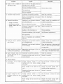
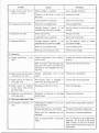
VII. TROUBLESHOOTING
Troubles
Causes
Remedies
1. Optical System
a) Field of view is cut off, or
illuminated irregularly.
Nosepiece did not change properly.
Slightly rotate the nosepiece until
it clicks into position.
Condenser is not correctly mounted
on the ring mount.
Re-insert the condenser all the way.
10
Troubles
bl Dust or dirt is visible in
the field of view.
Remedies
Causes
Dust or dirt on the glass surface at
the light exit on the base.
Dust on condenser top lens.
Remove dust or dirt.
Dirty specimen.
Dust on eyepiece.
cl Excessive image contrast.
dl Resolution problems:
·
··
Image is not sharp.
Insufficient contrast.
Image details lack definition.
Condenser is lowered excessively.
Raise the condenser.
Aperture iris diaphragm is stopped
down excessively.
Open the diaphragm.
Objective is not correctly position-
Slightly rotate the nosepiece until
ed in the light path.
it clicks into position.
Dirt on objective front lens.
Clean the objective.
Immersion objective is used without immersion oil.
Apply immersion oil.
Bubbles in the immersion oil.
Remove bubbles.
Olympus immersion oil is not used.
Use Olympus immersion oil.
Dirty specimen.
Dust on eyepieces and condenser
Clean.
top lens.
e) Field of view is partially
out of focus.
f) When objectives are chang~
ed they are not parfocal.
g) Light intensity does not
increase although the voltage is raised.
Objective is not correctly position-
Slightly rotate the nosepiece until
ed in the Iight path.
it clicks into position.
Specimen is not correctly positioned on the stage.
Place the specimen on the stage and
secure it with the specimen holder
or stage clips.
Mechanical tube length is not cor-
Adjust with the tube length adjust-
rectly adjusted.
ment rings on the observation tube.
Condenser is lowered excessively.
Raise the condenser.
Rheostat trimmer screw is not cor-
Adjust it correctly.
rectlyadjusted.
2. Electric System
a) Illuminator is too bright
(or too dark).
Voltage selector switch is not
matched with the mains voltage
(for CHA).
Set the switch to match the mains
voltage.
Mains voltage is too high (or too
low).
Adjust the mains voltage with a
variable voltage transformer.
Rheostat trimmer screw is not cor-
Adjust it correctly.
rectly adjusted.
bl Output voltage for the 11luminator cannot be regulated.
Voltage
selector switch is not
matched with the mains voltage
Set the switch to match the mains
voltage.
(for CHAI.
Mains voltage is too low (or too
high).
Adjust the mains voltage with a
variable voltage transformer.
Troubles
c) Light fl ickers and the in·
Causes
Remedies
Mains voltage is unstable.
Use a voltage stabilizer.
Filament of the bulb is likely to
Replace the bulb.
tensity is unstable.
burn out.
dl Fuse burns out too often.
e) Bulb does not light.
f) Reduced bulb life.
Loose electrical connection.
Secure the connection.
Fuse is not a standard fuse.
Use a standard fuse.
Voltage selector switch is not
matched with the mains voltage.
Set the switch to match the mains
Bulb is burned out.
Replace the bulb.
Loose electrical connection.
Secure the connection.
Voltage selector switch is not
matched with the mains \loltage.
Set the selector switch to match
Bulb is not a standard one.
Use a standard bulb.
Bulb was over vol ted too long.
Reduce bulb voltage.
Tension adjustment ring is tightened too much.
slightly.
voltage.
the mains voltage.
3. Focusing
a) Coarse adjustment is too
tight.
User is trying to raise the stage, passing over the upper focusing limit
imposed by the engaged pre-focusing lever.
b) Stage drops and the specimen goes out of focus.
c) Stage cannot be raised to
the upper limit.
dl Stage cannot be lowered
to the lower limit of the
Tension
loose.
adjustment
ring
is too
Pre-focusing lever is engaged
lower than focusing position.
in
Loosen the tension adjustment ring
Unlock the pre-focusing lever.
Tighten the ring slightly.
Unlock the pre·focusing lever.
Substage is lowered to much.
Raise the substage.
Specimen is mounted on the stage
upside down.
Reverse the specimen.
I nterpupillary distance is not cor-
Correct the interpupillary distance.
working range.
el Objective front lens touches the specimen.
4. Binocular Observation Tube
al Incomplete binocular vision.
rectlyadjusted.
Diopter adjustment is incomplete.
Complete the diopter adjustment.
Right and left eyepieces are not
Use a pair of matched eyepieces.
matched.
User is unaccustomed to binocular
vision.
Prior to looking at the image of the
specimen, try to look at the entire
field of view, or look at a far away
object before resuming microscopic
observation.