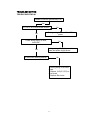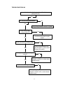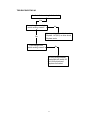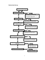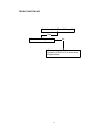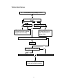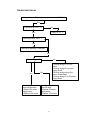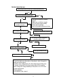
1
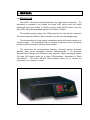
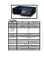
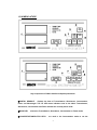
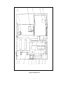
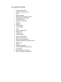
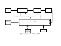
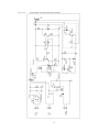
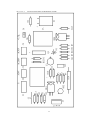
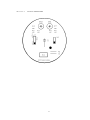
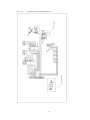
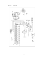
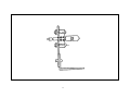
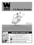
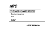
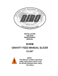
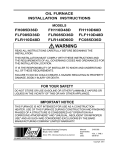
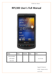
UNICO 2100 SERIES
SPECTROPHOTOMETER
Model 2100 Spectrophotometer
Model UV 2100 Spectrophotometer
SERVICE MANUAL
UNITED PRODUCTS & INSTRUMENTS INC.
●
MANUFACTURER OF QUALITY OPTICAL SYSTEMS
1-732-274-1155 (Phone)
www.unico1.com
1-732-274-1151 (Fax)
[email protected]
1. GENEARL
1.1 INTRODUCTION
The UNICO 2100 series spectrophotometers are single beam instruments. The
instruments is available in two models, the model 2100, which covers the Visible
wavelength region from 325nm to 1000nm and the model UV2100 which covers the
Ultra Violet and Visible wavelength regions from 200nm to 1000nm.
The analytical grating system has 1200grooves/mm for high spectral dispersion.
The nominal spectral slitwidth of 5nm is constant over the entire wavelength range.
The instruments have a large sample compartment which will accept cuvettes up to
100mm in length. The instruments have, as standard configuration a four cell manual
positioner which will accept 4 standard 10mm cuvettes.
The instruments are microprocessed featuring: Automatic zeroing, Automatic
blanking, Motor driven wavelength selection, Microprocessed T- A conversion,
Microprocessed Halogen and Deuterium lamp selection, Digital wavelength display.
The large LED display reads out in either %Transmittance, Absorbance or Direct
Concentration. The built-in RS232C serial interface allows you to connect the
instrument to you computer or printer.
UNICO 2100 Spectrophotometer
2
UNICO UV-2100 Spectrophotometer
1.2 SPECIFICATIONS:
Table 1
MODE
2100
UV-2100
Spectral Slitwidth
5nm
Optical System
Single Beam, Grating System 1200 lines/mm
Wavelength Range
325-1000nm(VIS)
200-1000nm(UV/VIS)
±2nm
Wavelength
Accuracy
Repeatability
Readability
±1nm
±1nm
±1nm
±0.002A/hr@500nm
Stability
Stray Light
≤ 0.3%T at 340 and 400nm
≤ 0.3%T at 220 and 340nm
Photometric Range
Accuracy
0-125%T, -0.1-2.5A, 0-1999C(0-1999F)
±[email protected]
Standard Cell Holder
4-position
Light Source
Data Output
Dimensions
Weight
Power Requirement
Tungsten Halogen Lamp
Tungsten Halogen/
Deuterium Lamp
Two-line, 9-LED, display Trans., Abs., Conc., and wavelength
RS232C, Analog Output
470mm(18.5”) W×400mm(15.7”) D×140mm(5.5”) H
10Kg
12Kg
115/230 volt. ±10%, 60/50Hz.Adjustable
3
1.3 NOMENCLATURE
Key Components of UNICO 2100 Series Spectrophotometer
①DIGITAL READOUT
displays the data of Transmittance, Absorbance, Concentration,
Factor and Wavelength. The red LED status indicators next to the labels Transmittance,
Absorbance, Concentration and Factor indicate the currently active mode.
②MODE KEY
selects the Transmittance, Absorbance, Concentration or Factor mode.
③ CONCENTRATION/FACTOR KEYS
are used in the Concentration mode to set the
4
concentration and/or Factor value of a known standard on the digital display.
④PRINT BUTTON
to send displayed data to a printer or computer connected to the
RS232C serial port.
⑤100%T/0A KEY
is used to set digital display to 100%T or 0Abs. It must be reset whenever
the analytical wavelength has been changed.
NOTE: When operating at a fixed wavelength for an extended period of time, check the 0%T
and 100%T readout and readjust if necessary.
⑥WAVELENGTH SELECTOR BUTTON
used to select the desired analytical wavelength of
the instrument. The wavelength readout digital display is graduated in 1nm increments.
⑦ RS-232C PORT
located on the back of the instrument. The pin functions for the
connector are listed below:
1-Chassis ground
2-UNICO transmits data
3-UNICO receive data
7-Signal ground
⑧THE RS-232C
parameters are:
Baud Rate -4800
Date Bit -8
Stop Bit -1
Parity - None
⑨ANALOG OUTPUT
Connector is a double-banana socket located on the back of the
instrument
Operating Components of Back Side of UNICO 2100 (VIS Model Only)
5
6
1.4 LAYOUT OF 2100 AND UV2100
1.4.1 LAYOUT OF 2100
1.
Lamp Compartment
2.
Tungsten Halogen Lamp
3.
Mirror
4.
Monochromator
5.
Wavelength Position Switch
6.
Motor(Wavelength Drive)
7.
Condenser Lens
8.
Sample Compartment
9.
Detector
10. Amplifier
11. Power Supply Section
12. Power Switch
13. Fuse
14. Power Supply Board
15. Electric Fan
16. Transformer
17. Interface Board
18. Second Order Filters
19. Motor(Second order filter)
7
Layout of UNICO 2100
8
1.4.2 LAYOUT OF UV2100
1.
2.
3.
4.
5.
6.
7.
8.
9.
10.
11.
12.
13.
14.
15.
16.
17.
18.
19.
20.
21.
22.
23.
24.
25.
26.
27.
28.
Lamp Compartment
Tungsten Halogen Lamp
Mirror
Monochromator
Wavelength Positioning Switch
Motor (Wavelength Drive)
Condenser Lens
Sample Compartment
Detector
Amplifier
Power Supply
Power Switch
Fuse
Power Supply Board
Electric Fan
Transformer
Interface Board
Second Order Filters
Deuterium Lamp (D2)
Motor (Lamp changeover)
Halogen-Deuterium changeover lever
Plane mirror
Switch
Light blocking shelf
Power Supply Board (D2 lamp)
Transformer
Motor (Second order filters)
Power Transistor and heat sink
9
Layout of UV 2100
10
Layout of UV 2100
1.5 THE SYSTEM
All of the electronic components except the power transistor are installed on four circuit
boards.
1.
Main power supply board
2.
CPU Board
3.
Deuterium power supply and current regulator board
4.
Amplifier Board
\
1.5.1
The flow block diagrams are shown in Figure ________ and Figure ________.
When the instrument is turned on, the instrument will automatically go through a shelf
test and self calibrating procedure as follows:
A.
Locate instrument baseline, wavelength baseline, filter positioning baseline.
B.
Memorize dark current: the instrument is shut down and automatically after
the instrument baseline is located and the dark current will be measured.
C.
The instrument is again automatically turned on, the wavelength of 546nm will
pass through the sample compartment (air is used as a reference) and
impinge on the detector. The photodetector will generate photo current.
The photo current signal is then amplified and converted from an analog signal
to a digital signal. The digital signal is sent to the CPU. The CPU compares
the signal received to the memorized dark current. It then determines the
proper lamp voltage and system gains so %Transmittance zeroing and 100%T
Blanking are achieved. The instrument will display 100%T.
Whenever you change or select another wavelength to measure you
need to blank first with a reference solution, otherwise the instrument will not
accept any commands.
11
Power
Sample
Detector
Compartment
Amplifier
Monochromator
Source
Filter selection control and baseline control
GOTO Wavelength control and baseline control
Keyboard
V
F
C
CPU
Display
T/A/C/F
Wavelength
Fig.1.5.1.1 System Block Diagram(2100)
RS232
Power
Sample
Detector
Compartment
Amplifier
Monochromator
Source
Filter selection control and baseline control
GOTO Wavelength control
Halogen-D 2 lamp change control
Keyboard
V
F
C
CPU
Display
T/A/C/F
RS232
Wavelength
Fig. 1.5.1.2
System Block Diagram(UV2100)
13
1.5.2 OPTICAL SYSTEM
The optical system schematic diagram for the UNICO 2100 and UV2100 instruments
are shown in Figure ________ and Figure ________.
The neutral light coming from the Halogen lamp or the Deuterium lamp is focused by the
concave mirror, passed through the entrance slit of the monochrometer, reflected by the
collomating mirror 2 to the analytical grating. The light is spectrally dispersed by the
grating and reflected by the collomating mirror 2 to the exit slit, through a condenser
lens continue on through the sample compartment and finally to the photodetector.
1.5.2
Optical System Schematic Diagram (UV2100)
Concave mirror 1
Halogen
lamp
Mirror
D2 lamp
Entrance slit
Exit slit
Detector
Concave mirror 2
Condenser
lens
Sample
compartment
Condenser
lens
Filter
Mirror
Grating
1.5.2
Optical System Schematic Diagram (2100)
18
Concave mirror 1
Entrance slit
Exit slit
Detector
Condenser
lens
Sample
compartment
Condenser
lens
Halogen lamp
Mirror
Filter
Concave mirror 2
Grating
19
1.5.3Electronic system
Fig.1.5.3.1
Fig. 1.5.3.1.1
Fig. 1.5.3.2
Fig. 1.5.3.2.1
Fig. 1.5.3.3
Fig. 1.5.3.3.1
Fig. 1.5.3.4
Fig. 1.5.3.4.1
Fig. 1.5.3.5
Fig. 1.5.3.5.1
Power Supply and Control Circuit for Halogen Lamp
Layout of Power Supply and Control Board for Halogen Lamp Board
Power Supply Circuit for D2 Lamp (UV-2100)
Layout of Power Supply for D2 Board (UV-2100)
Amplifier Circuit
Layout of Amplifier Board
Motor Drive and Limit Switch Diagram
Layout of Motor Drive and Limit Switch Board
CPU Circuit
Layout of CPU Board
Fig.1.5.3.1
Power Supply and Control Circuit for Halogen Lamp
22
Fig. 1.5.3.1.1
Layout of Power Supply and Control Board for Halogen Lamp Board
23
Fig. 1.5.3.2
Power Supply Circuit for D2 Lamp (UV-2100)
24
Fig. 1.5.3.2.1
Layout of Power Supply for D2 Board (UV-2100)
25
Fig. 1.5.3.3
Amplifier Circuit
26
Fig. 1.5.3.3.1
Layout of Amplifier Board
27
Fig. 1.5.3.4
Motor Drive and Limit Switch Diagram
28
Fig. 1.5.3.4.1
Layout of Motor Drive and Limit Switch Board
29
Fig. 1.5.3.5
CPU Circuit
30
Fig. 1.5.3.5.1
Layout of CPU Board
31
2.MAINTENANCE
*
Working Environment
The optimum environment for the instrument is as follows:
Temperature
Humidity
5°to 35℃
<85%
Install the instrument in a clean non-vibrational area. Avoid direct strong light and air
flow. The instrument will give better performance if the power supply stability is greater
than ±10% and the line frequency is greater than ±1Hz. Always allow the instrument
to warm up for 20 minutes prior to taking any readings.
*
Replacing Tungsten-Halogen lamp and Adjustment
Replacing Lamp: Refer to the “Operators Manual”
Adjustment: Turn the instrument on and make sure the wavelength is in the
visible range (for the UV2100). The light image (rectangular shape) should be focused
on the entrance slit of the monochrometer as shown in Figure ________. If not, loosen
the locking screws and move the lamp in the desired direction until the image is
centered on the entrance slit. Then tighten the locking screws firmly.
*
Replacing the Deuterium lamp.
Replacing the D2 Lamp--refer to the “Operators Manual”
Adjustment--adjustment is not necessary--the lamp is prealigned.
The light spot of the Deuterium lamp should be focused on the entrance slit of the
monochrometer as shown in Figure ________. If the spot is not on the slit, loosen and
adjust the screws of the D2 lamp bracket to bring the spot to the center of the entrance
slit. Tighten the screws firmly.
UNICO 2100 Series
Spectrophotometer
MAINTENANCE
Follow these instructions carefully to avoid injury to yourself or damage to the UNICO
2100 series spectrophotometer!
IT IS RECOMMENDED YOU CONTACT AN
AUTHORIZED SERVICE REPRESENTATIVE TO PERFORM ANY MAINTENANCE
OR REPAIRS ON THE UNICO SPECTROPHOTOMETERS.
TO REPLACE HALOGEN LAMP
TURN OFF AND UNPLUG THE INSTRUMENT.
Remove the four screws on the sides of the spectrophotometer.
Remove the cuvette holder rod by unscrewing the rod counterclockwise.
Very carefully remove the cover of the instrument and place in front of the
instrument, taking care not to unplug any of the connections inside the instrument.
5. Loosen but do not remove the two top screws on the lamp base.
6. Remove the lamp from the ceramic base.
7. Carefully replace the new lamp.
8. Retighten the two screws on the lamp base.
CAUTION: Do not handle Halogen lamp with bare fingers. Use a piece of tissue or
cloth when handling the lamp. The oil from your fingers can cause the lamp to
burn out prematuratcly!!!
9. Carefully replace instrument cover and replace screws.
1.
2.
3.
4.
TO REPLACE DEUTERIUM LAMP
TURN OFF AND UNPLUG THE INSTRUMENT.
Remove the four screws on the sides of the spectrophotometer.
Remove the cuvette holder rod by unscrewing the rod counterclockwise.
Very carefully remove the cover of the instrument and place in front of the
instrument, taking care not to unplug any of the connections inside the instrument.
5. Remove the metal plate covering the Deuterium Lamp by removing the two screws
from the rear of the plate.
6. Remove the lamp from the instrument and replace with a new lamp.
7. Reverse the order from lines 5 through line 2.
CAUTION: THE LAMP MAY BE HOT—TAKE PRECAUTIONS TO PREVENT BURNS
FROM THE LAMP.
1.
2.
3.
4.
34
The Correct Position of Light Spot on Entrance Slit
Halogen
Light Spot
Entrance Slit
Halogen Lamp
D2
Light Spot
Entrance Slit
Deuterium Lamp
36
37
1
2
3
4
5
6
7
Filter
Wavelength
BLACK
VIOLET
NAUTRAL
ORANG
DEEP RED
Vacant
Vacant
335~370nm
380~450nm
450~550nm
550~750nm
750~1000nm
MAINTENANCE
*
WAVELENGTH CALIBRATION
*
Wavelength calibration check
Refer to the “Operator’s Manual”
*
Wavelength Calibration:
The Wavelength accuracy is ±2nm.
If the wavelength is off, it
can be adjusted. A JMP calibration terminal can be found on the bottom
right corner of the CPU board. There are 8 pins in four rows (2 pins in
each row). The following definitions are made in the system.
For Row B, C, D
If 2 pins in a row are connected, the result is defined as “1”.
If 2 pins in a row are not connected the result is defined as “0”.
For Row A (Very right row)
If the 2 pins are connected the result is defined as “-“.
If the 2 pins are not connected the result is defined as “+”.
D
C
0
0
0
0
1
1
1
1
0
0
0
0
1
1
1
1
0
0
1
1
0
0
1
1
0
0
1
1
0
0
1
1
B
A
0
1
0
1
0
Results
-
1
0
1
0
1
0
1
0
1
0
1
+
+
+
+
+
+
+
+
0nm
-1nm
-2nm
-3nm
-4nm
-5nm
-6nm
-7nm
0nm
+1nm
+2nm
+3nm
+4nm
+5nm
+6nm
+7nm
CPU Board
D C
B A
UNICO 2100 Series
Spectrophotometer
WAVELENGTH CALIBRATION CHECK
As usual the UNICO 2100 series spectrophotometer retains its wavelength calibration
indefinitely. However if the instrument receives a sever shock or is abused, use the
following methods to check wavelength calibration.
In the Didymium filter method, the filter has two special absorbance peaks at 529nm
and 808nm. When the instrument is calibrated properly you will find minimum
Transmittance (maximum absorbance) at the range of 529nm (or 808nm) ±2nm. Note
that the specific transmittance values are not important as you are only looking for the
wavelength where minimum transmittance (maximum absorbance) occurs.
1.
2.
3.
4.
5.
6.
7.
8.
9.
Turn instrument on and allow it to warm up for 15 minutes.
Select the %Transmittance operating mode.
Set the wavelength to 519nm.
Insert the cuvette filled with distilled water in position 1 in the cuvette holder.
Insert the didymium filter in position 2 in the cuvette holder.
Place the cuvette holder into the sample compartment, put the distilled water
cuvette into the light path and set 100%T.
Place the didymium filter in the light path and record the %T reading on the digital
display.
Repeat steps 3 through 7 to measure separately the wavelength of the points
between 519nm and 539nm.
Looking for the minimum Transmittance along this record, the minimum
%Transmittance should be obtained between 526nm and 532nm. The wavelength
accuracy of the 2100 spectrophotometer is ±2nm.
Figure 5:
523
nm
Check The Wavelength Calibration with Didymium Filter
40
TROUBLESHOOTING
TROUBLESHOOTING #1
Unable to find filter limit switch(2100)
Yes
Is +12V of J6 on drive board normal?
No
Yes
Solving wiring between J6 and PC
power
Check wiring(10pin) on drive
board,OK?
No
Yes
Solving wiring (10pin)between drive
board and power supply board
Is filter motor working normal?
No
1.Solving wiring J4 on drive
board
2.Replace 1413(IC1,IC2) on
drive board
3.Replace filter motor
41
TROUBLESHOOTING #2
Unable to find light limit switch or filter limit
switch(UV2100)
Yes
Is +12V of J6 on drive board?
No
Yes
Solving wiring between J6 and PC power
Check wiring(10pin)
on drive board,OK?
No
Solving wiring(10pin)between
drive board and power supply
board
Yes
Is light limit switch working normal?
No
1.Solving wiring between limit
switch K1 and J7 on drive board
2.Replace limit switch
Yes
Is light switch motor working
normal?
Yes
No
1.Solving wiring J5 on drive board
2.Replace 1413(IC1) on drive board
3.replace motor
Is filter motor working normal?
No
1.Solving wiring J4 on drive board
2.Replace 1413(IC1,IC2) on drive board
3.replace motor
42
TROUBLESHOOTING #3
Unable to find wavelength limit switch
Yes
Is wavelength motor limit
switch working normal?
Yes
No
1.Solving wiring J3 on drive board
2.Replace 1413(IC2) on drive board
3.Replace motor
Is wavelength limit
switch working normal?
No
1.Solving wiring between
wavelength limit switch K2
and J8 on drive board
2.replace limit switch
43
TROUBLESHOOTING #4
Unable to find "0" order light
Yes
Is light from halogen lamp?
No
1.Replace halogen lamp(6V10W)
2.If lamp OK,Check the voltage regulator
circuit on power supply board
Yes
Is light out of the road?
No
Yes
Adjust the light to the right position.
Is photoelectricity-coupling
working normal?
No
1.Solving wiring J4 on drive board
2.replace photoelectricity-coupling
Yes
Is amplifier working normal?
Yes
No
1.Check amplifier circuit
2.solving wiring J4 on power supply
board
Check wiring(26pin) on drive board,OK?
Yes
No
Solving wiring between J1(26pin) on
drive board and J1 on CPU board
Check wiring of single on CPU
board,OK?
No
Solving wiring between J5
on CPU board and J3 on
power supply board
Yes
Is CPU board working normal?
No
Replace CPU board
44
TROUBLESHOOTING #5
Unable to adjust to "0" and "full range"
Yes
Is filter motor working normal?
No
1.Solving wiring J4 on drive board
2.Replace 1413(IC1,IC2) on drive board
3.Replace board
45
TROUBLESHOOTING #6
At "T" mode,blank(100%),,display <<100.0
Yes
Is wavelenght within visual
range?
Yes
No
Is D2 lamp on?
Is halogen lamp on?
No
No
Yes
1.Replace D 2 lamp
2.If lamp OK,circuit on power
supply board of D 2 lamp
1.Replace halogen lamp
2.If lamp OK,circuit on
power supply board of
halogen lamp
Anything in sample comparment blocking the light?
Yes
Remove it
No
Is the light out of the road?
No
Yes
Adjust it to the right position
Is filter at the right position?
No
Get rid of the matter of the filter
motor,and adjust the position
46
TROUBLESHOOTING #7
Turn on,display not stable
Yes
Warm up enough?
Warm up at least 20 minutes
Yes
Groung OK?
No
Solving ground of power
supply
Yes
Check power supply normal?
No
Improve power
supply(Max.+10%--10%)
Yes
PC power supply normal?
No
Replace PC power
Yes
Check voltage regulator for
halogen lamp normal?
No
Check voltage regulator
circuit repair or replace
Yes
No
No
Yes
Check photo-detector normal?
No
Replace photo-detector
Yes
Check amplifier normal?
No
Replace amplifier
Is wavelength within 200-399nm
range?
Yes
Check current regulator for
D2 lamp working normal?
No
Pepair or replace the
current regulator
Yes
Is D2 lamp working fine?
No
Replace D 2 lamp
47
TROUBLESHOOTING #8
LED display not complete
Yes
LED OK?
No
Yes
Replace LED
Replace CPU board
48
TROUBLESHOOTING #9
Halogen lamp or D2 lamp button does not work(UV2100)
Yes
Is mode set at "A"or "T"?
No
Select "A" or "T"
Yes
Blanking,display "BLA---"?
Yes
Waiting still blanking is complete
No
Check wiring OK?
Yes
Unable to open and
close halogen lamp
1.Replace D2 power
supply board
2.Replace CPU board
No
1.Solving wiring J1 on CPU
board
2.Solving wiring J8 on power
supply board
3.Solving wiring wiring J5on
power supply board
4.Solving wiring J5 on D2 power
supply board
Yes
Unable to open and
close D2 lamp
1.Replace D2 power
supply board
2.Replace CPU board
49
TROUBLESHOOTING #10
Measuring recelts incorrect(not stable,repeatability,etc)
Yes
Is sample preparation adjust right?
Yes
No
1.Use right procedures to prepare
samples
2.Make sure no bubble in sample
3.Test only after sample stability
4.Select right wavelength
5.get rid of possible interference factors
Is sample preparation
installed correctly?
Yes
No
Are cuvettes used matched?
Install the compartment correctly
No
Yes
Use matched cuvetter difference
should be within 0.5%T
Is wavelength accurate?
No
Yes
Calibrate wavelength
Are %T and 100%T correct?
Yes
No
Use right procedue to set
Is photometric accuracy maintained?
No
1.Check if the light arrive the surface of the detector after it through the
sample,can't arrive,adjust it
2.Amplifier output voltage(stactic):20--30mV.Adjust way:put black body
into sample comparment to blocking the light,adjust W1 on amplifier
board to change the voltage between pin3 and pin4 of J4 to 20--30mV
on power supply board
3.Replace detector
4.Use NBS930D filter check it
50