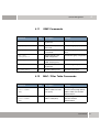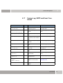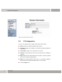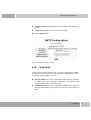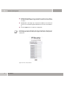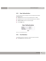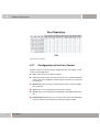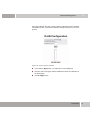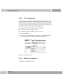
1
User Manual
funkwerk S128p FastEthernet PoE Switch
Copyright © November 20, 2007 Funkwerk Enterprise Communications GmbH
Version 1.1
Purpose
This document describes the installation and usage of the funkwerk S128p FastEthernet PoE
Switch.
Liability
While every effort has been made to ensure the accuracy of all information in this manual, Funkwerk
Enterprise Communications GmbH cannot assume liability to any part for any loss or damage caused
by errors or omissions or by statements of any kind in this document and is only liable within the scope
of its terms of sale and delivery.
The information in this manual is subject to change without notice. Additional information and modifications can be found under www.funkwerk-ec.com.
Trademarks
Company names, product names, and trademarks mentioned are usually the property of the respective companies and manufacturers.
Copyright
All rights are reserved. No part of this publication may be reproduced or transmitted in any form or by
any means – graphic, electronic, or mechanical – including photocopying, recording in any medium,
taping, or storage in information retrieval systems, without the prior written permission of Funkwerk Enterprise Communications GmbH. Adaptation and especially translation of the document is inadmissible
without the prior consent of Funkwerk Enterprise Communications GmbH.
Guidelines and Standards
Funkwerk products comply with the following guidelines and standards:
R&TTE Directive 1999/5/EC
CE marking for all EU countries and Switzerland
You can find detailed information in the Declarations of Conformity under www.funkwerk-ec.com.
How to Reach Funkwerk Enterprise Communications
GmbH
Funkwerk Enterprise Communications GmbH
Suedwestpark 94
D-90449 Nuremberg
Germany
Telephone: +49 180 300 9191 0
Fax: +49 180 300 9193 0
Internet: www.funkwerk-ec.com
CE Mark Warning
This is a class A product. If operated in a domestic environment, the device may cause interferences.
As a result, the user may have to take appropriate countermeasures.
1
Introduction . . . . . . . . . . . . . . . . . . . . . . . . . . . . . . . . . . . . . . . . . . . . 5
2
Description of the Hardware . . . . . . . . . . . . . . . . . . . . . . . . . . . . . . 13
2.1
Desktop Installation . . . . . . . . . . . . . . . . . . . . . . . . . . . . . . . . . . . . . . . . . 15
2.2
Attaching the Rubber Feet . . . . . . . . . . . . . . . . . . . . . . . . . . . . . . . . . . . . 15
2.3
Connection to the Power Supply . . . . . . . . . . . . . . . . . . . . . . . . . . . . . . . 16
3
Network Application . . . . . . . . . . . . . . . . . . . . . . . . . . . . . . . . . . . . 17
4
Console Management . . . . . . . . . . . . . . . . . . . . . . . . . . . . . . . . . . . 19
4.1
Log-on to the Console Interface . . . . . . . . . . . . . . . . . . . . . . . . . . . . . . . . 19
4.2
CLI Management . . . . . . . . . . . . . . . . . . . . . . . . . . . . . . . . . . . . . . . . . . . 21
4.3
Command Level . . . . . . . . . . . . . . . . . . . . . . . . . . . . . . . . . . . . . . . . . . . . 22
4.4
List of Commands . . . . . . . . . . . . . . . . . . . . . . . . . . . . . . . . . . . . . . . . . . 24
4.5
System Commands . . . . . . . . . . . . . . . . . . . . . . . . . . . . . . . . . . . . . . . . . 24
4.6
Port Commands . . . . . . . . . . . . . . . . . . . . . . . . . . . . . . . . . . . . . . . . . . . . 27
4.7
Trunk Commands . . . . . . . . . . . . . . . . . . . . . . . . . . . . . . . . . . . . . . . . . . . 30
4.8
VLAN Commands . . . . . . . . . . . . . . . . . . . . . . . . . . . . . . . . . . . . . . . . . . . 31
4.9
Spanning Tree Commands . . . . . . . . . . . . . . . . . . . . . . . . . . . . . . . . . . . 33
4.10
QoS Commands . . . . . . . . . . . . . . . . . . . . . . . . . . . . . . . . . . . . . . . . . . . . 36
4.11
IGMP Commands . . . . . . . . . . . . . . . . . . . . . . . . . . . . . . . . . . . . . . . . . . . 37
4.12
MAC / Filter Table Commands . . . . . . . . . . . . . . . . . . . . . . . . . . . . . . . . . 37
4.13
SNMP Commands . . . . . . . . . . . . . . . . . . . . . . . . . . . . . . . . . . . . . . . . . . 38
4.14
Port Mirroring Commands . . . . . . . . . . . . . . . . . . . . . . . . . . . . . . . . . . . . 41
4.15
802.1x Commands . . . . . . . . . . . . . . . . . . . . . . . . . . . . . . . . . . . . . . . . . . 42
4.16
TFTP Commands . . . . . . . . . . . . . . . . . . . . . . . . . . . . . . . . . . . . . . . . . . . 44
User Manual
1
5
2
4.17
System Log, SMTP and Event Commands . . . . . . . . . . . . . . . . . . . . . . . .45
4.18
SNTP Commands . . . . . . . . . . . . . . . . . . . . . . . . . . . . . . . . . . . . . . . . . . .47
4.19
X Ring Commands . . . . . . . . . . . . . . . . . . . . . . . . . . . . . . . . . . . . . . . . . . .49
Web-Based Management . . . . . . . . . . . . . . . . . . . . . . . . . . . . . . . . .51
5.1
Web-Based Management . . . . . . . . . . . . . . . . . . . . . . . . . . . . . . . . . . . . .51
5.2
Preparation for Web Management . . . . . . . . . . . . . . . . . . . . . . . . . . . . . . .51
5.3
System Log-on . . . . . . . . . . . . . . . . . . . . . . . . . . . . . . . . . . . . . . . . . . . . . .52
5.4
System Information . . . . . . . . . . . . . . . . . . . . . . . . . . . . . . . . . . . . . . . . . .53
5.5
IP Configuration . . . . . . . . . . . . . . . . . . . . . . . . . . . . . . . . . . . . . . . . . . . . .54
5.6
DHCP Configuration . . . . . . . . . . . . . . . . . . . . . . . . . . . . . . . . . . . . . . . . .55
5.6.1
Configuration of the DHCP Server . . . . . . . . . . . . . . . . . . . . . . . .56
5.6.2
Entries of the DHCP Client . . . . . . . . . . . . . . . . . . . . . . . . . . . . . .57
5.6.3
Port and IP Binding . . . . . . . . . . . . . . . . . . . . . . . . . . . . . . . . . . . .58
5.7
Update Firmware . . . . . . . . . . . . . . . . . . . . . . . . . . . . . . . . . . . . . . . . . . . .58
5.8
Restore of the Configuration . . . . . . . . . . . . . . . . . . . . . . . . . . . . . . . . . . .59
5.9
Backup Configuration . . . . . . . . . . . . . . . . . . . . . . . . . . . . . . . . . . . . . . . .60
5.10
Configuration of the System Log . . . . . . . . . . . . . . . . . . . . . . . . . . . . . . . .60
5.11
SMTP Configuration . . . . . . . . . . . . . . . . . . . . . . . . . . . . . . . . . . . . . . . . .62
5.12
Configuration of Events . . . . . . . . . . . . . . . . . . . . . . . . . . . . . . . . . . . . . . .63
5.13
SNTP Configuration . . . . . . . . . . . . . . . . . . . . . . . . . . . . . . . . . . . . . . . . . .65
5.14
IP Security . . . . . . . . . . . . . . . . . . . . . . . . . . . . . . . . . . . . . . . . . . . . . . . . .67
5.15
User Authentication . . . . . . . . . . . . . . . . . . . . . . . . . . . . . . . . . . . . . . . . . .69
5.16
Port Statistics . . . . . . . . . . . . . . . . . . . . . . . . . . . . . . . . . . . . . . . . . . . . . . .69
5.17
Configuration of the Port Control . . . . . . . . . . . . . . . . . . . . . . . . . . . . . . . .70
User Manual
5.18
Port Trunk . . . . . . . . . . . . . . . . . . . . . . . . . . . . . . . . . . . . . . . . . . . . . . . . . 71
5.18.1 Trunk Group Settings . . . . . . . . . . . . . . . . . . . . . . . . . . . . . . . . . 72
5.18.2 Information on Trunk Aggregation . . . . . . . . . . . . . . . . . . . . . . . . 73
5.18.3 Activity State . . . . . . . . . . . . . . . . . . . . . . . . . . . . . . . . . . . . . . . . 74
5.19
Port Mirroring . . . . . . . . . . . . . . . . . . . . . . . . . . . . . . . . . . . . . . . . . . . . . . 75
5.20
Bandwidth Limitation . . . . . . . . . . . . . . . . . . . . . . . . . . . . . . . . . . . . . . . . 76
5.21
VLAN Configuration . . . . . . . . . . . . . . . . . . . . . . . . . . . . . . . . . . . . . . . . . 78
5.21.1 Port-Based VLAN . . . . . . . . . . . . . . . . . . . . . . . . . . . . . . . . . . . . 78
5.21.2 802.1Q VLAN . . . . . . . . . . . . . . . . . . . . . . . . . . . . . . . . . . . . . . . 80
5.22
Rapid Spanning Tree . . . . . . . . . . . . . . . . . . . . . . . . . . . . . . . . . . . . . . . . 84
5.22.1 RSTP System Configuration . . . . . . . . . . . . . . . . . . . . . . . . . . . . 85
5.22.2 RSTP Configuration per Port . . . . . . . . . . . . . . . . . . . . . . . . . . . . 86
5.23
SNMP Configuration . . . . . . . . . . . . . . . . . . . . . . . . . . . . . . . . . . . . . . . . . 88
5.23.1 System Configuration . . . . . . . . . . . . . . . . . . . . . . . . . . . . . . . . . 89
5.23.2 Trap Configuration . . . . . . . . . . . . . . . . . . . . . . . . . . . . . . . . . . . 90
5.23.3 SNMPv3 Configuration . . . . . . . . . . . . . . . . . . . . . . . . . . . . . . . . 90
5.24
QoS Configuration . . . . . . . . . . . . . . . . . . . . . . . . . . . . . . . . . . . . . . . . . . 94
5.24.1 QoS Policy and Priorities . . . . . . . . . . . . . . . . . . . . . . . . . . . . . . . 94
5.24.2 Port-Based Priority . . . . . . . . . . . . . . . . . . . . . . . . . . . . . . . . . . . 96
5.24.3 CoS Configuration . . . . . . . . . . . . . . . . . . . . . . . . . . . . . . . . . . . . 96
5.24.4 ToS Configuration . . . . . . . . . . . . . . . . . . . . . . . . . . . . . . . . . . . . 96
5.25
IGMP Configuration . . . . . . . . . . . . . . . . . . . . . . . . . . . . . . . . . . . . . . . . . 97
5.25.1 IGMP Configuration . . . . . . . . . . . . . . . . . . . . . . . . . . . . . . . . . . . 97
5.25.2 X Ring . . . . . . . . . . . . . . . . . . . . . . . . . . . . . . . . . . . . . . . . . . . . . 98
5.26
Security Configuration . . . . . . . . . . . . . . . . . . . . . . . . . . . . . . . . . . . . . . 100
5.26.1 802.1x Configuration . . . . . . . . . . . . . . . . . . . . . . . . . . . . . . . . . 100
5.26.2 Port Security . . . . . . . . . . . . . . . . . . . . . . . . . . . . . . . . . . . . . . . 103
5.27
Power over Ethernet . . . . . . . . . . . . . . . . . . . . . . . . . . . . . . . . . . . . . . . . 107
User Manual
3
6
5.28
Default Settings . . . . . . . . . . . . . . . . . . . . . . . . . . . . . . . . . . . . . . . . . . . .108
5.29
Save Configuration . . . . . . . . . . . . . . . . . . . . . . . . . . . . . . . . . . . . . . . . .109
5.30
System Reboot . . . . . . . . . . . . . . . . . . . . . . . . . . . . . . . . . . . . . . . . . . . .110
Troubleshooting . . . . . . . . . . . . . . . . . . . . . . . . . . . . . . . . . . . . . . .111
6.1
Incorrect Connections . . . . . . . . . . . . . . . . . . . . . . . . . . . . . . . . . . . . . . .111
6.2
Error Diagnosis via LEDs . . . . . . . . . . . . . . . . . . . . . . . . . . . . . . . . . . . . .112
7
Specifications . . . . . . . . . . . . . . . . . . . . . . . . . . . . . . . . . . . . . . . . .113
8
Appendix . . . . . . . . . . . . . . . . . . . . . . . . . . . . . . . . . . . . . . . . . . . . .115
8.1
Pin Assignment at the Console Port . . . . . . . . . . . . . . . . . . . . . . . . . . . .115
8.2
Cables . . . . . . . . . . . . . . . . . . . . . . . . . . . . . . . . . . . . . . . . . . . . . . . . . . .116
8.3
100BASE-TX/10BASE-T Pin Assignment . . . . . . . . . . . . . . . . . . . . . . . .117
8.3.1
4
User Manual
RJ-45 Pin Assignment of PDs Which Do not Comply to Standard
802.3af, with Mid-Span POE HUB RJ-45 Pin Assignment . . . . .117
1
Introduction
1
Introduction
When using Power-over-Ethernet (PoE), the devices are powered via network
cabling with a voltage of 110/220 V AC. If Power-over-Ethernet is applied, only
one Cat. 5 Ethernet cable is required, which transports both the power and data
to each device. This offers more flexibility in the placement of the network devices and leads to considerable cost reduction in many cases.
In the case of PoE, two system components are used: the Power Sourcing
Equipment (PSE), which provides the power and sets up the connection to the
second component, the Powered Device (PD). The electric current flows over 2
of the 4 twisted pair wires of the Cat. 5 cable.
Power-over-Ethernet complies to the IEEE 802.3af Standard and is absolutely
compatible with state-of-the-art Ethernet switches and network devices. The
Power Sourcing Equipment (PSE) checks whether the network device is PoEcapable. This means that a current will only flow if it has been ensured that a
powered device has been connected at the other end of the cable. Moreover,
the PSE monitors the transmission channel. If the powered device does not use
up a minimum power, because it has been disconnected or switched off, the
PSE will switch off the power supply to this port. As an option, the standard permits the powered devices to signal the PSEs how much power they precisely
require.
The funkwerk S128p FastEthernet PoE Switch is a multi-port switch which
can be used to set up high-performance, switched workgroup networks. The
switch is a device which permits store-and-forward switching and offers low latencies for high-speed networks. The switch uses a scheme for store-and-forward switching. This enables the switch to perform auto-learning and to store
source addresses in a MAC address table by means of 8 K entries. The switch
has been designed for the operation in networks for workgroups, departments,
or backbones. The funkwerk S128p FastEthernet PoE Switch accommodates 8
10/100Base-TX RJ-45 ports (4 ports offer PoE functions) with auto-sensing capability, as well as a 1 Giga copper port with 1 Mini GBIC port for higher data
rates.
Features
■
8-port 10/100TX and 1 Gigabit port (optionally RJ45 Mini GBIC)
User Manual
5
1
Introduction
■
4 ports with integrated PoE function
■
Complies to IEEE802.3 10BASE-T, 802.3u 100BASE-TX, 802.3z Gigabit
Optical Fiber, IEEE 802.3ab 1000Base-T, and IEEE 802.3af
■
Switch with a bandwidth of 5.6 Gbps
■
802.1p CoS, 4 queues per port
■
IGMP snooping and support of the query mode for multimedia applications
■
Supports the GVRP function
■
Broadcast storm filter
■
TFTP firmware update
■
SNMP/Web/Telnet/CLI management
■
Bandwidth control per port
■
Security function for the management of IP addresses
■
Port-based VLAN /802 .1Q VLAN
■
IEEE802.3ad port trunk with LACP
■
IEEE802.3x flow control
–
Full-duplex flow control
–
Half-duplex back pressure
■
Port mirror and bandwidth control
■
Spanning Tree protocol
–
■
6
User Manual
STP / Rapid STP
QoS for the below-mentioned method:
–
Port-based/tag-based
–
IPv4 ToS/ Ipv4, IPv6 DiffServ
■
IEEE 802.1x user authentication
■
DHCP client, server
■
Supports SNTP and SMTP
■
Security function for MAC address
1
Introduction
Features of the Software
■
Supports SNMP Trap
■
Upload and download of configurations
■
Supports X ring
MANAGEMENT
SNMP v1, SNMP v2c, SNMP v3, Telnet, console (CLI), Web and menu-controlled** management.
RFC STANDARD
RFC2233 MIBII, RFC 1157 SNMP MIB, RFC
1493 Bridge MIB, RFC 2674 VLAN MIB, RFC
2665 Ethernet like MIB, RFC1215 Trap MIB,
RFC 2819 RMON MIB, Private MIB, RFC2030
SNTP, RFC 2821 SMTP, RFC 1757 RMON1
MIB, RFC 1215 Trap
SNMP TRAP
Cold start, warm start, link down, link up,
authentication failed, SNMP trap to up to 3 stations
SOFTWARE UPGRADE
TFTP firmware upgrade
PORT TRUNK
Supports IEEE802.3ad with LACP function. Up
to 3 trunk groups, maximum number of group
members up to 4 ports
SPANNING TREE
Spanning Tree
VLAN
Port-based VLAN
Double Tag VLAN (Q in Q)*
IEEE802.1Q Tag VLAN.
It is possible to configure up to 256 static and
up to 2048 dynamic VLAN groups. The available VLAN IDs range from 1 to 4094.
GVRP function supports 256 groups.
CLASS OF SERVICE
Up to 4 queues are supported per port. Weight
Round Ratio (WRR): high: medium to high:
medium to low: low (8:4:2:1)
User Manual
7
1
Introduction
QUALITY OF SERVICE
Port-based, tag-based, service type according
to IPv4, other services according to IPv6
IGMP
Complies to IGMP v1 and v2, also supports 256
IGMP groups, as well as the query mode.
PORT SECURITY
Supports filters for ingress and egress MAC
addresses, as well as the blocking of static
MAC addresses.
PORT MIRROR
The system supports 3 mirroring types: "RX,
TX, and both packet types". The maximum
number of port mirror entries is 8.
BANDWIDTH CONTROL
The data rate for ingress data packets delimits
the packet type: all frames, broadcast, multicast, unknown unicast and broadcast packets.
The adaptation of the data rate for egress data
packets supports all packet types.
Threshold values delimiting the data rate: 64
kbps to 64 Mbps or up to 256 Mbps for Gigabit
port.
USER AUTHENTICATION
Supports IEEE802.1x user authentication and
sends messages to the RADIUS server.
– Reject
–
Accept
–
Authorize
–
Disable
DHCP
DHCP client and DHCP server. Provide a global IP address pool for the DHCP server.
PACKET FILTER
Broadcast storm packet filter
PORT SECURITY
Security function for ingress and egress MAC
addresses. Up to 50 MAC addresses are supported per port.
Limitation of the number of port MAC
addresses. Up to 50 MAC addresses are supported per port.
8
User Manual
1
Introduction
SNMP IP SECURITY
Supports 10 IP address accounts for a security
management system for Web and SNMP, Telnet security management for the protection
against unauthorized network intrusion.
SYSTEM PROTOCOL
Supports remote log server. Provides up to
1000 log entries.
SNTP
Supports RFC2030 Simple Network Time Protocol.
SMTP
5 mail accounts
UPLOAD AND DOWNLOAD
OF CONFIGURATIONS
Supports configuration files in binary format for
quick system installation.
X-RING
Provides redundant backup features for X ring,
dual homing, and coupling ring and offers
recovery times of less than 300 ms.
User Manual
9
1
Introduction
POE MANAGEMENT
POE ENABLE/DISABLE: Function to enable or disable PoE.
POWER LIMIT BY CLASSIFICATION: Enables or disables the classification of the PD power. The
output power is limited by the classification of
the PD.
POWER LIMIT BY MANAGEMENT: Enables the prioritization of the power supply.
PRIORITY: Priority settings for the power supply
per port. If the output power egresses the
switch, the power supply to the port will be disabled if the priority is low.
DETECT LEGACY SIGNATURE: The objective of
legacy signature detection is the identification
of devices on the basis of their unambiguous
electrical signatures (resistive and capacitive)
and to power them in a selective mode. Some
of these CISCO PDs were developed prior to
passing the standard and, thus, do not comply
to Standard 802.3af with regard to an exact
electrical signature. In such cases, this function
has to be disabled.
10
User Manual
Introduction
Scope of Delivery
1
Unpack the package contents of the funkwerk S128p FastEthernet PoE
Switch and compare them with the components of the below check list.
■
funkwerk S128p FastEthernet PoE Switch
■
RS 232 cable
■
4 rubber feet
■
Power cord
■
User manual
Please compare the package contents of your funkwerk S128p FastEthernet
PoE Switch with the scope of delivery specified above. If a component is damaged or missing, please consult your local dealer.
User Manual
11
1
Introduction
12
User Manual
Description of the Hardware
2
2
Description of the Hardware
This section describes the hardware of the funkwerk S128p FastEthernet PoE
Switch and gives an overview of the setup and functions of the switch.
Physical Dimensions
The physical dimensions of the funkwerk S128p FastEthernet PoE Switch
are 217mm (width) x 140mm (depth) x 43mm (height).
Front Panel
The front panel of the funkwerk S128p FastEthernet PoE Switch accommodates 8 10/100Base-TX RJ-45 Ethernet ports (Auto MDI/MDIX), 1 Giga port,
and 1 Mini GBIC port. The LEDs are also built in at the front panel of the switch.
Figure 2-1: Front panel of the funkwerk S128p FastEthernet PoE Switch
■
RJ-45 ports: 8x 10/100 N-way auto-sensing for 10Base-T or 100Base-TX
connections. 4 of these RJ-45 ports provide the powered devices with power via a MDI (Media-Dependent Interface).
MDI generally means the setup of a connection to another hub or switch,
while MDIX stands for the setup of a connection to another end device or
PC. The Auto-MDI/MDIX feature enables the user to set up a connection
to another switch or end device without having to use a cross-over cable.
■
1 Giga port: 1 x 10/100/1000TX N-way auto-sensing for a 10/100/1000
connection.
■
1 Mini GBIC port: 1 Mini GBIC port for a Gigabit optical fiber connection.
User Manual
13
2
Description of the Hardware
LEDs
The LEDs show the current operating state of the device. The table below describes the various states of the LEDs and the corresponding meanings.
LED
Status
Description
Power
Green
Connection to the power supply
Off
Power off
Green
Data rate: 1,000 Mbps
Orange
Data rate: 100 Mbps
Off
No device connected
Green
The port provides the power required
by the device.
Off
No device connected or power is off.
Green
The port is operated at a data rate of
100 Mbps.
Off
No device connected
Green
A device is connected at the port.
Blinking
Data is transferred on this port.
Off
No device connected
Orange
This port works in the full-duplex
mode.
Blinking
A collision of data packets has
occurred.
Off
Half-duplex mode
1000M (Port 9)
FWD (Port 5 - 8)
100M (Port 1 - 9)
LNK/ACT
FDX/COL
14
User Manual
Description of the Hardware
Rear Panel
2
The jack for the network connector is accommodated at the rear panel of the
funkwerk S128p FastEthernet PoE Switch, as shown in the figure. The switch
is operated with AC in a voltage range of 100 - 240 V AC and in a frequency
range of 50 - 60 Hz.
Figure 2-2: Rear panel of the funkwerk S128p FastEthernet PoE Switch
2.1
Desktop Installation
Place the switch on a sufficiently large and level area in the near of a mains
socket. The surface on which you place the switch must be clean, smooth, level,
and solid. Make sure that there is enough space around the switch to connect
cables and permit a sufficient air circulation around the device.
2.2
Attaching the Rubber Feet
1.
Make sure that the lower side of the switch is grease- and dust-free.
2.
Remove the protective sheet from the rubber feet.
3.
Attach the rubber feet at the marked positions at the lower side of the
switch. The rubber feet prevent the switch from being toppled in the case of
vibrations.
User Manual
15
2
Description of the Hardware
2.3
16
User Manual
Connection to the Power Supply
1.
Plug in the power cord at the corresponding jack at the rear side of the
switch. Plug in the other end of the power cord into a mains socket. The integrated power supply is operated in a voltage range of 100 - 240 V AC and
in a frequency range of 50 - 60 Hz.
2.
Check the LED for the power supply (Power) at the front panel of the device. It shows you whether you have connected the device correctly to the
power supply.
Network Application
3
3
Network Application
PCs, end devices, and servers can communicate with each other by setting up
a direct connection to the funkwerk S128p FastEthernet PoE Switch. The switch
automatically learns the addresses of the nodes and uses them subsequently
to filter and forward the complete data traffic directed to the destination addresses.
The switch can use the uplink port to set up a connection to another switch or
hub and to connect other, smaller switched workgroup networks. In this way,
larger switched networks can be set up. According to state-of-the-art technology, optical fiber ports can be used to connect switches. The PoE switch provides
the power over the UTP cable. The PDs (Powered Devices) are, thus, provided
with the power they require for operation.
The 4-port Power-over-Ethernet switch provides the power for the PDs which
are operated in the network according to Standard IEEE 802.3af. In this way,
problems with the positioning of devices can be solved. The network device can
be placed in a more favorable position and, thus, render better performance.
Note
If you wish to connect the 4-port Power-over-Ethernet switch to the Cisco Aironet 350, please use a cross-over cable. For devices of other manufacturers,
please use non-cross-over cables.
User Manual
17
3
Network Application
18
User Manual
Console Management
4
Console Management
4.1
Log-on to the Console Interface
4
After setting up the connection between the PC and the switch, turn on the PC
and start a terminal emulation program or the Hyper Terminal program. Configure the communication parameters. They have to match the following default
parameters for the console port:
Figure 4-1: Settings of the communication parameters
BAUD RATE: 9600 bps
DATA BITS: 8
PARITY: None
STOP BIT: 1
FLOW CONTROL: None
User Manual
19
4
Console Management
After entering the settings for the parameters, click "OK". If an empty screen is
displayed, press the Enter key to call the log-on dialog box. Enter the default
user name "admin" and the password "funkwerk" (use the Enter key to go from
one input field to the next). Press the Enter key. Subsequently, the console
management menu will be displayed. The below figure shows the log-on
screen.
Figure 4-2: Console log-on screen
20
User Manual
Console Management
4.2
4
CLI Management
The system supports two types of console management—CLI commands and
the selection via the menu. After logging on to the system, you will be prompted
to enter a command. To go to the CLI management interface, enter the enable
command. The following table lists the CLI commands and describes them.
Figure 4-3: CLI command interface
User Manual
21
4
Console Management
4.3
Mode
User EXEC
Privileged
EXEC
Start a session with your
switch.
If you are
working in the
User EXEC
Mode, enter
"enable".
Prompt
Exit Method
About this Mode
switch>
Enter "logout"
or "quit".
The user commands, which are
available on the user level, are a
subgroup of the commands offered
on the privileged level. You can use
this mode to
switch#
Enter "disable"
to exit this
mode.
■
carry out basic tests.
■
display system information.
The Privileged Mode is an extended
mode.
You can use the Privileged Mode to
■
display the status of extended
functions.
■
store configurations.
Global Configuration
Enter this
command if
you are working in the Privileged EXEC
Mode.
switch (config)#
To exit this
mode and
return to the
Privileged
EXEC Mode,
enter "exit" or
"end".
Use this mode to configure parameters which are valid for your switch
as a total.
VLAN
If you are
working in the
Privileged
EXEC Mode,
enter the "vlan
database"
command.
switch
(vlan)#
To exit this
mode and
return to the
User EXEC
Mode, enter
"exit".
Use this mode to configure VLANspecific parameters.
Database
22
Access
Method
Command Level
User Manual
Console Management
Mode
Interface
Configuration
Access
Method
If you are
working in the
Global Configuration Mode,
enter the
"interface"
command
(with a specific
interface).
Prompt
Exit Method
About this Mode
switch
(config-if)#
To exit this
mode and
return to the
Global Configuration Mode,
enter "exit". To
return to the
Privileged
EXEC Mode,
enter "end".
Use this mode to configure parameters for the switch and to configure
the Ethernet ports.
User Manual
4
23
4
Console Management
4.4
USER EXEC
E
PRIVILEGED EXEC
P
GLOBAL CONFIGURATION
G
VLAN DATABASE
V
INTERFACE CONFIGURATION
I
4.5
24
List of Commands
System Commands
Command
Level
Description
Example
show config
E
Shows the switch configuration.
switch>show config
show terminal
P
Displays console information.
switch#show terminal
write memory
P
Stores the user configuration in a permanent memory (Flash ROM).
switch#write memory
system name
[System Name]
G
Configures the system
name.
switch(config)#system name xxx
system location
[System Location]
G
Determines the location
string for the switch system.
switch(config)#system location
xxx
system description
[System Description]
G
Determines the description string for the switch
system.
switch(config)#system description xxx
User Manual
Console Management
Command
Level
Description
Example
system contact
[System Contact]
G
Determines the contact
window string for the
switch system.
switch(config)#system contact
xxx
show system-info
E
Displays system information.
switch>show system-info
ip address
[Ip-address]
[Subnet-mask]
[Gateway]
G
Configures the IP address
of the switch.
switch(config)#ip address
192.168.1.1 255.255.255.0
192.168.1.254
ip dhcp
G
Enables the DHCP client
function of the switch.
switch(config)#ip dhcp
show ip
P
Displays IP information
referring to the switch.
switch#show ip
no ip dhcp
G
Disables the DHCP client
function of the switch.
switch(config)#no ip dhcp
reload
G
Stops all processes and
performs a cold restart.
switch(config)#reload
default
G
Resets the system to the
default settings.
switch(config)#default
admin username
[Username]
G
Changes the log-in user
name (maximum 10 characters).
switch(config)#admin username xxxxxx
admin password
[Password]
G
Sets a password (maximum 10 characters).
switch(config)#admin password xxxxxx
show admin
P
Displays administrator
information.
switch#show admin
dhcpserver enable
G
Enables the DHCP server.
switch(config)#dhcpserver enable
Dhcpserver disable
G
Disables the DHCP server.
switch(config)#no dhcpserver
dhcpserver lowip
[Low IP]
G
Configures low IP address
for the IP pool.
switch(config)#dhcpserver
lowip 192.168.1.100
User Manual
4
25
4
26
Console Management
Command
Level
Description
Example
dhcpserver highip
[High IP]
G
Configures high IP address
for the IP pool.
switch(config)#dhcpserver
highip 192.168.1.200
dhcpserver
subnetmask
[Subnet mask]
G
Configures the subnetmask for DHCP clients.
switch(config)#dhcpserver subnetmask 255.255.255.0
dhcpserver gateway
[Gateway]
G
Configures the gateway for
DHCP clients.
switch(config)#dhcpserver gateway 192.168.1.254
dhcpserver dnsip
[DNS IP]
G
Configures DNS IP for
DHCP clients.
switch(config)#dhcpserver
dnsip 192.168.1.1
dhcpserver leasetime
[Hours]
G
Configures the lease time
(in hours).
switch(config)#dhcpserver leasetime 1
dhcpserver ipbinding
[IP address]
I
Configures a static IP
address for DHCP clients
according to port.
switch(config)#interface fastEthernet 2switch(config)#dhcpserver ipbinding 192.168.1.1
show dhcpserver
configuration
P
Shows the configuration of
the DHCP server.
switch#show dhcpserver configuration
show dhcpserver
clients
P
Displays client entries on
the DHCP server.
switch#show dhcpserver clients
show dhcpserver
ip-binding
P
Displays the IP address
assignment of the DHCP
server to the corresponding ports.
switch#show dhcpserver ip-binding
no dhcpserver
G
Disables the DHCP server
function.
switch(config)#no dhcpserver
security enable
G
Enables the IP security
function.
switch(config)#security enable
security http
G
Enables the IP security
function of the HTTP
server.
switch(config)#security http
User Manual
Console Management
Command
Level
Description
Example
security telnet
G
Enables the IP security
function of the Telnet
server.
switch(config)#security telnet
security ip
[Index(1..10)]
[IP Address]
G
Determines the IP security
list.
switch(config)#security ip 1
show security
P
Displays information on IP
security.
switch#show security
no security
G
Disables the IP security
function.
switch(config)#no security
no security http
G
Disables the IP security
function of the HTTP
server.
switch(config)#no security http
no security telnet
G
Disables the IP security
function of the Telnet
server.
switch(config)#no security telnet
4.6
4
192.168.1.55
Port Commands
Command
Level
Description
Example
interface
fastEthernet
[Portid]
G
Select the port on which
changes are to be made.
switch(config)#interface fastEthernet 2
duplex
[full | half]
I
Use the "duplex" configuration command to set the
duplex mode for the operation with Fast Ethernet.
switch(config)#interface
fastEthernet 2
switch(config-if)#duplex full
User Manual
27
4
28
Console Management
Command
Level
Description
Example
speed
[10|100|1000|auto]
I
Use the quick configuration
command to set the highspeed mode for the operation with Fast Ethernet.
The speed cannot be set to
1000 if the port is not a
Giga port.
switch(config)#interface
fastEthernet 2
switch(config-if)#speed 100
no flowcontrol
I
Disables the flow control
for the interface.
switch(config-if)#no flowcontrol
security enable
I
Enables the security function of the interface.
switch(config)#interface
fastEthernet 2
switch(config-if)#security enable
no security
I
Disables the security function of the interface.
switch(config)#interface
fastEthernet 2
switch(config-if)#no security
bandwidth type all
I
Sets the limit for frame
types at the ingress interface to "accept all frames".
switch(config)#interface fastEthernet 2switch(config-if)#bandwidth type all
bandwidth type
broadcast-multicastflooded-unicast
I
Sets the limit for frame
types at the ingress interface to "accept broadcast,
multicast, and flooded unicast frames".
switch(config)#interface
fastEthernet 2
switch(config-if)#bandwidth
type broadcast-multicast-flooded-unicast
bandwidth type
broadcast-multicast
I
Sets the limit for frame
types at the ingress interface to "accept broadcast
and multicast frames".
switch(config)#interface
fastEthernet 2
switch(config-if)#bandwidth
type broadcast-multicast
bandwidth type
broadcast-only
I
Sets the limit for frame
types at the ingress interface to "only accept broadcast frames".
switch(config)#interface
fastEthernet 2
switch(config-if)#bandwidth
type broadcast-only
User Manual
Console Management
Command
Level
Description
Example
bandwidth in
[Value]
I
Determines the ingress
bandwidth of the interface.
The bandwidth ranges
from 100 kbps to 256,000
kbps for Giga ports. 0
means there is no limit.
switch(config)#interface fastEthernet 2switch(config-if)#bandwidth in 100
Determines the egress
bandwidth of the interface.
The bandwidth ranges
from 100 kbps to 102,400
or 256,000 kbps for Giga
ports. 0 means there is no
limit.
switch(config)#interface
fastEthernet 2
switch(config-if)#bandwidth out
100
bandwidth out
[Value]
show bandwidth
I
Shows the bandwidth control for the interface.
switch(config)#interface
fastEthernet 2
switch(config-if)#show bandwidth
state
[Enable | Disable]
I
Use the "state" interface
configuration command to
set the state of the Ethernet ports. You can use this
command in the disable
variant to disable the port.
switch(config)#interface
fastEthernet 2
switch(config-if)#state Disable
show interface
configuration
I
Shows the state of the configuration of the interface.
switch(config)#interface
fastEthernet 2
switch(config-if)#show interface
configuration
show interface
status
I
Shows the current state of
the interface.
switch(config)#interface fastEthernet 2switch(config-if)#show
interface status
show interface
accounting
I
Displays the statistics
counter of the interface.
switch(config)#interface
fastEthernet 2
switch(config-if)#show interface
accounting
User Manual
4
29
4
Console Management
Command
Level
Description
Example
no accounting
I
Deletes the accounting
information of the interface.
switch(config)#interface
fastEthernet 2
switch(config-if)#no accounting
4.7
30
Trunk Commands
Command
Level
Description
Example
aggregator
priority[1-65535]
G
Determines the system priority of the port group.
switch(config)#aggregator
priority 22
aggregator
activityport
[Group ID]
[Port Numbers]
G
Determines the activity on
the port.
switch(config)#aggregator
activityport 2
aggregator group
[GroupID] [Portlist]
lacp
workp
[Workport]
G
Assigns active LACP to a
trunk group.
switch(config)#aggregator
group 1 1-4 lacp workp 2
or
switch(config)#aggregator
group 2 1,4,3 lacp workp 3
User Manual
[GROUPID] : 1 - 3
[PORT-LIST]: List of member ports. This value can
be a bandwidth of ports
(ex. 1 - 4) or a port list separated by commas (ex. 2,
3, 6).
[WORKPORT]: Number of
work ports. This value
must not be smaller than 0
and must not be larger
than the number of member ports.
Console Management
Command
Level
Description
Example
aggregator group
[GroupID]
[Port-list]
nolacp
G
Assigns a static trunk
group.
[GROUPID] :1 - 3
[PORT-LIST]: List of member
ports. This value can be a
bandwidth of ports (ex. 1 4) or a port list separated
by commas (ex. 2, 3, 6).
switch(config)#aggregator
group 1 2-4 nolacp
or
switch(config)#aggregator
group 1 3,1,2 nolacp
show aggregator
P
Displays information on a
trunk group.
switch#show aggregator 1
or
switch#show aggregator 2
or
switch#show aggregator 3
no aggregator lacp
[GroupID]
G
Disables the LACP function of the trunk group.
switch(config)#no aggreator
lacp 1
no aggregator group
[GroupID]
G
Removes a trunk group.
switch(config)#no aggreator
group 2
4.8
4
VLAN Commands
Command
Level
Description
Example
vlan database
P
Use this command to go to
the VLAN configuration
mode.
switch#vlan database
Vlanmode
[portbase| 802.1q |
gvrp]
V
Sets the switch to the
VLAN mode.
switch(vlan)#vlanmode portbase
or
switch(vlan)#vlanmode 802.1q
or
switch(vlan)#vlanmode gvrp
no vlan
V
No VLAN
Switch(vlan)#no vlan
User Manual
31
4
Console Management
Command
Level
Description
Example
V
Adds a new, port-based
VLAN.
switch(vlan)#vlan port-based
grpname test grpid 2 port 2-4
or
switch(vlan)#vlan port-based
grpname test grpid 2 port 2,3,4
show vlan [GroupID]
or show vlan
V
Displays VLAN information.
switch(vlan)#show vlan 23
no vlan
group[GroupID]
V
Deletes the VLAN identified with "ID".
switch(vlan)#no vlan group 2
vlan 8021q name
[GroupName]
vid
[VID]
V
Changes the name of the
VLAN group. If the group
does not exist, this command cannot be applied.
switch(vlan)#vlan 8021q name
test vid 22
vlan 8021q port
[PortNumber]
access-link untag
[UntaggedVID]
V
Assigns a port-based
access link to the VLAN. If
the port belongs to a trunk
group, this command cannot be applied.
switch(vlan)#vlan 8021q port 3
access-link untag 33
vlan 8021q port
[PortNumber]
trunk-link tag
[TaggedVID List]
V
Assigns a port-based trunk
link to the VLAN. If the port
belongs to a trunk group,
this command cannot be
applied.
switch(vlan)#vlan 8021q port 3
trunk-link tag 2,3,6,99
or
switch(vlan)#vlan 8021q port 3
trunk-link tag 3-20
vlan 8021q port
[PortNumber]
hybrid-link untag
[UntaggedVID]
tag
[TaggedVID List]
V
Assigns a port-based,
hybrid link to the VLAN. If
the port belongs to a trunk
group, this command cannot be applied.
switch(vlan)#vlan 8021q port 3
hybrid-link untag 4 tag 3,6,8
or
switch(vlan)#vlan 8021q port 3
hybrid-link untag 5 tag 6-8
Port-based VLAN configuration
vlan port-based
grpname
[Group Name]
grpid
[GroupID]
port
[PortNumbers]
IEEE 802.1Q VLAN
32
User Manual
Console Management
Command
Level
Description
Example
vlan 8021q trunk
[PortNumber]
access-link untag
[UntaggedVID]
V
Assigns an access link to
the VLAN according to the
trunk group.
switch(vlan)#vlan 8021q trunk 3
access-link untag 33
vlan 8021q trunk
[PortNumber]
trunk-link tag
[TaggedVID List]
V
Assigns a trunk link to the
VLAN according to the
trunk group.
switch(vlan)#vlan 8021q trunk 3
trunk-link tag 2,3,6,99
or
switch(vlan)#vlan 8021q trunk 3
trunk-link tag 3-20
vlan 8021q trunk
[PortNumber]
hybrid-link untag
[UntaggedVID]
tag
[TaggedVID List]
V
Assigns a hybrid link to the
VLAN according to the
trunk group.
switch(vlan)#vlan 8021q trunk 3
hybrid-link untag 4 tag 3,6,8
or
switch(vlan)#vlan 8021q trunk 3
hybrid-link untag 5 tag 6-8
show vlan
[GroupID]
or show vlan
V
Displays VLAN information.
switch(vlan)#show vlan 23
no vlan group
[GroupID
V
Deletes the VLAN identified with "ID".
switch(vlan)#no vlan group 2
4.9
4
Spanning Tree Commands
Command
Level
Description
Example
spanning-tree enable
G
Enables Spanning Tree.
switch(config)#spanning-tree
enable
spanning-tree
priority
[0-61440]
G
Configures the Spanning
Tree priority parameters.
switch(config)#spanning-tree
priority 32767
User Manual
33
4
Console Management
Command
Level
Description
Example
spanning-tree
max-age
[seconds]
G
Use the global configuration command for Spanning Tree with maximum
age to change the time
intervals, between which
the Spanning Tree
receives messages from
the root switch. If the
switch does not receive
any BPDU (Bridge Protocol Data Unit) message
from the root switch, it
recalculates the topology
of the Spanning Tree Protocol (STP).
switch(config)#spanning-tree
max-age 15
G
Use the global Hello Time
configuration command for
Spanning Tree to set the
time intervals between
Hello BPDUs (Bridge Protocol Data Units).
switch(config)#spanning-tree
hello-time 3
G
Use the global configuration command for the forwarding time for Spanning
Tree to set the forwarding
time for the specified
Spanning Tree. The forwarding time determines
the duration of the listening
and learning states before
the port starts the forwarding.
switch(config)#spanning-tree
forward-time 20
spanning-tree
[seconds]
spanning-tree
forward-time
[seconds]
34
User Manual
hello-time
Console Management
Command
Level
Description
Example
stp-path-cost [1200000000]
I
Use the Spanning Tree
Cost Interface configuration command to determine the path costs for
calculations according to
the Spanning Tree Protocol (STP). If a loop is created, Spanning Tree
calculates the path costs
which arise when selecting an interface which is
set to the forwarding state.
switch(config)#interface
fastEthernet 2
switch(config-if)#stp-path-cost
20
stp-path-priority
[Port Priority]
I
Use the interface configuration command to set the
port priority for Spanning
Tree. This serves to set the
port priority which is used
to create the bridge ID and
to determine the root
bridge.
switch(config)#interface
fastEthernet 2
switch(config-if)#stp-path-priority 128
stp-admin-p2p
[Auto|True|False]
I
Configuration of the interface as P2P port
switch(config)#interface fastEthernet 2switch(config-if)#stpadmin-p2p Auto
stp-admin-edge
[True|False]
I
Configuration of the interface as edge port
switch(config)#interface fastEthernet 2switch(config-if)#stpadmin-edge True
stp-admin-non-stp
[True|False]
I
Disabling of the STP on
this interface by the administrator
switch(config)#interface
fastEthernet 2
switch(config-if)#stp-admin-nonstp False
show spanning-tree
E
Shows a summary of the
Spanning Tree states.
switch>show spanning-tree
no spanning-tree
G
Disables Spanning Tree.
switch(config)#no spanning-tree
User Manual
4
35
4
Console Management
4.10
36
QoS Commands
Command
Level
Description
Example
qos policy
[weighted-fair|
strict]
G
Determines the QoS policy.
switch(config)#qos policy
weighted-fair
qos prioritytype
[port-based|cosonly|tos
-only|cos-first|tosfirst]
G
Determines the QoS priority type.
switch(config)#qos prioritytype
qos priority
portbased
[Port]
[lowest|low|middle|h
igh]
G
Configures port-based priority.
switch(config)#qos priority
portbased 1 low
qos priority cos [
Priority][lowest|low
|middle|high]
G
Configures CoS priority.
switch(config)#qos priority cos 0
middle
qos priority tos
[Priority][lowest|lo
w|middle|high]
G
Configures ToS priority.
switch(config)#qos priority tos 3
high
show qos
P
Displays information on the
QoS configuration.
Switch#show qos
no qos
G
Disables the QoS function.
switch(config)#no qos
User Manual
Console Management
4.11
IGMP Commands
Command
Level
Description
Example
igmp enable
G
Enables the IGMP snooping function.
switch(config)#igmp enable
Igmp-query auto
G
Sets the IGMP query to
auto mode.
switch(config)#Igmp-query auto
Igmp-query force
G
Sets the IGMP query to
forced mode.
switch(config)#Igmp-query
force
show igmp
configuration
P
Displays details of the
IGMP configuration.
switch#show igmp configuration
show igmp multi
P
Displays details of an
IGMP snooping entry.
switch#show igmp multi
no igmp
G
Disables the IGMP snooping function.
switch(config)#no igmp
no igmp-query
G
Disables IGMP queries.
switch#no igmp-query
4.12
4
MAC / Filter Table Commands
Command
Level
Description
Example
mac-address-table
static hwaddr
[MAC]
I
Configures the MAC
address table of the interface (static).
switch(config)#interface fastEthernet 2switch(config-if)#macaddress-table static hwaddr
000012345678
mac-address-table
filter hwaddr
[MAC]
G
Configures the MAC
address table (filter).
switch(config)#mac-addresstable filter hwaddr
000012348678
User Manual
37
4
Console Management
Command
Level
Description
Example
show mac-addresstable
P
Displays all MAC address
tables.
switch#show mac-address-table
show
mac-addresstable static
P
Displays a static MAC
address table.
switch#show mac-address-table
static
show mac-addresstable filter
P
Shows a filter for a MAC
address table.
switch#show mac-address-table
filter
no mac-address-table
static hwaddr
[MAC]
I
Removes an entry from the
MAC address table of the
interface (static).
switch(config)#interface fastEthernet 2switch(config-if)#no
mac-address-table static
hwaddr 000012345678
no mac-address-table
filter hwaddr
G
Removes an entry from the
MAC address table (filter).
switch(config)#no mac-addresstable filter hwaddr
000012348678
G
Removes a dynamic entry
from the MAC address
table.
switch(config)#no mac-addresstable
[MAC]
no mac-address-table
4.13
38
SNMP Commands
Command
Level
Description
Example
snmp system-name
[System Name]
G
Determines the system
name of the SNMP agent.
switch(config)#snmp systemname l2switch
snmp system-location
[System Location]
G
Determines the location of
the SNMP agent.
switch(config)#snmp systemlocation lab
snmp system-contact
[System Contact]
G
Determines the contact of
the SNMP agent.
switch(config)#snmp systemcontact where
snmp agent-mode
[v1v2c|v3|v1v2cv3]
G
Selects the agent mode for
SNMP.
switch(config)#snmp agentmode v1v2cv3
User Manual
Console Management
Command
Level
Description
Example
snmp communitystrings
[Community]right[RO/
RW]
G
Adds an SNMP community
string.
switch(config)#snmp community-strings public right rw
snmp-server host
[IP address]
community
[Community-string]
trap-version
[v1|v2c]
G
Configures host information and the community
string for the SNMP server.
switch(config)#snmp-server
host 192.168.1.50 community
public trap-version
v1(remove)Switch(config)#no
snmp-server host192.168.1.50
snmpv3 context-name
[Context Name ]
G
Configures the context
name.
switch(config)#snmpv3 contextname Test
snmpv3 user
G
Configures the user profile
for the SNMPv3 agent.
Possibly, no privacy password has been assigned.
switch(config)#snmpv3 user
test01 group G1 password
AuthPW PrivPW
G
Configures the access
table of the SNMPv3
agent.
switch(config)#snmpv3 access
context-name Test group G1
security-level AuthPrivmatchrule Exact views V1 V1 V1
[User Name]
group
[Group Name]
password
[Authentication
Password]
[Privacy Password]
snmpv3 access
context-name
[Context Name]
group
[Group Name]
security-level
[NoAuthNoPriv|
AuthNoPriv|AuthPriv]
match-rule
[Exact|Prifix]
views
[Read View Name]
[Write View Name]
[Notify View Name]
User Manual
4
39
4
40
Console Management
Command
Level
Description
Example
snmpv3 mibview view
[View Name]
type
[Excluded|Included]
sub-oid
[OID]
G
Configures the mibview
table of the SNMPv3
agent.
switch(config)#snmpv3 mibview view V1 type Excluded
sub-oid 1.3.6.1
show snmp
P
Displays the SNMP configuration.
switch#show snmp
no snmp communitystrings
[Community]
G
Removes the specified
community.
switch(config)#no snmp community-strings public
no snmp-server host
[Host-address]
G
Removes the SNMP
server host.
switch(config)#no snmp-server
192.168.1.50
no snmpv3 user
[User Name]
G
Removes the specified
user of the SNMPv3 agent.
switch(config)#no snmpv3 user
Test
no snmpv3 access
context-name
[Context Name]
group
[Group Name]
security-level
[NoAuthNoPriv|
AuthNoPriv|AuthPriv]
match-rule
[Exact|Prifix]
views
[Read View Name]
[Write View Name]
[Notify View Name]
G
Removes the specified
access table of the
SNMPv3 agent.
switch(config)#no snmpv3
access context-name Test
group G1 security-level AuthPriv match-rule Exact views V1
V1 V1
User Manual
Console Management
Command
Level
Description
Example
no snmpv3 mibview
view
[View Name]
type
[Excluded|Included]
sub-oid
[OID]
G
Removes the specified
mibview table of the
SNMPv3 agent.
switch(config)#no snmpv3 mibview view V1 type Excluded
sub-oid 1.3.6.1
4.14
4
Port Mirroring Commands
Command
Level
Description
Example
monitor rx
G
Sets the RX destination
port of the monitoring function.
switch(config)#monitor rx
monitor tx
G
Sets the TX destination
port of the monitoring function.
switch(config)#monitor tx
show monitor
P
Displays information on the
port monitoring.
switch#show monitor
monitor [RX|TX|Both]
I
Configures the source port
of the monitoring function.
switch(config)#interface
fastEthernet 2
switch(config-if)#monitor RX
show monitor
I
Displays information on the
port monitoring.
switch(config)#interface
fastEthernet 2
switch(config-if)#show monitor
no monitor
I
Disables the source port of
the monitoring function.
switch(config)#interface
fastEthernet 2
switch(config-if)#no monitor
User Manual
41
4
Console Management
4.15
42
802.1x Commands
Command
Level
Description
Example
8021x enable
G
Use the global 802.1x configuration command to
enable 802.1x protocols.
switch(config)# 8021x enable
8021x system
radiusip
[IP address]
G
Use the global configuration command 802.1x System Radius IP to change
the IP address of the
radius server.
switch(config)# 8021x system
radiusip 192.168.1.1
8021x system
serverport
[port ID]
G
Use the global configuration command for the
server port for 802.1x to
change the radius server
port.
switch(config)# 8021x system
serverport 1815
8021x
system
accountport [port ID]
G
Use the global configuration command for the
account port for 802.1x to
change the accounting
port.
switch(config)# 8021x system
accountport 1816
8021x system
sharekey
[ID]
G
Use the global configuration command for the
shared key for 802.1x to
change the value for the
shared key.
switch(config)# 8021x system
sharekey 123456
8021x system nasid
[words]
G
Use the global configuration command for the NAS
ID for 802.1x to change the
NAS ID.
switch(config)# 8021x system
nasid test1
User Manual
Console Management
Command
Level
Description
Example
8021x misc
quietperiod [sec.]
G
Use the global configuration command for the misc
quiet periods to set the values for the quiet periods.
switch(config)# 8021x misc
quietperiod 10
8021x misc txperiod
[sec.]
G
Use the global configuration command for the misc
TX period for 802.1x to set
the TX period, which
defines the time period
until the authentication
information is forwarded.
switch(config)# 8021x misc
txperiod 5
8021x misc
supportimeout [sec.]
G
Use the global configuration command for the misc
supplicant timeout for
802.1x to set the supplicant timeout.
switch(config)# 8021x misc
supportimeout 20
8021x misc
servertimeout [sec.]
G
Use the global configuration command for the misc
server timeout for 802.1x
to set the server timeout.
switch(config)#8021x misc
servertimeout 20
8021x misc
maxrequest [number]
G
Use the global configuration command for the misc
MAX request for 802.1x to
set the MAX requests.
switch(config)# 8021x misc
maxrequest 3
8021x misc
reauthperiod [sec.]
G
Use the global configuration command for the misc
reauthentication period for
802.1x to set the reauthentication period.
switch(config)# 8021x misc
reauthperiod 3000
8021x portstate
[disable | reject |
accept | authorize]
I
Use the 802.1x port state
interface configuration
command to set the state
of the selected port.
switch(config)#interface
fastethernet 3
switch(config-if)#8021x portstate accept
User Manual
4
43
4
Console Management
Command
Level
Description
Example
show 8021x
E
Displays a summary of the
features of 802.1 and of
the port states.
switch>show 8021x
no 8021x
G
Disables the 802.1x function.
switch(config)#no 8021x
4.16
44
TFTP Commands
Command
Level
Description
Example
backup
flash:backup_cfg
G
Saves the configuration
under TFTP. You have to
specify the IP address of
the TFTP server and the
file name.
switch(config)#backup
flash:backup_cfg
restore
flash:restore_cfg
G
Obtains the configuration
from the TFTP server. You
have to specify the IP
address of the TFTP
server and the file name.
switch(config)#restore
flash:restore_cfg
upgrade
flash:upgrade_fw
G
Firmware upgrade via
TFTP. You have to specify
the IP address of the TFTP
server and the file name.
switch(config)#upgrade
lash:upgrade_fw
User Manual
Console Management
4.17
System Log, SMTP and Event Commands
Command
Level
Description
Example
systemlog ip
[IP address]
G
Sets the IP address of the
system log server.
switch(config)# systemlog ip
192.168.1.100
systemlog mode
G
Specifies the protocol
mode.
switch(config)# systemlog mode
both
show systemlog
E
Displays the system protocol.
Switch>show systemlog
show systemlog
P
Displays the system log client and the server information.
switch#show systemlog
no systemlog
G
Disables the system log
function.
switch(config)#no systemlog
smtp enable
G
Enables the SMTP function.
switch(config)#smtp enable
smtp serverip
[IP address]
G
Configures the SMTP
server ID.
switch(config)#smtp serverip
192.168.1.5
smtp authentication
G
Enables SMTP authentication.
switch(config)#smtp authentication
smtp account
[account]
G
Configures the authentication account.
switch(config)#smtp account
User
smtp password
[password]
G
Configures the authentication password.
switch(config)#smtp password
smtp rcptemail
[Index]
[Email address]
G
Configures the e-mail
address of the receiver.
switch(config)#smtp rcptemail 1
[email protected]
show smtp
P
Displays information on
SMTP.
switch#show smtp
[client|server|both]
4
User Manual
45
4
Console Management
Command
Level
Description
Example
no smtp
G
Disables the SMTP function.
switch(config)#no smtp
event device-coldstart
G
Determines the event type
for a cold start.
switch(config)#event devicecold-start both
G
Determines the event type
for failed authentication.
switch(config)#event authentication-failure both
event X-ringtopologychange[Systemlog|SMT
P|Both]
G
Determines the event type
for changed X ring topology.
switch(config)#event X-ringtopology-change both
event systemlog
[Link-UP|LinkDown|Both]
I
Determines the port event
for the system log.
switch(config)#interface
fastethernet 3
switch(config-if)#event systemlog both
event smtp
[Link-UP|LinkDown|Both]
I
Determines the port event
for SMTP.
switch(config)#interface
fastethernet 3switch(configif)#event smtp both
show event
P
Displays a selection of
events.
switch#show event
no event devicecold-start
G
Disables the event type for
a cold start.
switch(config)#no event
device-cold-start
no event
authenticationfailure
G
Disables the event type for
failed authentication.
switch(config)#no event
authentication-failure
no event X-ringtopology-change
G
Disables the event type for
changed X ring topology.
switch(config)#no event X-ringtopology-change
[Systemlog|SMTP|Both
]
event
authenticationfailure
[Systemlog|SMTP|
Both]
46
User Manual
Console Management
Command
Level
Description
Example
no event systemlog
I
Disables the port event for
the system log.
switch(config)#interface
fastethernet 3
switch(config-if)#no event
systemlog
no event smpt
I
Disables the port event for
SMTP.
switch(config)#interface
fastethernet 3
switch(config-if)#no event smtp
show systemlog
P
Displays the system log client and the server information.
switch#show systemlog
4.18
4
SNTP Commands
Command
Level
Description
Example
sntp enable
G
Enables the SNTP function.
switch(config)#sntp enable
sntp daylight
G
Enables daylight saving
time. If the SNTP function
has been disabled, this
command cannot be
applied.
switch(config)#sntp daylight
sntp daylight-period
[Start time]
[End time]
G
Sets the daylight saving
time. If the SNTP function
has been disabled, this
command cannot be
applied. Parameter format: [yyyymmdd-hh:mm]
switch(config)# sntp daylightperiod 20060101-01:01
20060202-01-01
User Manual
47
4
48
Console Management
Command
Level
Description
Example
sntp daylight-offset
[Minute]
G
Sets the offset of the daylight saving time. If the
SNTP function has been
disabled, this command
cannot be applied.
switch(config)#sntp daylight-offset 3
sntp ip
[IP]
G
Determines the IP address
of the SNTP server. If the
SNTP function has been
disabled, this command
cannot be applied.
switch(config)#sntp ip
192.169.1.1
sntp timezone
[Timezone]
G
Determines the time zone
index. Use the "show sntp
timzezone" command to
query further information
on the index number.
switch(config)#sntp timezone 22
show sntp
P
Displays SNTP information.
switch#show sntp
show sntp timezone
P
Displays the index number
of the time zone list.
switch#show sntp timezone
no sntp
G
Disables the SNTP function.
switch(config)#no sntp
no sntp daylight
G
Disables daylight saving.
switch(config)#no sntp daylight
User Manual
Console Management
4.19
X Ring Commands
Command
Level
Description
Example
Xring enable
G
Enables the X ring.
switch(config)#Xring enable
Xring master
G
Enables the X ring master.
switch(config)#Xring master
Xring couplering
G
Enables the coupling ring.
switch(config)#Xring couplering
X-Ring Dual Homing
G
Enables dual homing.
switch(config)#Xring dualhoming
Xring ringport
[1st Ring Port]
[2nd Ring Port]
G
Configures the 1st/2nd ring
port.
switch(config)#Xring ringport 7 8
Xring couplingport
G
Configures the coupling
port.
switch(config)#Xring couplingport 1
G
Configures the control port.
switch(config)#Xring controlport
2
Xring homingport
[Dual Homing Port]
G
Configures the dual homing port.
switch(config)#Xring homingport
3
show Xring
P
Displays information on the
X ring.
switch#show Xring
no Xring
G
Disables the X ring.
switch(config)#no X ring
no Xring master
G
Disables the ring master.
switch(config)# no Xring master
no Xring couplering
G
Disables the coupling ring.
switch(config)# no Xring couplering
no Xring dualhoming
G
Disables dual homing.
switch(config)# no Xring dualhoming
[Coupling Port]
Xring controlport
4
[Control Port]
User Manual
49
4
Console Management
50
User Manual
Web-Based Management
5
5
Web-Based Management
This section introduces you into the configuration and the functions of Webbased management.
5.1
Web-Based Management
The Web-based management function enables the user to manage the switch
from any location in the network by means of a supported standard browser.
Web-based management supports the Internet Explorer 6.0 and higher versions. The application with Java Applets requires less bandwidth, increases the
access speed, and offers the user an easy-to-monitor screen.
5.2
Preparation for Web Management
Before launching Web Management, you can use the console to log on to the
switch. Check the default IP address of the switch. The chapter Console Management provides information on the log-on via the console. If you have to
change the IP address for the first time, you can use the console to do this. The
default settings are, as follows:
IP ADDRESS: 192.168.0.248
SUBNET MASK: 255.255.255.0
DEFAULT GATEWAY: none
USER NAME: admin PASSWORD: funkwerk
User Manual
51
5
Web-Based Management
5.3
System Log-on
■
Start the Internet Explorer.
■
Enter http:// and the IP address of the switch and press the Enter key.
■
The log-on menu is displayed.
■
Enter the user name and the password. The default user name is admin
and the default password is funkwerk.
■
Click the Enter or OK button. The home page of the Web-based management application is displayed.
Figure 5-1: Interface Web-based management
52
User Manual
Web-Based Management
5.4
5
System Information
Here, you can assign the system name and the directory and view system information.
■
SYSTEM NAME Define the system name of the switch (maximum length:
64 characters).
■
SYSTEM LOCATION: Define the physical location where the switch is placed
(maximum length: 64 characters).
■
SYSTEM DESCRIPTION: Displays the description of the switch (in read-only
mode, cannot be modified).
■
FIRMWARE VERSION: Indicates the firmware version of the switch.
■
KERNEL VERSION: Indicates the kernel version of the switch.
■
HARDWARE VERSION: Indicates the hardware version of the switch.
■
MAC ADDRESS: Indicates the unambiguous hardware address, which is assigned by default by the manufacturer.
■
Click the Apply button.
User Manual
53
5
Web-Based Management
Figure 5-2: System information interface
5.5
IP Configuration
The user can configure the IP settings and the DHCP client function.
54
User Manual
■
DHCP: Enables or disables the DHCP client function.
■
IP ADDRESS: Assigns an IP address to the switch. The default IP address is
192.168.248
■
SUBNET MASK: Assigns an IP subnetmask to the switch.
■
GATEWAY: Assigns a gateway to the switch. The default value is 0.0.0.0 (no
gateway).
■
DNS1: Abbreviation for Domain Name Server. DNS1 is the primary domain
name server, which is used by default.
■
DNS2: The secondary domain name server, i.e. the backup for DNS1. If
DNS1 breaks down, DNS2 immediately takes over its function.
■
Click the Apply button.
Web-Based Management
■
5
Restart the switch after resetting the IP address.
Figure 5-3: IP configuration interface
5.6
DHCP Configuration
DHCP is the abbreviation for Dynamic Host Configuration Protocol. This is a
protocol which serves to assign dynamic IP addresses to devices in a network.
In the case of dynamic addressing, the device is assigned a new IP address
each time it logs on to the network again. With some systems, the IP address
of a device may even change while it is still connected to the network. DHCP,
thus, supports a mix of static and dynamic IP addresses. Dynamic addressing
simplifies network administration, as the software administrates the IP addresses in this case. As a result, the administrator no longer has to cope with this
task. This means, a further computer can be added to the network without the
hassle of manually assigning an unambiguous IP address.
User Manual
55
5
Web-Based Management
5.6.1
Configuration of the DHCP Server
The system provides the function of the DHCP server. If the DHCP server function is enabled, the switch becomes the DHCP server.
56
User Manual
■
DHCP SERVER: Enables or disables the DHCP server function. Enable—the
switch becomes the DSHCP server in your local network.
■
LOW IP ADDRESS: Dynamic IP address range. A low IP address stands at
the beginning of the dynamic IP address range. Example: the dynamic address range extends from 192.168.1.100 to 192.168.1.200. The lowest IP
address is 192.168.1.100.
■
HIGH IP ADDRESS: Dynamic IP address range. A high IP address stands at
the end of the dynamic IP address range. Example: the dynamic address
range extends from 192.168.1.100 to 192.168.1.200. The highest IP address is 192.168.1.200.
■
SUBNET MASK: The dynamic IP address range of the subnetmask.
■
GATEWAY: The gateway of your network.
■
DNS: The IP address of the domain name server in your network.
■
LEASE TIME (SEC): This is the period of time after which the system resets
the dynamic IP address and assigns a new IP address. This prevents that
the dynamic IP address will be used too long or that the switch does not
learn that a dynamic IP address is no longer used.
Web-Based Management
5
Figure 5-4: Interface for the configuration of the DHCP server
5.6.2
Entries of the DHCP Client
If the DHCP server function is disabled, the system stores the information on
the DHCP client here and displays it.
Figure 5-5: DHCP client entries interface
User Manual
57
5
Web-Based Management
5.6.3
Port and IP Binding
Assign a dynamic IP address to the port. When the system is connected to the
port and requests the assignment of an IP address, the system will assign the
IP address which was previously assigned to the connected device.
Figure 5-6: Port and IP binding interface
5.7
Update Firmware
This menu item provides the functions required to update the switch firmware.
Before performing the update, make sure that the TFTP server is being operated and that the firmware image is available on the TFTP server.
58
User Manual
■
TFTP SERVER IP ADDRESS: Enter the IP address of the TFTP server.
■
FIRMWARE FILE NAME: Name of the firmware image
Web-Based Management
■
5
Click the Apply button.
Figure 5-7: Update firmware interface
5.8
Restore of the Configuration
Under this menu item, you can restore the EEPROM value from the TFTP server.
■
TFTP SERVER IP ADDRESS: Enter the IP address of the TFTP server.
■
RESTORE FILE NAME: Enter the name of the configuration file which you wish
to restore.
■
Click the Apply button.
Figure 5-8: Restore configuration interface
User Manual
59
5
Web-Based Management
5.9
Backup Configuration
Enter the current EEPROM value of the switch on the TFTP server. Subsequently, go to the TFTP restore page to restore the EEPROM value.
■
TFTP SERVER IP ADDRESS: Enter the IP address of the TFTP server.
■
BACKUP FILE NAME: Enter the name of the configuration file.
■
Click the Apply button.
Figure 5-9: Backup configuration interface
5.10
Configuration of the System Log
Under this menu item, you can configure the system event mode you wish to
log, as well as the system log IP address.
60
User Manual
Web-Based Management
5
Figure 5-10: System log configuration interface
■
SYSTEM LOG CLIENT MODE: Select the system log mode—client only, server
only, or both.
■
SYSTEM LOG SERVER IP ADDRESS: Assign the IP address to the system log
server.
■
To reload the event logs, click the Reload button.
■
To delete all current event logs, click the Clear button.
User Manual
61
5
Web-Based Management
5.11
SMTP Configuration
Determine the IP address of the mail server, the mail account, the password for
the account, and an e-mail account for forwarding, which serves to receive
alerts in the case of defined events.
62
User Manual
■
EMAIL ALERT: Enables or disables the alerts via e-mail.
■
SMTP SERVER IP ADDRESS: Determines the IP address of the mail server
(this function is available if the transfer of alerts via e-mail has been enabled).
■
AUTHENTICATION: Select the checkbox to enable the e-mail account and the
password for authentication and to configure it (this function is available if
the transfer of alerts via e-mail has been enabled).
■
MAIL ACCOUNT: Define the e-mail account on which you wish to receive
alerts, e.g. [email protected]. The mail account must exist on the mail
server which you have entered in the column of the IP addresses of the
SMTP servers.
■
PASSWORD: The password of the e-mail account
■
CONFIRM PASSWORD: Confirmation of the password
■
RCPT E-MAIL ADDRESS 1 - 6: You can define up to 6 mail accounts on which
you can receive alerts.
■
Click the Apply button.
Web-Based Management
5
Figure 5-11: SMTP configuration interface
5.12
Configuration of Events
Select the system log and SMTP events. If selected events occur, the system
will create and store log information. You can also select log and SMTP events
per port.
■
SYSTEM EVENT SELECTION: You can choose between 4 options—cold start of
the device, power state, failed SNMP authentication, and change of the X
ring topology. Select the corresponding checkbox. If selected events occur,
the system will create and store log information.
–
Device cold start: If the device performs a cold start, the system will
create and store a log event.
User Manual
63
5
Web-Based Management
■
–
Device warm start: If the device performs a warm start, the system will
create and store a log event.
–
Authentication Failure: If the authentication via SNMP fails, the system
will create and store a log event.
–
X - Ring topology change: If the X ring topology changes, the system
will create and store a log event.
Click the Apply button.
Figure 5-12: Event configuration interface
■
64
User Manual
PORT EVENT SELECTION: Select the events per port and the SMTP events per
port. You can choose between 3 options—connection enabled, connection
Web-Based Management
5
disabled, or both. If you disable the option, this means that no event has
been selected.
–
LINK UP: The system creates a log message if the connection has been
enabled on the port.
–
LINK DOWN: The system creates a log message if the connection has
been disabled on the port.
–
LINK UP & LINK DOWN: The system creates a log message if the connection has been enabled or disabled on the port.
5.13
SNTP Configuration
This menu item serves to configure the SNTP (Simple Network Time Protocol)
events.
■
SNTP CLIENT: Enables or disables the SNTP function which is used to query a time synchronization from the SNTP server.
■
DAYLIGHT SAVING TIME: Enables or disables daylight saving. If daylight saving has been activated, the user has to configure a daylight time slot for this
purpose.
■
UTC TIMEZONE: Determines the local time zone in which the switch is working. The following table provides an overview of the local time zones.
Local Time Zone
Conversion from UTC
Time Compared with
12:00 UTC
Time Zone November
- 1 hour
11:00 a.m.
Time Zone Oscar
- 2 hours
10:00 a.m.
ADT - Atlantic Daylight
- 3 hours
09:00 a.m.
AST - Atlantic Standard EDT - Eastern Daylight
- 4 hours
08:00 a.m.
EST - Eastern Standard CDT - Central Daylight
- 5 hours
07:00 a.m.
CST - Central Standard MDT - Mountain Daylight
- 6 hours
06:00 a.m.
MST - Mountain Standard PDT - Pacific Daylight
- 7 hours
05:00 a.m.
User Manual
65
5
66
Web-Based Management
Local Time Zone
Conversion from UTC
Time Compared with
12:00 UTC
PST - Pacific Standard ADT - Alaskan Daylight
- 8 hours
04:00 a.m.
ALA - Alaskan Standard
- 9 hours
03:00 a.m.
HAW - Hawaiian Standard
- 10 hours
02:00 a.m.
Nome, Alaska
- 11 hours
01:00 a.m.
CET - Central European Time
FWT - French Winter Time
MET - Middle European Time
MEWT - Middle European Winter Time
SWT - Swedish Winter Time
+ 1 hour
01:00 p.m.
EET - Eastern European Time, USSR Zone 1
+ 2 hours
02:00 p.m.
BT - Baghdad, USSR Zone 2
+ 3 hours
03:00 p.m.
ZP4 - USSR Zone 3
+ 4 hours
04:00 p.m.
ZP5 - USSR Zone 4
+ 5 hours
05:00 p.m.
ZP6 - USSR Zone 5
+ 6 hours
06:00 p.m.
WAST - West Australian Standard Time
+ 7 hours
07:00 p.m.
CCT – China Coast Time, USSR Zone 7
+ 8 hours
08:00 p.m.
JST - Japan Standard Time, USSR Zone 8
+ 9 hours
09:00 p.m.
EAST - East Australian Standard Time
GST Guam Standard Time, USSR Zone 9
+ 10 hours
10:00 p.m.
IDLE - International Date Line
NZST - New Zealand Standard Time
NZT - New Zealand Time
+ 12 hours
Midnight
User Manual
■
SNTP SEVER URL: Determines the IP address of the SNTP server.
■
DAYLIGHT SAVING PERIOD START: Sets the start of the daylight saving time.
This point of time differs from year to year.
■
DAYLIGHT SAVING PERIOD END: Sets the end of the daylight saving time. This
point of time differs from year to year.
Web-Based Management
■
DAYLIGHT SAVING OFFSET (MINS): Determines the offset of the daylight saving time.
■
SWITCH TIMER: Indicates the current time on the switch.
■
Click the Apply button.
5
Figure 5-13: SNTP configuration interface
5.14
IP Security
The IP security function enables the user to assign up to 10 specific IP addresses, which can be accessed on the switch by means of a Web browser. This increases the switch management security.
■
IP SECURITY MODE: If the option in the Enable mode is used, the checkboxes Enable HTTP Server and Enable Telnet Server are available, which
serve to enable the HTTP and Telnet server.
■
ENABLE HTTP SERVER: If you have selected this checkbox, the IP addresses
in the security IP address range from IP1 to IP10 can access the switch via
HTTP.
User Manual
67
5
Web-Based Management
Note
■
ENABLE TELNET SERVER: If you have selected this checkbox, the IP addresses in the security IP address range from IP1 to IP10 can access the switch
via Telnet.
■
SECURITY IP 1 - 10: Assigns up to 10 specific IP addresses. The switch can
only be accessed and managed via Web browser over these 10 IP addresses.
■
Click the Apply button to enable the configuration.
Remember to save the configuration with "Save Configuration". Otherwise, the
new configuration will be lost if the power supply to the switch is interrupted or
switched off.
Figure 5-14: IP security interface
68
User Manual
Web-Based Management
5.15
5
User Authentication
You can use this menu item to change the user name and password for the Web
management log-on.
■
USER NAME: Enter the new user name (the default name is "admin").
■
PASSWORD: Enter the new password (the default password is "funkwerk").
■
CONFIRM PASSWORD: Enter the new password again.
■
Click the Apply button.
Figure 5-15: Security Manager interface
5.16
Port Statistics
The following information constitutes the current port statistics information.
■
Click the Clear button to delete all counters.
User Manual
69
5
Web-Based Management
Figure 5-16: Port statistics
5.17
Configuration of the Port Control
Check the status of each port which is configured via the user settings, as well
as the corresponding events.
70
User Manual
■
PORT: Select the port you wish to configure.
■
STATE: Current port status: The port can be set to the enabled or disabled
mode. If the port is disabled, no packets will be received on or transferred
from this port.
■
NEGOTIATION: This item serves to determine the status of the auto-negotiation on this port.
■
SPEED: Here, you can determine the speed of the port link.
■
DUPLEX: Here, you can determine the full-duplex or half-duplex mode for the
port.
■
FLOW CONTROL: With this item, you can set the flow control in the full-duplex
mode to Symmetric or Asymmetric. The default setting is Disable.
Web-Based Management
■
SECURITY: If this option has been enabled, the port will accept only one MAC
address.
■
Click the Apply button.
5
Figure 5-17: Port control interface
5.18
Port Trunk
The Link Aggregation Control Protocol (LACP) permits the standardized information exchange between partner systems on a trunk. In the process, it enables
the link aggregation control instances of both systems to negotiate the identity
of the aggregation group to which the link belongs, to assign the link to this link
aggregation group and to ensure that the transfer and receipt of data on this link
works without fault. 8 consecutively arranged ports can be combined to a single
dedicated connection by means of trunk groups. This feature serves to extend
User Manual
71
5
Web-Based Management
the bandwidth provided for a device in the network. LACP requires the full-duplex mode. For further details, see Standard IEEE 802.3ad.
5.18.1
72
User Manual
Trunk Group Settings
■
SYSTEM PRIORITY: This value is used to identify active LACP. The switch
with the lowest value has the highest priority and is selected as active
LACP.
■
GROUP ID: There are three configurable trunk groups. Select the "Group ID"
and click the Select button.
■
LACP: If this option has been enabled, the group is a static LACP trunk
group. If this option has been disabled, the group is a static local LACP
trunk group. All ports support dynamic LACP trunk groups. If a connection
is set up to a device which supports LACP, a dynamic LACP trunk group is
automatically created.
■
WORK PORTS: A maximum of 4 ports can be aggregated simultaneously. If
a static LACP trunk group is configured, all excess ports are set to the
stand-by mode and are added to the group if a work port breaks down. In
the case of local static trunk groups, the number of ports has to match the
number of member ports of the group.
■
Select the ports which are to be added to a trunk group. A maximum of 4
ports can be aggregated simultaneously.
■
Click the Add button to add a port.
■
To remove a port, click the Remove button.
■
If you click the Apply button, you will create a trunk group.
■
To delete a trunk group, select the ID of the group and click the Delete button.
Web-Based Management
5
Figure 5-18: Interface with settings for trunk aggregation at the port
5.18.2
Information on Trunk Aggregation
When setting LACP trunk aggregation, the corresponding information will be
displayed here.
User Manual
73
5
Web-Based Management
Figure 5-19: Interface with information on trunk aggregation at the port
5.18.3
Activity State
After setting LACP trunk aggregation, configure the activity state of the port.
Note
74
User Manual
■
ACTIVE: The port transfers LACP protocol packets automatically.
■
PASSIVE: The port does not transfer LACP protocol packets automatically.
The port only replies if it receives an LACP protocol packet from a device
at the opposite end.
■
Click the Apply button to enable the configuration.
1.
A link which has either two active LACP ports or one active port is able to
perform dynamic LACP trunk aggregation.
2.
If a link has two passive LACP ports, it cannot perform dynamic LACP trunk
aggregation, since both ports will wait for an LACP protocol packet to be
sent from a device at the opposite end.
3.
If LACP has been enabled at the opposite end of the trunk, the status will
automatically be set to "active" as soon as the user selects a trunk port.
Web-Based Management
5
Figure 5-20: Trunk aggregation—activity state interface
5.19
Port Mirroring
Port mirroring is a method to monitor the data traffic in switched networks. Data
traffic which goes over various ports can be monitored from one specific port.
This means that data traffic, which is received on or transferred from a monitored port, is duplicated on the mirrored port.
■
DESTINATION PORT: All monitored ports can be watched from the mirrored
port. You can connect the mirrored port to a LAN analyzer or to Netxray.
■
SOURCE PORT: The port the user wants to monitor. The data traffic on all
monitored ports is copied to the mirrored port (destination port). The user
can select a maximum of 9 ports to be monitored at the switch. The user
can select the port to be monitored in the mirror mode. You can select the
following mirroring states: RX (receive), TX (transfer), or both.
■
Click the Apply button.
■
To reset the settings, click the Clear button before enabling the settings.
User Manual
75
5
Web-Based Management
To disable the function, do not select any port as source port.
Note
Figure 5-21: Port mirroring interface
5.20
Bandwidth Limitation
For each port, determine the bandwidth used for data transfer, as well as the
limitation of the transferred packets according to packet type.
■
76
User Manual
INGRESS LIMIT PACKET TYPE: Select the packet type you wish to filter. You
can choose between all packet types, broadcast/flooded unicast packets,
broadcast/multicast packets, and broadcast packets only. The variants
broadcast/multicast/flooded unicast packets, broadcast/multicast packets,
and broadcast packets are only supported for ingress packets. The egress
data rate supports all packet types.
Web-Based Management
5
Figure 5-22: Bandwidth limitation interface
■
■
All ports support the control of the ingress and egress data rate at the ports.
Assuming a data rate of 1 Mbps for port 1, for instance, the user can set the
effective egress data rate of this port to 1 Mbps and the ingress data rate to
500 kbps. The switch controls the ingress data rate via the packet counter
and, thus, meets the specified rate.
–
INGRESS: Enter the effective ingress data rate for the port (the default
value is "0").
–
EGRESS: Enter the effective egress data rate for the port (the default
value is "0").
Click the Apply button to enable the configuration.
User Manual
77
5
Web-Based Management
5.21
VLAN Configuration
A Virtual LAN (VLAN) is a logical network group which delimits the broadcast
domain. It makes it possible to isolate the traffic in the network so that VLAN
subscribers only receive data traffic from subscribers of the same VLAN. The
setup of a VLAN from a switch corresponds in principle to the connection of a
group of network devices to another layer 2 switch. All network devices, however, are still physically connected to the same switch.
The switch supports port-based, 802.1Q (tag-based) and protocol-based VLAN
over the Web management Web page. The VLAN function is disabled in default
configuration.
Figure 5-23: VLAN configuration interface
5.21.1
Port-Based VLAN
Packets are only transferred between subscribers of the same VLAN group.
Please note that all ports which have not been selected are treated as if they
would belong to another, unconnected VLAN. If the port-based VLAN function
is enabled, VLAN tagging will be ignored.
To enable an end device to transfer packets into other VLANs, it must either be
able to mark the packets to be sent with VLAN tags or it has to be connected to
a VLAN-capable bridge This bridge must be able to classify and tag packets
78
User Manual
Web-Based Management
5
with other VLAN IDs. This does not only apply to VLAN IDs based on standardized PVIDs, but also to all other information referring to the packet, such as the
protocol.
Figure 5-24: Interface port-based VLANs
■
If you click the Apply button, you will create a new VLAN group.
■
Enter the name of the group and the VLAN ID and select the subscribers of
the VLAN group.
■
Click the Apply button.
User Manual
79
5
Web-Based Management
Figure 5-25: Interface for adding port-based VLANs
■
The VLAN group will be displayed.
■
To remove a VLAN, click the Delete button.
■
You can also click the Edit button.
5.21.2
802.1Q VLAN
The IEEE 802.1Q Standard specifies tag-based VLANs. On the basis of this
standardization, it is possible to set up a VLAN comprising switches of different
vendors. VLANs which are configured according to the IEEE 802.1Q Standard
insert tags into Ethernet frames. The tag contains a VLAN Identifier (VID), which
specifies the VLAN number.
80
User Manual
Web-Based Management
5
The user can set up tag-based VLANs and, in the process, enable or disable
the GVRP protocol. There are 256 configurable VLAN groups. If you activate
802.1Q VLAN, all ports of the switch will belong to the default VLAN. The VID
is 1. The default VLAN cannot be deleted.
GVRP permits the automatic configuration of a VLAN between the switch and
the node. If the switch is connected to a device where GVRP has been enabled,
you can send a GVRP request and use the VID of the VLAN, which has been
defined on the switch. The switch will then add the device automatically to the
existing VLAN.
802.1Q Configuration
■
ENABLE GVRP PROTOCOL: Check the checkbox in order to activate the
GVRP protocol.
■
Select the port you wish to configure.
■
LINK TYPE: There are 3 types of links: the access link, the trunk link, and the
hybrid link.
■
UNTAGGED VID: Assign the VID to the untagged frame.
■
TAGGED VID: Assign the VID to the tagged frame.
■
Click the Apply button.
■
All port settings are presented in the below table.
User Manual
81
5
Web-Based Management
Figure 5-26: 802.1Q VLAN configuration interface
Configuration of
Groups
82
User Manual
Editing the VLAN group
■
Select the VLAN group from the table.
■
Click the Apply button.
Web-Based Management
5
Figure 5-27: Group configuration interface
■
The user can modify the VLAN group and the VLAN ID.
■
Click the Apply button.
User Manual
83
5
Web-Based Management
Figure 5-28: Group configuration interface
5.22
Rapid Spanning Tree
The Rapid Spanning Tree Protocol (RSTP) is a further development of the
Spanning Tree Protocol. It offers a faster spanning tree convergence after topology changes. The system also supports STP and is able to independently
detect connected devices which use the STP or RSTP protocol.
84
User Manual
Web-Based Management
5.22.1
RSTP System Configuration
■
The root bridge information of the spanning tree protocol is displayed here.
■
Changing the RST state:
■
5
–
RSTP MODE: Here, you can enable or disable the RSTP function before
configuring further parameters.
–
PRIORITY (0-61440): This value is used to identify the root bridge. The
bridge with the lowest value has the highest priority and is selected as
root bridge. If the values change, the user has to restart the switch to
assign the path priority number. According to the standard protocol, the
value must be a multiple of 4096.
–
HELLO TIME (1-10): Definition of a time slot from 1 to 10 s, during which
the switch transfers hello broadcasts to other switches.
–
MAX AGE (6-40): Duration in seconds (6 to 40) during which protocol
information received on a port can be stored by the switch.
–
FORWARD DELAY TIME (4-30): Duration of each listening and learning
state in seconds (4 to 30) before the port starts forwarding.
Click the Apply button.
Follow the below rule for the configuration of the maximum age, the hello time,
and the forward delay time.
Note
2 X (VALUE FORWARD DELAY TIME -1) > = VALUE MAX AGE> =
2 X (VALUE HELLO TIME +1)
User Manual
85
5
Web-Based Management
Figure 5-29: RSTP system configuration interface
5.22.2
RSTP Configuration per Port
Configure the path costs and the priority on each port.
86
User Manual
■
Select the port in the corresponding column.
■
PATH COST: Path costs from the transmitting bridge at the specified port to
the opposite bridge. Enter a number between 1 and 200000000.
■
PRIORITY: Determine which port will be blocked by priority in the LAN. Enter
a number between 0 and 240. The priority value must be a multiple of 16.
■
P2P: The performance of some actions in the rapid state according to
RSTP depend on the fact whether the corresponding port can precisely be
connected with another bridge (i.e. connected via a point-to-point LAN
Web-Based Management
5
trunk) or whether it can be connected with two or more bridges (i.e. connected via a shared medium LAN segment). With this function, you can
change the status of the P2P connection as administrator. The value "True"
enables P2P. "False" disables P2P.
■
EDGE: The port which is directly connected to the end devices cannot set
up a bridging loop in the network. To configure the port as an edge port, set
the status of the port to True.
■
STP NEIGHBOR: The port uses mathematical calculations according to STP.
The value "True" is not included in mathematical calculations. The value
False is contained in mathematical calculations according to STP.
■
Click the Apply button.
User Manual
87
5
Web-Based Management
Figure 5-30: RSTP Configuration per port interface
5.23
SNMP Configuration
The Simple Network Management Protocol (SNMP) is a protocol which serves
to administrate nodes (servers, end devices, routers, switches, hubs, etc.) in an
IP network. SNMP enables network administrators to manage the performance
of the network, localize problems in the network and to solve them, as well as
to plan network extension. Network management systems learn problems by
receiving traps or information on changes of networks which are working with
SNMP.
88
User Manual
Web-Based Management
5.23.1
5
System Configuration
Defines a new community string and removes undesired community strings.
■
STRING: Enter the name of the string.
■
RO: Read only. Enables requests with this string to display information on
MIB objects.
■
RW: Read write. Enables requests with this string to display information on
MIB objects and to create MIB objects.
■
Click the Add button.
■
To remove a community string you have defined, click the Remove button.
The community string created by default cannot be deleted.
■
Agent Mode: Select the SNMP version you wish to use.
■
Click the Change button to go to the mode of the selected SNMP version.
Figure 5-31: SNMP system configuration interface
User Manual
89
5
Web-Based Management
5.23.2
Trap Configuration
A trap manager is a management station which receives traps. Traps are system alerts created by the switch. If no trap manager has been defined, no traps
will be created. To create a trap manager, enter the IP address of the end device
and a community string. Define the management station as trap manager, enter
the SNMP community strings, and select the SNMP version.
■
IP Address: Enter the IP address of the trap manager.
■
Community: Enter the community string.
■
Trap Version: Select the SNMP trap version: v1 or v2.
■
Click the Add button.
■
To remove a community string you have defined, click the Remove button.
(The community string created by default cannot be deleted.)
Figure 5-32: Trap manager interface
5.23.3
SNMPv3 Configuration
Configuration of the SNMPv3 function
90
User Manual
Web-Based Management
Context Table
User Profile
5
Assign a context name to the context table.
■
Click the Add button to add a context name.
■
Click the Remove button to remove a context name.
Configure the SNMPv3 user table.
■
USER ID: Define the user name.
■
AUTHENTICATION PASSWORD: Define the authentication password.
■
PRIVACY PASSWORD: Define your private password.
■
Click the Add button to add a context name.
■
Click the Remove button to remove a context name.
User Manual
91
5
Web-Based Management
Figure 5-33: SNMPv3 configuration interface
92
User Manual
Web-Based Management
Group Table
Access Table
MIBview Table
5
Configure the SNMPv3 group table.
■
SECURITY NAME (USER ID): Assign the user name which has been defined
in the user table.
■
GROUP NAME: Define the group name.
■
Click the Add button to add a context name.
■
Click the Remove button to remove a context name.
Configure the SNMPv3 group table.
■
CONTEXT PREFIX: Define the context name.
■
GROUP NAME: Configure the group.
■
SECURITY LEVEL: Select the access level.
■
READ VIEW NAME: Define the "Read" view.
■
WRITE VIEW NAME: Define the "Write" view.
■
NOTIFY VIEW NAME: Define the "Notify" view.
■
Click the Add button to add a context name.
■
Click the Remove button to remove a context name.
Configure the MIBview table.
■
VIEWNAME: Define the name.
■
SUB-OID TREE: Enter the IP address of the Sub-OID server.
■
TYPE: Select the type—exclude or include.
■
Click the Add button to add a context name.
■
Click the Remove button to remove a context name.
User Manual
93
5
Web-Based Management
5.24
QoS Configuration
Configure the QoS policy and the priority settings, the priority settings per port,
the CoS and the ToS settings.
5.24.1
■
■
■
94
User Manual
QoS Policy and Priorities
OOS POLICY: Select the QoS policy.
–
USING THE 8,4,2,1 WEIGHT FAIR QUEUE SCHEME: The switch uses a
weighting scheme of 8:4:2:1 to process the priority queues top down
from the highest to the lowest queue. Example: The system processes
80% of the data traffic of a queue with high priority, 40% of the traffic of
a queue with medium priority, 20% of the traffic of a queue with low priority, and 10% of the traffic of the queue with the lowest priority at the
same time. The data traffic in the queue with low priority will not be
transferred until the complete data traffic of the priority levels high, medium, and normal has been forwarded.
–
USE THE STRICT PRIORITY SCHEME: The queue with the highest priority is
always processed first, unless this queue is empty.
PRIORITY TYPE: 5 priority levels can be selected at each port. If you disable
the option, this means that no priority level will be selected.
–
PORT-BASE: The priority at the port corresponds to the port priority assigned by default: high, medium, low, or lowest priority.
–
COS ONLY: The port priority only corresponds to the assigned CoS priority.
–
TOS ONLY: The port priority only corresponds to the assigned ToS priority.
–
COS FIRST: The port priority corresponds to the CoS priority, first of all,
subsequently to the other priority rules.
–
TOS FIRST: The port priority corresponds to the ToS priority, first of all,
subsequently to the other priority rules.
Click the Apply button.
Web-Based Management
5
Figure 5-34: QoS configuration interface
User Manual
95
5
Web-Based Management
5.24.2
Port-Based Priority
Configure the priority levels per port.
■
PORT 1 - G1& G2: Each port has 4 priority levels: high, medium, low, or lowest priority.
■
Click the Apply button.
5.24.3
CoS Configuration
Define the CoS priority level.
■
COS PRIORITY: Determine the CoS priority level from 0 to 7—high, medium,
low, lowest level.
■
Click the Apply button.
5.24.4
ToS Configuration
Define the ToS priority level.
96
User Manual
■
TOS PRIORITY: The system offers ToS priority levels from 0 to 63. Each level
has 4 priority levels: high, medium, low, or lowest priority. The default setting is "Lowest" for each level. If an IP packet is received, the system
checks the value of the ToS level with which the packet is received. Example: The user sets the ToS level to 25 and, thus, to "High". Port 1 exclusively
obeys the ToS priority policy. If port 1 receives a packet, the system checks
the value of the ToS level with which the IP packet is received. If the ToS
value of the received IP packet is 25 (priority = high), then the priority of the
packet equals the highest priority.
■
Click the Apply button.
Web-Based Management
5.25
5
IGMP Configuration
The Internet Group Management Protocol (IGMP) is an internal protocol of the
Internet Protocol (IP) Suite. The Internet Protocol implements multicast data
traffic by the application of switches, routers, and hosts which support IGMP.
The application of IGMP enables the port to detect IGMP-based requests and
messages and to administrate IP multicast traffic over the switch. As a matter
of principle, IGMP uses 3 types of messages, as described in the following table:
Message
Description
QUERY
The querying party (IGMP router or switch) sends a message. It is used to request a reply from each host which
belongs to the multicast group.
REPORT
This is a message which the host sends to a querying
party to signal that the host is a member of the group
specified in the report message or wants to become a
member.
LEAVE GROUP
This is a message which the host sends to a querying
party to signal that it is no longer a member of a specific
multicast group.
5.25.1
IGMP Configuration
If the switch supports IP multicast, the user can enable the IGMP protocol via
the extended settings in the Web management of the switch and then display
the IGMP snooping information. The IP multicast address range extends from
224.0.0.0 to 239.255.255.255.
■
IGMP PROTOCOL: Enables or disables the IGMP protocol.
■
IGMP QUERY: Enables or disables the IGMP query function. The information queried over IGMP is displayed under IGMP status.
■
Click the Apply button.
User Manual
97
5
Web-Based Management
Figure 5-35: IGMP configuration interface
5.25.2
X Ring
The X ring offers faster redundant recovery than the Spanning Tree topology.
The procedure is similar to STP or RSTP, but the algorithms are different.
In the X ring topology, the X ring function should be activated for each switch.
Moreover, 2 ports are assigned on the ring to each switch. Only one switch in
the X ring group is defined as backup switch. If one of two member ports is
blocked, it is referred to as a backup port. The other port is designated as working port. The other switches are referred to as working switches, while their two
member ports are called working ports. If the network connection breaks down,
the backup port automatically becomes a working port to compensate the outage.
The switch can be configured as ring master or as slave. The ring master has
the authorization to negotiate parameters and to give commands to the other
switches in the X ring group. If one or two switches are working in the master
mode, the software selects the switch with the lowest MAC address as the ring
master.
98
User Manual
Web-Based Management
5
The system supports the coupling ring which connects two or more X ring
groups for a redundant backup, as well as the dual homing function, which prevents connection losses between the X ring groups and the upper level/core
switches.
■
ENABLE X - RING: Enables the X ring function.
■
ENABLE RING MASTER.: Enables the switch as ring master.
■
1ST & 2ND RING PORTS: Two ports are selected as member ports. One of the
ports is defined as working port and one as backup port. The system automatically selects the working port and the backup port.
■
ENABLE COUPLING RING: Enables the coupling ring function.
■
COUPLING PORT: Here, you can select a member port.
■
CONTROL PORT: Selects the switch as master switch in the coupling ring.
■
ENABLE DUAL HOMING: Enables the dual homing function. Select a port at
the switch as the dual homing port. In an X ring group, there is only one dual
homing port. Dual homing is only possible if the X ring function has been
enabled.
■
Click the Apply button.
Figure 5-36: X ring interface
User Manual
99
5
Web-Based Management
If the X ring function has been enabled, RSTP must be disabled.
Note
5.26
Security Configuration
5.26.1
802.1x Configuration
802.1x is a standard which specifies the authentication according to IEEE and
enables clients to set up a connection to a wireless access point or to a wired
switch. The standard prevents that a client is granted access to the network as
long as it has not proved the corresponding access authorization. This is done
by means of a user name and a password which are verified by a separate server.
System Configuration
100
User Manual
Here, you can configure the parameters of the IEEE 802.1X function.
■
IEEE 802.1X PROTOCOL: Enables or disables the 802.1x protocol.
■
RADIUS SERVER IP: Determines the IP address of the Radius server.
■
SERVER PORT: Defines the UDP destination port which will be used for authentication requests to the specified Radius server.
■
ACCOUNTING PORT: Defines the UDP destination port which will be used for
billing requests to the specified Radius server.
■
SHARED KEY: Defines an encryption key which will be used for authentication requests to the specified Radius server. This key must match the encryption key on the Radius server.
■
NAS, IDENTIFIER: Defines the ID for the Radius server.
■
Click the Apply button.
Web-Based Management
5
Figure 5-37: 802.1x system configuration interface
802.1x Configuration
per Port
Here, you can configure the 802.1x authentication state for each port.
■
REJECT: The specified port has to remain in an unauthorized state.
■
ACCEPT: The specified port has to remain in an authorized state.
■
AUTHORIZED: The specified port is either set to the "authorized" or "unauthorized" state. The state depends on the event of the authentication process
which is performed between the supplicant and the authentication server.
■
DISABLE: The specified port has to remain in an authorized state.
■
Click the Apply button.
User Manual
101
5
Web-Based Management
Figure 5-38: 802.1x configuration per port interface
Miscellaneous
Configurations
102
User Manual
■
QUIET PERIOD: Defines the time period during which the port does not accept any queries.
■
TX PERIOD: Determines the time period during which the port waits to resend the next EAPOL PDU during an authentication.
■
SUPPLICANT TIMEOUT: Determines the period of time which the switch waits
for the reply of the supplicant to an EAP request.
■
SERVER TIMEOUT: Determines the period of time which the switch waits for
the reply of the server to an authentication request.
Web-Based Management
■
MAX REQUESTS: Defines the number of authentication attempts after which
the authentication will be regarded as failed and the authentication session
will be terminated.
■
REAUTH PERIOD: Determines the period of time after which the connected
clients have to be re-authenticated.
■
Click the Apply button.
5
Figure 5-39: Interface miscellaneous configurations according to 802.1x
5.26.2
Port Security
Use the MAC address to ensure the port security.
Static MAC Addresses
Adding a Static MAC
Address
Insert a static MAC address which is specified in the address table of the switch.
Here, it is of no concern whether the device is physically connected to the switch
or not. The switch then does not have to learn the MAC address of the device
again if the latter is operated in the network once more after a connection breakdown or after switching off the device.
■
MAC ADDRESS: Enter the MAC address of the port which forwards the data
traffic permanently, independent of the activity of the device in the network.
User Manual
103
5
Web-Based Management
■
PORT NO.: Open the selection menu to select the port number.
■
VLAN ID: Enter the VLAN ID of the MAC address if the MAC address belongs to a VLAN group.
■
Click the Add button.
■
To delete a MAC address from the filter table, select the MAC address and
click the Delete button.
Figure 5-40: Interface for the configuration of static MAC addresses
Filtering MAC Addresses
104
User Manual
By filtering MAC addresses, the switch can simply filter pre-configured MAC addresses and, thus, reduce security gaps.
Web-Based Management
5
Figure 5-41: Interface for the filtering of MAC addresses
All MAC Addresses
■
MAC ADDRESS: Enter the MAC address you wish to filter.
■
VLAN ID: Enter the VLAN ID of the MAC address if the MAC address belongs to a VLAN group.
■
Click the Add button.
■
To delete a MAC address from the filter table, select the MAC address and
click the Delete button.
Check the MAC address of the device connected to this port, as well as the
MAC addresses of the other connected ports.
■
Select the port.
■
The information on the static MAC address of the selected port will be displayed.
■
Subsequently, click the Clear MAC Table button to delete the information
displayed on the screen referring to the static MAC addresses of the selected ports.
User Manual
105
5
Web-Based Management
Figure 5-42: All MAC addresses interface
106
User Manual
Web-Based Management
5.27
5
Power over Ethernet
This section describes the PoE function.
Figure 5-43: Power over Ethernet interface
■
MAXIMUM POWER AVAILABLE: Indicates the maximum power supply in Watt.
■
ACTUAL POWER CONSUMPTION: This column shows the actual power consumption.
■
POWER SOURCE: This column specifies the power source which supplies the
device.
■
POWER SOURCE 1 (AC): This column displays the power supply via power
source 1.
■
POWER SOURCE 2 (AC+DC): This column displays the power supply via
power source 2 (model-dependent).
■
FIRMWARE VERSION: This column displays the firmware version.
■
AC DISCONNECT: Select the checkbox to switch off the power supply (AC).
■
CAPACITIVE DETECTION: Select the checkbox to display the power supply of
the connected device.
User Manual
107
5
Web-Based Management
■
Click the Apply button to enable the configuration.
■
To refresh the states in all columns, click the Refresh button.
■
PORT: Index of the PoE ports.
■
ENABLE STATE: Check the state to enable the PoE function of the port.
■
POWER LIMIT FROM: Check the settings to determine the power limitation.
–
Classification: If this checkbox has been selected, the system limits the
power supply of the device according to the classification set.
–
Management: If this checkbox has been selected, the user can delimit
the power supply manually.
■
LEGACY: Check the settings to make sure that the already connected devices continue to be supported.
■
PRIORITY: Open the selection menu to define the power supply priority.
■
PORT LIMIT (<15400) MW: If the Power Limit From option is set to the
Management mode, the user can enter values to limit the power supply.
The values entered must be under 15.4 Watt.
■
MODE: Displays the operating mode of the port.
■
CURRENT (MA): Displays the power supply to the port.
■
VOLTAGE (V): Displays the operating voltage of the port.
■
POWER (MW): Displays the power consumption of the port.
■
DETERMINED CLASS: Displays the power limit class.
■
Click the Apply button to enable the configuration.
5.28
Default Settings
Reset button to reset the system to the default settings.
■
108
User Manual
Click the Default button to reset all settings to the default settings.
Web-Based Management
5
Figure 5-44: Default settings interface
5.29
Save Configuration
Saves all configurations you have made in the system.
■
Click the Save Flash button to save the changes in the flash memory.
Figure 5-45: Save configuration interface
User Manual
109
5
Web-Based Management
5.30
System Reboot
Restart the switch via a software reset.
■
Click the Reboot button to restart the system.
Figure 5-46: System reboot interface
110
User Manual
Troubleshooting
6
6
Troubleshooting
This section is meant to help you solve the most frequent problems occurring
during the operation of the funkwerk S128p FastEthernet PoE Switch.
6.1
Incorrect Connections
The switch port is capable of performing automatic detection for straight or
cross-over cables when connecting the switch with other Ethernet devices. An
appropriate UTP or STP cable has to be connected to the RJ-45 connector. 4wire twisted pair cables are connected to the 10/100 Mbps port. 8-wire twisted
pair cables are connected to the Gigabit 1000T port. If the RJ-45 connector is
not plugged in at the right pin, no connection will be set up. If you are using an
optical fiber connection, make sure that the mode of the fiber cable and the
mode of the fiber module match.
Faulty or Loose Cables
Make sure that the cables are not plugged in loosely and that no faulty cables
are used. If the cables are ok, make sure that the connections are plugged in
correctly and installed appropriately. If this does not solve the problem, try another cable.
Non-Standardized Cables
Non-standardized cables or cables with incorrect wire assignment are frequently the cause for network outages, disturbances, or other network problems. The
may seriously hamper your network performance. For each installation of a
100Base-T network, we recommend to use the Category 5 Cable Tester as a
proven tool for cable testing.
RJ-45 Ports: Use unscreened twisted pair cables (UTP) or twisted pair cables
(STP) for RJ-45 connections: 100 Ω Category 3, 4 or 5 cables for 10 Mbps connections or 100 Ω Category 5 cabes for 100 Mbps connections. Moreover,
make sure that no twisted pair connection is longer than 100 m. For Gigabit
ports, you have to use Category 5 or 5e cables to set up connections with data
rates of 1000 Mbps. The cable length must not exceed 100 m.
User Manual
111
6
Troubleshooting
Faulty Network
Topologies
It is very important to make sure that you are working with an admissible and
functioning network topology. Frequent faults in the topology consist in excessive cable lengths and the use of too many repeaters (hubs) between the end
nodes. Moreover, you should make sure that there are no loops on the data
paths in your network topology. There must only be one active connection between any two end nodes. Loops on the data paths cause broadcast storms and
seriously decrease the performance of your network.
6.2
Error Diagnosis via LEDs
The switch can be monitored in a simple way by means of the LEDs at the device. They indicate frequently occurring problems with which the user is typically
confronted and help him to detect and localize faults and problems.
If the power LED does not shine, even though the power cord is plugged in, the
socket or the power cord may be defective. If there is a power loss on the switch,
however, after operating the switch successfully, you should check whether
there are loose cables or whether there are power losses or surges at the socket. If the problem still cannot be solved, please consult your local dealer.
112
User Manual
Specifications
7
7
Specifications
This section describes the specifications of the funkwerk S128p FastEthernet
PoE Switch.
STANDARD
IEEE802.3 10BASE-T
IEEE802.3u 100BASE-TX
IEEE802.3z Gigabit Fiber
IEEE802.3ab 1000Base-T
IEEE802.3x Flow Control and Back Pressure
IEEE802.3ad Port Trunk with LACP
IEEE802.1d Spanning Tree Protocol
IEEE802.1w Rapid Spanning Tree
IEEE802.1p Class of Service
IEEE802.1Q VLAN Tagging
IEEE 802.1x User Authentication
IEEE 802.3af Power over Ethernet
LEDS
Power (green)
10/100TX port: link/activity (green)
Full-duplex/collision (orange), 100 Mbps
(green)
Forwarding/detect (green)
Gigabit copper port: 1000/100 Mbps
(green/orange)
Link/activity (green), full-duplex/collision
(orange)
Mini GBIC: link/activity (green)
CONNECTORS
100Base-T: RJ-45 connection with Auto-MDI/
MDI-X. Ports 5 – 8 support PoE inject function.
1000Base-T: RJ-45-connection with Auto-MDI/
MDI-X.
Gigabit fiber: MINI GBIC socket
User Manual
113
7
Specifications
SWITCH ARCHITECTURE:
Store-and-forward architecture
Data rate up to 8.3 Mbps
BACKPLANE
5.6 Gbps
MAC ADDRESSES
8 K MAC address table with auto-learning function
FLASH ROM
4 Mbytes
DRAM
32 Mbytes
PACKET BUFFER
1 Mbps for packet buffer
POWER SUPPLY
100 - 240V AC, 50/60 Hz
POWER CONSUMPTION
73 Watt for the system (maximum)
VENTILATION
1 fan
OPERATING TEMPERATURE
0°C - 45°C, 5% - 95% relative humidity
STORAGE ENVIRONMENT
-40°C - 70°C, 95% relative humidity
DIMENSIONS
217 mm (W) x 140 mm (D) x 43 mm (H)
EMI
Complies to FCC Class A, CE
SECURITY
UL
cUL
CE/EN60950-1
114
User Manual
Appendix
8
Appendix
8.1
Pin Assignment at the Console Port
8
The serial DB-9 port serves to connect the switch in an out-of-band configuration. The menu-driven configuration program can be accessed from an end device or PC which emulates an end device. The pin assignment to be used for
connections on the serial ports are given in the following tables.
Figure 8-1: Pin numbers at the DB-9 console port
■
Pin assignment at the DB-9 console port
EIA Circuit
CCITT Signal
Description
Switch: DB9
DTE Pin #
PC DB9DTE Pin #
BB
104
RxD (received data)
2
2
BA
103
TxD (transferred data)
3
3
AB
102
SGND (signal ground)
5
5
■
Connection from the console port to 9-pin end device port on PC
User Manual
115
8
Appendix
Switch: 9-pin Serial
Port
CCITT Signal PC 9-Pin
End Device Port
2 RXD
<---------RXD ------------
3 TxD
3 TXD
-----------TXD ---------->
2 RxD
5 SGND
-----------SGND ----------
5 SGND
8.2
Cables
The RJ-45 ports on the switch support automatic MDI/MDI-X operation. You can
therefore use standardized 1:1 twisted pair cables to connect other network devices (PCs, servers, switches, routers, or hubs). Please note the cable specifications in the below table.
■
Cable Types and Specifications
Maximum
Length
Connectors
Cat. 3, 4, 5100
Ohm
UTP 100 m
RJ-45
100BASETX
Cat. 5 100 Ohm
UTP
100 m
RJ-45
100BASEFX
50/125 or 62.5/125
micrometer core
multimode fiber
(MMF)
2 km
SC or ST
Cable
Type
10BASE-T
Table 8-1:
116
User Manual
Table: Cable specifications
Appendix
8.3
8
100BASE-TX/10BASE-T Pin Assignment
In the case of 100BASE-TX/10BASE-T cables, pins 1 and 2 are used for data
transfer. When using PoE, pins 3 and 6 serve to receive data, while pins 4, 5,
7, and 8 provide the power.
8.3.1
■
RJ-45 Pin Assignment of PDs Which Do not
Comply to Standard 802.3af, with Mid-Span
POE HUB RJ-45 Pin Assignment
Pin assignment of a Cisco PD, which does not comply to Standard 802.3af
Pin
Signal
1
RX+
2
RX-
3
TX+
4
VCC -
5
VCC -
6
TX-
7
VCC +
8
VCC +
User Manual
117
8
Appendix
■
Note
Pin assignment of a mid-span PoE hub
Pin
Signal / Name
1
RX+
2
RX-
3
TX+
4
VCC+
5
VCC+
6
TX-
7
VCC-
8
VCC-
The "+" and "-" characters indicate the polarity of the wires forming a wire pair.
Before setting your PD into operation, check the pin assignment of the RJ-45
connectors. They have to comply to Standard IEEE802.3af. If this is not the
case, you have to change the pin assignment of the RJ-45 connector to which
you wish to connect the UTP cable.
All ports on this switch support automatic MDI/MDI-X operation. You can therefore use 1:1 cables to connect other PCs, servers, switches, or hubs. In the
case of 1:1 cables, pins 1, 2, 3, and 6 at the one cable end are connected endto-end with pins 1, 2, 3, and 6 at the other cable end. The following table shows
the pin assignments for 10BASE-T/ 100BASE-TX MDI and MDI-X ports.
118
User Manual
Pin MDI-X
Signal Name
MDI Signal Name
1
Receive Data plus (RD+)
Transmit Data plus (TD+)
2
Receive Data minus (RD-)
Transmit Data minus (TD-)
3
Transmit Data plus (TD+)
Receive Data plus (RD+)
Appendix
Pin MDI-X
Signal Name
MDI Signal Name
6
Transmit Data minus (TD-)
Receive Data minus (RD-)
User Manual
8
119
8
Appendix
120
User Manual