1
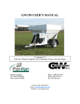
GW200C USER’S MANUAL
Par-Kan Company
2915 West 900 South
Silver Lake, IN 46982
Phone: 1-800-291-5487
Phone: 260-352-2141
Fax: 260-352-0701
Contact: Sales Department
E-mail: [email protected]
Website: www.par-kan.com
*** Important ***
Read User’s Manual Completely Prior to Operating, Towing, or Servicing Wagon
GW200C
CUSTOMER: __________________________________
SERIAL # _____________________________________
V.I.N. _________________________________________
WEIGH TRONIX SERIAL # _____________________
2
Grain-Weigh 200C Manual Table of Contents
Page 2 ............................................ Product Information
Page 3……………………………….. Table of Contents
Page 4………………………. ........... Warranty
Page 5 ............................................ Cart Dimensions
Page 6 ............................................ General Specifications & Features
Page 7 ............................................ Safety & Operating Precautions
Page 8-9 ......................................... Operation Procedures
Page 10 .......................................... Maintenance & Storage
Page 11 .......................................... Operation of Maintenance Meter
Page 12-15 ..................................... Trouble Shooting
Page 16 .......................................... Belt Alignment Procedure
Page 17 .......................................... Clean Out Procedure
Page 18-24 ..................................... Replacement Parts
Page 25 .......................................... Seed Tubes
Page 26-27 ..................................... Decals
Page 28-29 ..................................... Electrical Schematic
Page 30-32 ..................................... Hydraulic System
Page 33 .......................................... Towing Safety
Page 34-35 ..................................... Shurco Replacement Parts
Page 36 .......................................... Weigh Tronix™ Calibration Procedure
Page 37-40 ..................................... Weigh Tronix™ Adding LED Light Procedure
Page 41 .......................................... Contact Infomation
Additional User Manual’s
-Briggs & Stratton® Operator/Owner Manual
-Weigh Tronix™ Model 640 User’s Manual
-Shurco Owner’s Manual
-Wallace Forge
Note: This manual supersedes any other information supplied by Par-Kan Company before this date, and is good only for serial numbers listed in the
manual.
3
Par-Kan Company - Grain Weigh Division
Model GW-200C One Year Warranty
Par-Kan Company’s Grain-Weigh Equipment is warranted to the original purchaser to be free from defects in material and workmanship for a period of one year
from the date of purchase as dated on Grain-Weigh’s original invoice.
Grain-Weigh will replace during the warranty period, subject to an examination
by an authorized representative of Grain-Weigh, any warranted part which proves defective in material and/or workmanship under normal installation, use, and service.
Parts must be returned, and transportation charges prepaid to our factory. Any
changes to the Grain Weigh equipment as a result of modifications, misuse, abuse, neglect, accident, vandalism, fire, flood, other acts of God, or improper installation will
void this warranty. Treating seed in unit will void the warranty. Par-Kan is not responsibility with seed used in any unit.
If Par-Kan Grain-Weigh receives notice of any such defect during the warranty
period. Grain-Weigh will, at its discretion, repair or replace components which prove to
be defective. Other manufacturer’s warranties may apply for components installed on
Grain-Weigh equipment. Grain-Weigh makes no other warranty, either expressed or
implied, with respect to this product. Any special, incidental, or consequential damages arising from any breach of warranty are specifically excluded hereunder.
Manufacturer’s Warranties:
Axis Axles, 1 Year Warranty
Weigh Tronix™ Scale System, 3 Year Warranty
Briggs & Stratton® 18 H.P. Vanguard Engine, 2 Year Warranty
4
5
85”
102”
101 1/2”
102”
83 1/4”
24”
16”
23
170”
223”
106 1/2”
39”
117”
118 1/2”
Grain-Weigh 200C General Specifications & Features
1. Weigh Tronix™ Model 640 Farm Indicator – 2 lb. increment.
2. Briggs & Stratton®, 18 HP Vanguard Engine With Electric Start (Pull start backup system.)
3. 14,000 lb. Axis Tandem axle.
4. ST235//80 R16, 8-Bolt Tires
5. Capacity: 200 Bushels.
6. Hydraulically Driven Conveyor Belt
7. 2-5/16” Ball Coupler – rated at 14,000 lbs.
8. Standard Cart Has an Approximate Empty Weight of 4200 lbs. without options.
9. Tongue Jack with Swivel Wheel
10. Towing Vehicle Hitch MUST be Rated at 14,000 lbs.
11. 6-1/2 Gallon Plastic Gasoline Tank.
12. 8” wide X 2” cleated conveyor belt
13. 14,000 lb Towing Capacity Maximum
6
Grain Weigh 200C Safety and Operating Precautions
1. Observe all safety precautions listed in this manual
2. No riders
3. Stand clear of all moving parts while in operation.
4. Make no adjustments while cart is running.
5. Cart can be loaded without being hitched, but should be on level ground while loading.
6. Do not touch or allow unit to come in contact with overhead electrical wires.
7. Gasoline tank should not be filled while engine is running or hot.
8. “Conveyor Run” and “Belt Tension” switch must be turned off to store conveyor.
9. Consult the Briggs & Stratton engine manual for operating instructions before using.
10. Do not operate Briggs & Stratton® Engine over 3,000 RPM.
11. Do not transport with conveyor in raised position.
12. Proper height to top of 2-5/16” ball hitch on towing vehicle should not exceed recommended allowance of 23”
13. Do not load in excess of tire manufacturer ratings for either the GW200C cart or the towing
vehicle.
14. Towing vehicle should be of adequate capacity.
15. The total cart weight should not exceed 14,000 lbs.
16. Wheel lug nuts must be tight.
17. Never enter the bin at any time.
18. Be aware of all information, caution, warning, and danger signs on the unit.
19. Be aware of hot hydraulic fluid in case of a hydraulic line break.
20. Below 10 degrees F., change hydraulic oil to SAE 5W30 motor oil.
21. The operation of this cart must comply with all federal and state laws.
7
Grain-Weigh 200C Operating Procedures
1. Check engine oil and fuel before starting engine.
2. Run engine and hydraulic system for 5 minutes to pre-warm hydraulic fluid prior to
operating conveyor unit.
3. Refer to the Weigh Tronix Users Manual for details on key functions on the Model
640 Farm Indicator.
4. Weigh Tronix system will shut down if powered up prior to starting engine.
5. Receive grain into GW200C.
6. Record weight data for yield comparison if desired.
7. Toggle Switch #3 to the up position, to activate belt tension. Switch reference num
ber is starting from the top of the panel counting in a downward fashion.
8. Toggle and hold Switch #4 up to display conveyor. While conveyor is displaying,
operator must ensure belt cleats do not get pinched in the guard area.
9. Once conveyor is displayed, release Switch #4. Belt tension on pressure gauge
should be around 450—500 psi. Gauge is located on upper conveyor section.
10. Toggle switch #5 to either the fast or slow position depending upon delivery requirements. Fast speed is recommended for seed delivery.
11. Toggle switch #6 to the “conveyor run” position to activate conveyor.
12. Toggle and hold switch #2, to open seed door. A light will illuminate on the electrical panel (or the remote control) to indicate where the unit will deliver around 8 bu/
min. at the current seed door opening for seed delivery in slow speed. Release
switch to hold the seed door at preferred opening for use.
8
Grain-Weigh 200C Operating Procedures
13. Transfer grain to receiving vehicle. Record weight data for yield comparison if desired for seed tendering.
14. Once the desired amount of grain is delivered, toggle and hold switch #2 down to
close the seed door. Let the unit run 3 to 5 minutes after seed door is closed to assure remaining grain is cleared from the conveyor tube on the unit.
15. Toggle switch #6 down to “conveyor stop” position to deactivate conveyor belt.
16. Decrease engine rpm to idle throttle.
17. Turn off conveyor unit.
To Store Unit for Travel
1. Run engine and hydraulic system for 5 minutes to pre-warm hydraulic oil prior to
before loading system.
2. Toggle and hold down switch #2, to ensure seed door is closed.
3. Toggle switch #3 down, this will turn off the belt tension.
4. Toggle and hold switch #4 to the “Store Conveyor” position. Once conveyor is
stored, release switch.
5. Turn engine key to the off position. Unit is now ready for travel.
9
Grain-Weigh 200C Maintenance
Daily Check List:
-Check engine oil level (do not overfill).
-Fill gas tank for daily operation.
-Check for oil leaks.
-Check hydraulic oil level, do not overfill (SAE 10W30).
-Fill 80% full (9.5 gallons)
-Total Capacity: 12 gallons
-Inspect for loose nuts and bolts.
-Inspect for belt alignment and belt damage.
-Inspect and check that lights are working properly.
-Inspect safety chains for damaged.
-Grease top and bottom conveyor pulley bearings.
-Check tire pressure should be 80 PSI cold.
-Check and inspect for loose wheel lug nuts.
Seasonal Check List:
Inspect and pack wheel bearings.
Inspect for conveyor belt wear or damage.
Inspect discharge hood for excessive wear or damage.
Grease top and bottom pulley bearings.
Clean battery terminals.
Grease top conveyor hinge plate pin every 50 hours of operation.
Check Weigh Tronix for proper operation. (See Weigh Tronix manual.)
Service Briggs & Stratton engine. (See Briggs & Stratton manual.)
Empty gas tank for seasonal storage.
Change hydraulic filter after first 50 hrs of operation and every 300 hrs of operation, there after.
Wash and wax to maintain powder coat finish.
Check all fasteners for tightness.
10
Grain-Weigh 200C Operation of Maintenance Meter
Multi-Function Maintenance Meter: Hour Meter, Tachometer, and Service Alarm
Hour / Tachometer: These functions are fully automatic. Upon engine start the meter will
show rpm's. At engine shutdown the meter displays the total accumulated running time (which
cannot be reset).
Service Alarms: This function is also fully automatic. The meter has a dual flash alert displaying “CHG OIL & LUBE” at 25 operation hour intervals. The meter will begin flashing 1 hour before the 25 hour increment, and stop flashing 1 hour after.
Note: Consult the Briggs & Stratton Engine Manual for the engine’s proper maintenance
schedule. Also, consult this manual for the proper GW200C cart system maintenance schedule.
11
Grain-Weigh 200C Trouble Shooting
Problem
Cause
Test
Correction
Engine will not start
No fuel
Bad connections
Dead Battery
Starter
Visual
Meter
Meter
Meter
Add fuel
Clean or replace
Charge or replace
Repair or replace
Selective hydraulic components not
working (Conveyor Belt, Unloading
Door, or Conveyor Tube Display)
Hydraulic Oil
Visual
Add oil
Solenoid or Elec- Check the meter conFix faulty electrical contrical Connecnection or switch that is nection or switch
tions
not working correctly.
Hydraulic Components
Replace faulty hydraulic
component(s)
Conveyor will not display or store
Valve needs adjusted, cleaned,
or replaced
Visual
Adjust Valve or clean (see
page 14)
Fast Speed on conveyor low on torque
Valve needs adjusted, cleaned,
or replaced
Visual
Adjust Valve or clean (see
page 14)
Slow Speed on conveyor low on torque Valve needs adjusted, cleaned,
or replaced
Visual
Adjust Valve or clean (see
page 14)
Belt Tension pressure not correct
Valve needs adjusted, cleaned,
or replaced
Visual
Adjust Valve or clean (see
page 14)
Weigh Tronix will not power up
Blown fuse
Bad connections
Dead Battery
Other
Meter
Meter
Meter
Replace
Clean or replace
Charge or replace
See Weigh Tronix Manual
Incorrect weights
Weigh Bar
Wiring
Meter
See Weigh Tronix Manual
Repair or replace
*see pg. 10A for more
details.
Hydraulic oil overheating
Engine over
3,000 RPM
None
Keep engine at 3,000
RPM
All Hydraulics will not operate
Low on Hydraulic Visual
Oil
Add Oil
Blown Fuse
Replace 10 amp fuse behind weigh head.
Oil
Visual
Add Oil
12
Grain Weigh 200C Hydraulic Trouble Shooting
1. Hydraulics cease to operate.
- Verify engine is running at full power and not on one cylinder. Ensure vent on the gas cap is
open for engine to receive fuel.
- Check for blown fuse behind the weigh head or refer to manual for override procedure.
- Visually check that the correct amount of hydraulic oil is in the reservoir tank.
2. If conveyor fails to raise or lower.
- Verify engine is running within the normal rpm range. (3,000 rpm)
- Test manual override system on the front manifold for proper working conditions.
- Adjust the flow control valve on the backside of the manifold.
3. If conveyor does not raise or lower smoothly.
- Verify the engine is running in the normal rpm range. (3,000 rpm)
- Adjust the flow control valve on the backside of the manifold.
1
2
The pre set adjustment for this flow control valve has been set as follows: Twist knob clockwise
until snug, then twist counterclockwise 2 full revolutions and tighten down with 5/64” Allen
wrench.
13
Grain-Weigh 200C Trouble Shooting
If the top portion of the conveyor bounces
while it is being displayed or stored, valves #1
and #2 controls this part of the cart. By turning
the valve clockwise it will slow the action of
the conveyor. Likewise, turning the valve
counter clockwise, it will increase the action of
the conveyor.
Valve #1 controls the speed of the
upper conveyor being displayed. Screwing the
valve out will increase flow and speed.
Valve #2 controls the speed of the
upper conveyor being stored. Screwing the
valve out will increase flow and speed.
The top valve located on the opposite
side of manifold block is the pressure relief
valve for these two valves. Screwing the valve
in will increase the pressure relief.
1
2
To adjust any of these valves, loosen the 11/16” jam
nut and use a 3/16” Allen wrench to turn the valve
clockwise or counter clockwise. Turning the valve
clockwise will increase the torque or pressure of the
desired item. Likewise, turning the valve counter
clockwise will decrease the torque or pressure of the
desired item. To remove the valve, you will need a
7/8 wrench.
3
4
Valve #3 controls the storage and display of
the unit. Control valves are located on the front manifold, toward the front of the cart.
Valve #4 controls the Fast speed of the conveyor located in the same manifold block as valve #1.
Valve #5 controls the slow speed of the conveyor. The valve is located on the rear manifold, at the
rear of the cart.
Valve #6 controls the belt tension pressure.
It is located in the same manifold block as valve #5.
Turning the screw counter clockwise will decrease the
pressure and clockwise will increase the pressure.
5
6
14
Grain-Weigh 200C Trouble Shooting
Problem:
Cause:
Incorrect Weights
Check System
-Verify unit is level so the weighing system works correctly.
-Verify that the decal is on “TOP” of the weighing bars for correct installation.
-Please check and reference Appendix X Quick Programming Guide in your Avery WeighTronix manual and see if the Configuration Code Number (CCN) is properly entered for the
scale application. If not known, please consult Par-Kan for assistance.
-If Configuration Code Number (CCN) is entered properly do a visual inspection of the scale
system and check for:
-Cable damage to weigh bar cables or junction box cable
-Verify the supporting structure and weighing structure do not touch at any other point
except at the weigh bars.
-Next if the scale is still not weighing properly, check for faulty weigh bars as follows:
-Position a person or heavy object on the scale system above each weigh bar, one
weigh bar at a time, and compare the weight readings.
-All readings should be nearly identical to each other. If a reading is
significantly different from the other readings, weigh bar could be defective and should
be replaced.
-Find the cell that is not in the approximate weight as the other two and that is the bad cell. If
the cells are all approximately the same weight then a weigh head could be the issue. Please
contact Par-Kan Company to continue with this issue.
15
Grain-Weigh 200C Belt Alignment Procedure
Bottom Pulley Alignment
To align the belt on the lower pulley, first unbolt the bottom clean out door with a 9/16 deep well socket
and let the door rest on the ground. Next, put the conveyor in the run position with the belt running (see pages 89). Once the belt is running, visually inspect that the belt is running in the center of the pulley. DO NOT PUT
YOU HANDS NEAR THE BELT.
If the belt is not center on the pulley and is riding the left side of the conveyor, loosen the 3/4” nut on top
of the motor bracket. Use the same wrench, and turn the all-thread clockwise. At each full revolution of the allthread, inspect that the conveyor belt is center on the pulley. Once the belt is at the desired position, tighten both
3/4” nuts located on each side of the motor bracket to lock adjustment in place.
If the belt is riding on the right side of the conveyor, loosen the 3/4” nut on the bottom of the motor
bracket. Use the same wrench, and turn the all-thread counter clockwise. Once the belt is in the desired position,
tighten both 3/4” nuts located on each side of the motor bracket. Allow the belt to track for several minutes to ensure the belt is tracking on the center of the head pulley
Top Pulley Alignment
Top pulley has been factory aligned. Track the belt using only the threaded rod take up as referenced on
the “bottom pulley alignment” above.
16
Grain-Weigh 200C Conveyor Cleanout Procedure
To remove almost all the grain out of the conveyor unit, first put the conveyor in the run position without
running the unit (see pages 8-9). Once the unit is displayed, turn off the belt tension switch (3rd switch down)
and begin storing the conveyor, this will retract the belt tension cylinder. At this point, turn the unit off. Use a
9/16” deep well socket and unbolt the bottom clean out door, letting the door rest on the ground. Grab hold of the
belt cleats and pull them toward you, there should be slack in the belt for this to occur. By pulling the belt loose
from the conveyor tube, this will release any grain captured between the bottom of the belt and the conveyor tube.
To complete a thorough cleaning of the unit, start the unit and open the seed door to its full extension.
Turn off the conveyor unit and wash out the seed bin and conveyor belt. The water will drain out through the seed
clean out door.
Once the unit is cleaned the desired amount, re-attach the clean out door. Start the unit, and store the conveyor. Unit is ready for your next delivery.
DO NOT TREAT SEED IN UNIT. TREATING SEED IN UNIT WILL VOID WARRANTY. PARKAN HAS NO RESPONISBILITY WITH TREATING SEED IN UNIT.
17
Grain-Weigh 200C Axle & Hub Assembly
18
Grain-Weigh 200C Axle & Hub Parts Listing
Key #
Part Number
Description
1
241144
DL600 Seal
2
241145
Inner Bearing
3
241146
Inner Cone
4
241147
Left Hand Brake
4B
241148
Right Hand Brake
5
241149
Brake Drum
6
241150
Outer Cone
7
241151
Outer Bearing
8
241106
“D” Washer
9
241107
1-14 Slotted Jam Nut
10
241152
Tang Washer
11
241141
Dust Cap
12
241153
Rubber Plug for Dust Cap
13
241132
Cone Wheel Nut ½”
14
241154
U-Bolt – Zinc
15
241155
Tie Plate – Zinc
16
241156
½” Roll Lock Nut – Zinc
**
241157
Brake Mounting Bolts 3/8” x 1”
**
241158
Brake Mounting Lock Nuts 3/8”
**
241159
Brake Mounting Lock Washer 3/8”
**
241160
Brake Wiring Scotch-Lock Connectors
**
241161
Leaf Spring
**
241162
Beam Assembly ( Axle Beam, Spindles, Spring Pads, Brake Flanges )
* Items not shown if full assembled state.
19
Grain-Weigh 200C Engine and Fuel Tank
Key # Part Number
Description
1*
Assembled engine assembly. (Includes: ignition switch wiring, low oil shut
GW150-6-SA-002 off wiring, muffler guard, heat shield, parker pump, pump mount, motor oil,
battery cable. ) Does not include: throttle or choke cables
2
260100
Cable-Throttle
3
260110
Cable-Choke
4
GW150-7-SA-008
Gas Tank with fittings and hose assembled
5
220360
Gas line hose clamp
6
220319
Fuel hose, 1/4” I.D. X 20” length
7
220360
Gas line hose clamp
* Items not shown if full assembled state.
20
Grain-Weigh 200C Frame & Body ( Rear View )
Key #
Part Number
Description
1
660020
Tail light assembly kit ( Includes: taillight, grommet, and pigtail plug )
2
660010
License plate light
3
250069
Decal, Par-Kan Company Logo
4
660011
License plate bracket
5
250029
Reflector, 3” round red
6
250250
Decal, Made in the U.S.A
7
250100
Decal, Grain-Weigh
8
362024
Black Poly Fender—Tandem Axel
9
241204
Mud Flap
10
241083
Tire & Rim Assembly—GW200
11
GW200C-0W016
Fender Bracket Weldment
12
GW200A-1P601
Sample Door
21
Grain-Weigh 200C Frame & Body ( Front View )
22
Grain Weigh 200C Frame & Body ( Front View ) Continued
Key #
Part Number
Description
1
280057
Ball Coupler– 2-5/16”
2
270282
Safety Chains
3
GW200C-6W000
Ladder Weldment
4
280100
Tongue Jack with Swivel wheel
5
270013
Cam lock, (Grain-weigh box)
6
361559
Sight Glass Square
7
362077
Conveyor protector shield Blk GW200C
8
362035
Belt, Conveyor
9
220477
Pressure Gauge
10
430069
Hyd. Cyl. 2” X 36”, Push out arm / Belt Tension
11
640042
Switch, limit side mount roller / lever GW200C
12
430059
Hyd. Cyl. 2 1/2” X 36”, Std. Port GW200C / Conveyor Display
13
660012
Light, Weigh tronix box
14
620101
Tachometer
15
260005
Key Switch
16
260110
Choke Lever
17
260100
Throttle Lever
18
640195
Weigh Scale Head (Model 640 Weigh Tronix)
19
640024
Switch, Toggle SPST
20
640085
Indicator Light, LED
21
640022
Switch, Toggle SPTD
22
640021
Switch, Toggle SPDT
23
640059
Switch, Toggle DP-ST
23
Grain-Weigh 200C Top Shroud and Pulleys
Key #:
Part Number:
Description:
1
GW200C-3P300
Delivery Shroud Right
2
GW200C-3P301
Delivery Shroud Left
3
GW200C-3P302
Delivery Shroud Rear Cap
4
GW200C-3P303
Delivery Shroud Front Cap
5
362076
Conveyor, Delivery Shroud Black GW200C
6
280201
Bearing, Flange Type / 1” 2-Bolt
7
220499
Set-Screw Shaft Coupling 1”
8
231300
Roller, Primary 5-1/2" X 7-1/2" / Lagged
9
231301
Roller, Top 6” X 8” / Smooth
24
Grain-Weigh 200C Seed Tubes
Key Part Number
#
Key #
Description
1
GW200C-9A041 3 Section Seed Tube Assembly
2
362031
Seed Tube, Telescoping 5” D 3
Section
3
210075
Pop Rivet
4
361198
5” Flex Hose
5
220366
Hose Clamp, 6” Stainless Steel
6
362036
Seed Tube, Reducer-GW200C
7
362019
Seed Tube Adapter
Part Number
Description
9
GW200C-9W700
Top Conveyor Adapter Pin
10
217201
Washer, 3/8” USS Flat Zinc
11
210112
Hair Pin Clip
Key #
Part Number
12
GW200C-9A040
8” Flex Seed Tube Assembly
13
362019
Seed Tube Adapter
14
220367
Hose Clamp
15
362041
8” Flex Hose
16
210075
Pop Rivet
25
Description
Grain-Weigh 200C Decals
26
Grain-Weigh 200C Decals
Number:
Part Number:
Description:
1
250018
Decal, Warning, Keep Hands, Feet, Etc.
2
250101C
Decal, Toggle Switches
3
250051
Decal, Treated Seed
4
250104
Decal, Warning: Use 2-5/16” Ball E&S
5
250112
Decal, Caution: Pinch Point
6
250105
Decal, Warning: Read User’s Manual (GW)
7
250101B
Decal, Slow (Small)
8
250101D
Decal, Open (Large)
9
250101A
Decal, Fast (Small)
10
250101E
Decal, Close (Large)
11
250057
Decal, Be Careful Overhead Wires (No Arrow)
12
250027
Decal, Watch Your Step
13
250016
Decal, Be Careful Overhead Wires (Arrow)
14
With Roll Tarp
Decal, Roll Tarp Information
15
250063
Decal, Caution: Manual Replacement
16
250100
Decal, Grain Weigh (Small) Red/Black On White
17
250000
Decal, Par-Kan (6-1/4” X 4-1/2”)
18
250250
Decal, Made In The USA
19
250101F
Decal, 3000 RPM Maximum (Black Lettering)
27
Grain-Weigh 200C Electrical Schematic for Switch Panel
28
Grain-Weigh 200C Trailer Electrical Schematic
29
Grain Weigh 200C Hydraulic System
30
Grain Weigh 200C Hydraulic System
31
Grain Weigh 200C Hydraulic Parts Listing
Key #
Part Number
Description
1
420031
Hydraulic Adapter, #6FORB X 1/4” NPT
2
420015
Hydraulic Adapter Elbow, #6JIC X #6MP090
3
420022
Hydraulic Adapter, #12ORB X #12JIC
4
440611
Hydraulic Oil Filter with Spin on Cartridge
5
440024
Hydraulic Adapter, #12ORB X #12JICM Elbow
6
420024
Hydraulic Adapter, #12ORB X #12JICM
7
430070
2” X 30” GW200C Gate Cylinder
8
430069
2” X 36” GW200C Belt Cylinder
9
430059
2 1/2” X 36” STD Port Display Cylinder
10
440003
Manifold Block Assembly with Check Valve “Main”
11
440013
Manifold Block Assembly with Check Valve “Secondary”
12
430005
Hydraulic Tank
13
440000
1/4” Flow Control Valve
14
220579
Shaft Coupling (1”)
15
220581
Shaft Coupling—Spider
16
220580
Shaft Coupling (5/8”)
17
430009
Pump Mount—GW Adapter
18
440617
Hydraulic Flow Ezy Breather
19
440615
Hydraulic Strainer
20
430011
Hydraulic Motor
21
420011
Hydraulic Adapter, #12JIC X #10ORB
22
420055
Hydraulic Adapter, 1 5/16”JIC X 1 1/16ORB
23
410132
Hose, Small Manifold to Belt Cylinder, 1/4” X 168”
24
410137
Hose, Pressure Gauge to Cylinder, 1/4” X 22”
25
410126
Hose, Small Manifold to Large Manifold, 1/4” X 20”
26
410129
Hose, Small Manifold to T, 3/8” X 30”
27
410019
Hose, Large Manifold to Door Cylinder, 1/4” X 72”
28
410130
Hose, Large Manifold to Display Cylinder, 1/4” X 66”
29
410127
Hose, Hydraulic Pump to Small Manifold, 1/4” X 75”
30
410131
Hose, Large Manifold to Display Cylinder 1/4” X 102”
31
410014
Hose, Hydraulic Reservoir to Hydraulic Pump, 1” X 48”
32
410125
Hose, Large Manifold to T, 3/4” X 48”
33
410015
Hose, Hydraulic Pump to Large Manifold, 3/4” X 57”
34
410128
Hose, Large Manifold to Hydraulic Motor, 5/8” X 40”
35
430026
Hydraulic Pump
32
Grain Weigh 200C Towing Safety Appendix
Towing the Grain Weigh Cart is designed to be safe provided some basic precautions are taken. It is the
responsibility of the operator to ensure these procedures are followed for the safety of yourself and others on the
road. In addition, due to the variety of laws you should check local and/or state requirements.
Some common reasons for towing accidents include the following:
- Failure to properly connect the coupler and/or safety chains.
- Overloading trailer, towing vehicle, or safety devices.
- Towing with excessive speeds.
- Damaged or improperly maintained towing equipment.
Items to consider before towing the Grain Weigh 200C Cart:
-Check the payload rating on your towing vehicle(s), and equipment to ensure they can meet the requirements for
pulling this trailer.
- Regular inspections should be made to safeguard against failure due to damaged towing and safety equipment.
Some of these items include safety chains, hydraulic brake system, turn signals and taillights.
If one or more of the links or fittings on the safety chain is stretched, broken, or deformed it should be replaced.
Always replace entire chain assembly.
- Safety chains should be connected to the towing vehicle and trailer so the slack for each length of chain is approximately the same when the vehicles are aligned on a common front to rear centerline. There shall be no more
slack than necessary to permit proper turning of the vehicles. The safety chains shall be crossed under the trailer
tongue and connected to the hitch assembly of the towing vehicle.
Note: Crossing the chains under the tongue typically reduces the probability of stressing or breaking the chains
when turning.
Figure 3 – Standard Ball Coupler
33
Grain Weigh 200C Shurco Replacement Parts
34
Grain Weigh 200C Shurco Replacement Parts
Key #
Part Number
Description
1
361544
Crank Stand-Off 7”
2
361521
Tarp Stop
3
361529
Roll Return End plug – Nylon
4
361512
Trim Seal 110” long
5
361549
Roll Return Tube 46”
6
361546
Stretch Rope, 124” long
7
361542
Crank Arm Assembly
8
361548
Retainer Bushing
9
361541
Crank Retainer
10
361535
Rope Guard
11
361540
Roll Return Tube
12
361511
Font Bulkhead
13
361510
Rear Bulkhead
14
361539
Side Mount Latch
15
361538
Fixed Tube
16
361537
Ridge Pole
17
361536
Roll Tube with Spline
18
361530
Crank Extension
19
361534
Screw, 8-32: x 3.8” Self Tapping
20
361525
Protective Cap
21
361527
Cap Screw, 3/8” x 1-3/4”
22
361543
Cap Screw, ½” hex
23
361518
Screw, ¼” x ¾” Self Tapping
24
361547
Screw, 3/8” x 1” Self Tapping
25
361545
Hex Nut, 3-18”-16 Zinc
26
361533
Nut, 5/16” Hex
27
361550
Locknut, 3/8” – Centerlock
28
361532
Locknut, 5/16” – Nylon
29
361526
Flat Washer, 3/8”
30
361523
Lock Washer, 3/8”
31
361522
Spring Pin, 3/8” x 2’
32
361524
Nylon Truck Rivet
33
361516
Universal Round Insert, 1-1/8”
34
361520
Wire Lock Pin, 3/8” x 2-1/2”
35
361531
Eyebolt Anchor, 5/16” x 1”
36
361519
Protective Cap
37
361515
Splined U-Joint, 1-1/4” x 8”
38
361517
Plastic U-Clamp
39
361508
Tarp Only
40
361514
Tarp Cover Assembly with Poles & Tube
41
361509
Crank Assembly
35
Model 640 Weigh Tronix Calibration Procedure
Model: 640
1.
Press the On/Off button and the greeting “Hello” should arrear on the screen and then the scale will return to zero.
2.
From the G/N mode, press and hold the HOLD/MENU key for three beeps ( 3 sec. ) then release… SET.PAS is
displayed
3.
Press the RM button until the number 6 is displayed then press the HOLD/MENU button to move the cursor one
position.
4.
Press the RM button until the number 4 is displayed then press the HOLD/MENU button to move the cursor one
position.
5.
Press the RM button until the number 0 is displayed then press the PRINT/SELECT button once…CONFIG should
be displayed.
6.
Press the HOLD/MENU button until….SPAN is displayed
7.
Press the PRINT/SELECT button and now the current weight should be displayed.
8.
With either a calibrator or some known weight, put an appropriate weight onto the scale… and the current weight is
displayed.
9.
Press the RM key to increase the weight or the M+ key to decrease the weight accordingly.
10.
Once the appropriate weight value is shown, press the PRINT/SELECT button… SPAN should be displayed on the
screen.
11.
Press the G/N button until the indicator returns to the gross weighing mode. Calibration of the scale is then complete.
36
Model 640 Weigh Tronix Adding LED Light Procedure
37
Model 640 Weigh Tronix Adding LED Light Procedure
38
Model 640 Weigh Tronix Adding LED Light Procedure
39
Model 640 Weigh Tronix Adding LED Light Procedure
40
Contact Information
Par-Kan Company
2915 West 900 South
Silver Lake, IN 46982
Phone: 1-800-291-5487
Phone: 260-352-2141
Fax: 260-352-0701
Contact: Sales Department
E-mail: [email protected]
Website: www.par-kan.com
41