1
Tel: +1 843 669 44 11
Fax: +1 843 664 44 58
ESAB AB
SE-- 695 81 LAXÅ
SWEDEN
Phone +46 584 81 000
Fax +46 584 123 08
www.esab.com
POWERCUT 650
Portable Plasma Cutting System
Instruction Manual (EN)
ESAB Consoles:
ESAB P/N 0558005151 - 230V, 1/3-Phase, 50/60 Hz - "CE"
ESAB P/N 0558005152 - 400V, 3-Phase, 50/60 Hz - "CE"
ESAB P/N 0558007820 - 400V, 3-Phase, 50/60 Hz
0558005362
030210
Be sure this information reaches the operator.
You can get extra copies through your supplier.
caution
These INSTRUCTIONS are for experienced operators. If you are not fully familiar with the
principles of operation and safe practices for arc welding and cutting equipment, we urge
you to read our booklet, “Precautions and Safe Practices for Arc Welding, Cutting, and
Gouging,” Form 52-529. Do NOT permit untrained persons to install, operate, or maintain
this equipment. Do NOT attempt to install or operate this equipment until you have read
and fully understand these instructions. If you do not fully understand these instructions,
contact your supplier for further information. Be sure to read the Safety Precautions before installing or operating this equipment.
USER RESPONSIBILITY
This equipment will perform in conformity with the description thereof contained in this manual and accompanying labels and/or inserts when installed, operated, maintained and repaired in accordance with the instructions provided. This equipment must be checked periodically. Malfunctioning or poorly maintained equipment
should not be used. Parts that are broken, missing, worn, distorted or contaminated should be replaced immediately. Should such repair or replacement become necessary, the manufacturer recommends that a telephone
or written request for service advice be made to the Authorized Distributor from whom it was purchased.
This equipment or any of its parts should not be altered without the prior written approval of the manufacturer.
The user of this equipment shall have the sole responsibility for any malfunction which results from improper
use, faulty maintenance, damage, improper repair or alteration by anyone other than the manufacturer or a service facility designated by the manufacturer.
READ AND UNDERSTAND THE INSTRUCTION MANUAL BEFORE INSTALLING OR OPERATING.
PROTECT YOURSELF AND OTHERS!
96
table of contents
SECTIONTITLE
PARAGRAPH
SECTION 1
PAGE
SAFETY.........................................................................................................................99
SECTION 2
INTRODUCTION......................................................................................................................................101
2.0
General........................................................................................................................................................102
2.1
Scope...........................................................................................................................................................102
SECTION 3
INSTALLATION........................................................................................................................................103
3.0
General........................................................................................................................................................103
3.1
Equipment Required..............................................................................................................................103
3.2
Location......................................................................................................................................................103
3.3
Inspection...................................................................................................................................................103
3.4
Connections..............................................................................................................................................104
3.4.1
Primary Electrical Input Connections...............................................................................................104
3.5
Secondary Connections........................................................................................................................107
3.6
Assembling PT-31XLPC Consumable Parts....................................................................................108
SECTION 4OPERATION..............................................................................................................................................109
4.0
POWERCUT 650 Controls......................................................................................................................109
4.1
Cutting with the PT-31XLPC................................................................................................................111
4.2
Operating Techniques............................................................................................................................111
4.3
Common Cutting Problems.................................................................................................................113
SECTION 5
5.0
5.1
5.2
5.3
5.4
5.5
MAINTENANCE.......................................................................................................................................115
Inspection and Cleaning.......................................................................................................................115
Flow Switch................................................................................................................................................115
Troubleshooting......................................................................................................................................116
Troubleshooting Guide.........................................................................................................................117
Sequence of Operation.........................................................................................................................121
Re-fitting the PT-31XLPC Torch...........................................................................................................123
SECTION 6REPLACEMENT PARTS.........................................................................................................................305
6.0
General........................................................................................................................................................305
6.1
Ordering......................................................................................................................................................305
97
table of contents
98
section
1safety
precautions
4&$5*0/
4"'&5:13&$"65*0/4
4BGFUZ1SFDBVUJPOT
GB
6TFSTPG&4"#XFMEJOHBOEQMBTNBDVUUJOHFRVJQNFOUIBWFUIFVMUJNBUFSFTQPOTJCJMJUZGPSFOTVSJOHUIBUBOZPOF
XIPXPSLTPOPSOFBSUIFFRVJQNFOUPCTFSWFTBMMUIFSFMFWBOUTBGFUZQSFDBVUJPOT4BGFUZQSFDBVUJPOTNVTUNFFU
UIFSFRVJSFNFOUTUIBUBQQMZUPUIJTUZQFPGXFMEJOHPSQMBTNBDVUUJOHFRVJQNFOU5IFGPMMPXJOHSFDPNNFOEBUJPOT
TIPVMECFPCTFSWFEJOBEEJUJPOUPUIFTUBOEBSESFHVMBUJPOTUIBUBQQMZUPUIFXPSLQMBDF
WARNING
"MMXPSLNVTUCFDBSSJFEPVUCZUSBJOFEQFSTPOOFMXFMMBDRVBJOUFEXJUIUIFPQFSBUJPOPGUIFXFMEJOHPSQMBTNB
Arc welding and cutting can be injurious to yourself and others. Take precausions when welding.
DVUUJOHFRVJQNFOU*ODPSSFDUPQFSBUJPOPGUIFFRVJQNFOUNBZMFBEUPIB[BSEPVTTJUVBUJPOTXIJDIDBOSFTVMUJO
Ask for your employer’s safety practices which should be based on manufacturers’ hazard data.
JOKVSZUPUIFPQFSBUPSBOEEBNBHFUPUIFFRVJQNFOU
ELECTRIC SHOCK - Can kill
S
Install and earth the welding unit in accordance with applicable standards.
"OZPOFXIPVTFTXFMEJOHPSQMBTNBDVUUJOHFRVJQNFOUNVTUCFGBNJMJBSXJUI
S
Do not touch live electrical parts or electrodes with bare skin, wet gloves or wet clothing.
JUTPQFSBUJPO
S
Insulate yourself from earth and the workpiece.
S
Ensure your working stance is safe.
MPDBUJPOPGFNFSHFODZTUPQT
FUMES AND GASES - Can be dangerous to health
JUTGVODUJPO
S
Keep your head out of the fumes.
SFMFWBOUTBGFUZQSFDBVUJPOT
S
Use ventilation, extraction at the arc, or both, to take fumes and gases away from your breathing zone
XFMEJOHBOEPSQMBTNBDVUUJOH
and the general area.
ARC RAYS - Can injure eyes and burn skin.
5IFPQFSBUPSNVTUFOTVSFUIBU
S
Protect your eyes and body. Use the correct welding screen and filter lens and wear protective
clothing.
OPVOBVUIPSJ[FEQFSTPOTUBUJPOFEXJUIJOUIFXPSLJOHBSFBPGUIFFRVJQNFOUXIFOJUJTTUBSUFEVQ
S
Protect bystanders with suitable screens or curtains.
OPPOFJTVOQSPUFDUFEXIFOUIFBSDJTTUSVDL
FIRE HAZARD
S
Sparks (spatter) can cause fire. Make sure therefore that there are no inflammable materials nearby.
5IFXPSLQMBDFNVTU
NOISE - Excessive noise can damage hearing
CFTVJUBCMFGPSUIFQVSQPTF
S
Protect your ears. Use earmuffs or other hearing protection.
CFGSFFGSPNESBGUT
S
Warn bystanders of the risk.
MALFUNCTION - Call for expert assistance in the event of malfunction.
1FSTPOBMTBGFUZFRVJQNFOU
Read and understand the instruction manual before installing or operating.
"MXBZTXFBSSFDPNNFOEFEQFSTPOBMTBGFUZFRVJQNFOUTVDIBTTBGFUZHMBTTFTnBNFQSPPG
PROTECT YOURSELF AND OTHERS!
DMPUIJOHTBGFUZHMPWFT
%POPUXFBSMPPTFmUUJOHJUFNTTVDIBTTDBSWFTCSBDFMFUTSJOHTFUDXIJDIDPVMECFDPNF
USBQQFEPSDBVTFCVSOT
(FOFSBMQSFDBVUJPOT
.BLFTVSFUIFSFUVSODBCMFJTDPOOFDUFETFDVSFMZ
WARNING!
8PSLPOIJHIWPMUBHFFRVJQNFOUNBZPOMZCFDBSSJFEPVUCZBRVBMJmFEFMFDUSJDJBO
Read and understand the instruction manual before installing
"QQSPQSJBUFmSFFYUJORVJTIJOHFRVJQNFOUNVTUCFDMFBSMZNBSLFEBOEDMPTFBUIBOE
or operating.
-VCSJDBUJPOBOENBJOUFOBODFNVTUOPUCFDBSSJFEPVUPOUIFFRVJQNFOUEVSJOHPQFSBUJPO
CAUTION!
CAUTION
Class A (400V CE) equipment is not intended for use in resi-
Class
A equipment
not intended
for use in
residential
locations
dential
locationsiswhere
the electrical
power
is provided
bywhere
the
the
electrical
power
is
provided
by
the
public
low-voltage
supply
public low-voltage supply system. There may be potential difsystem. There may be potential difficulties in ensuring electromagnic
ficulties inofensuring
electromagnetic
compatibility
Class A
compatibility
class A equipment
in those locations,
due toofconducted
in those
locations due to conducted as well as radiasequipment
well as radiated
disturbances.
ated disturbances.
99
Do not dispose of electrical equipment together with normal waste!
section
1safety
precautions
4&$5*0/
4"'&5:13&$"65*0/4
8"3/*/(
8&-%*/("/%1-"4."$655*/($"/#&*/+63*06450:0634&-'"/%
05)&34 5",& 13&$"65*0/4 8)&/ 8&-%*/( 03 $655*/( "4, '03
:063 &.1-0:&34 4"'&5: 13"$5*$&4 8)*$) 4)06-% #& #"4&% 0/
."/6'"$563&34)";"3%%"5"
&-&$53*$4)0$,$BOLJMM
*OTUBMMBOEFBSUIHSPVOE
UIFXFMEJOHPSQMBTNBDVUUJOHVOJUJOBDDPSEBODFXJUIBQQMJDBCMFTUBOEBSET
%POPUUPVDIMJWFFMFDUSJDBMQBSUTPSFMFDUSPEFTXJUICBSFTLJOXFUHMPWFTPSXFUDMPUIJOH
*OTVMBUFZPVSTFMGGSPNFBSUIBOEUIFXPSLQJFDF
&OTVSFZPVSXPSLJOHTUBODFJTTBGF
'6.&4"/%("4&4$BOCFEBOHFSPVTUPIFBMUI
,FFQZPVSIFBEPVUPGUIFGVNFT
6TFWFOUJMBUJPOFYUSBDUJPOBUUIFBSDPSCPUIUPUBLFGVNFTBOEHBTFTBXBZGSPNZPVSCSFBUIJOH[POF
BOEUIFHFOFSBMBSFB
"3$3":4$BOJOKVSFFZFTBOECVSOTLJO
1SPUFDUZPVSFZFTBOECPEZ6TFUIFDPSSFDUXFMEJOHQMBTNBDVUUJOHTDSFFOBOEmMUFSMFOTBOEXFBS
QSPUFDUJWFDMPUIJOH
1SPUFDUCZTUBOEFSTXJUITVJUBCMFTDSFFOTPSDVSUBJOT
'*3&)";"3%
4QBSLTTQBUUFS
DBODBVTFmSF.BLFTVSFUIFSFGPSFUIBUUIFSFBSFOPJOnBNNBCMFNBUFSJBMTOFBSCZ
/0*4&&YDFTTJWFOPJTFDBOEBNBHFIFBSJOH
1SPUFDUZPVSFBST6TFFBSNVõTPSPUIFSIFBSJOHQSPUFDUJPO
8BSOCZTUBOEFSTPGUIFSJTL
."-'6/$5*0/$BMMGPSFYQFSUBTTJTUBODFJOUIFFWFOUPGNBMGVODUJPO
3&"%"/%6/%&345"/%5)&*/4536$5*0/."/6"-#&'03&*/45"--*/(0301&3"5*/(
1305&$5:0634&-'"/%05)&34
100
section 2
INTRODUCTION
POWERCUT ® 650 Cutting Package
•
•
•
•
•
•
•
•
•
•
•
•
•
•
•
Manually cuts 15.9mm (5/8 inch) and severs 19.1mm (3/4
inch) - powerful cutting performance
Economical price - tremendous cutting value for the
money
Compact portable design - goes to the job, easily moved
about
Delivers big machine cutting power in a rugged,
lightweight package.
Arrives ready to cut, with torch connected and front-end
parts in place, for the ultimate in operator convenience.
High frequency starting - starts through paint
Trigger lock-in for long-cut operator comfort.
Adjustable output - tailor the current to the material being
cut
Compact simple torch - easy access, little maintenance
New quick - connect torch switch plug
New durable torch cable prevents snagging on fixtures
and materials
Patented XT nozzles - extended shape gives good visibility as well as good consumable life
Drag or standoff cutting - easy operation with little or no training
Template following feature - easily duplicates curves or
straight lines
Tolerates poor power lines
The POWERCUT® 650 comes out of the box ready to go! The torch is attached with parts in place, primary cord is attached and the filter/regulator
is installed. Just hook up the air, plug it in and cut.
POWERCUT® 650 / PT-31XLPC Cutting Performance
40 Amp
SPEED / Minutes
Specifications
Cuts 15.9mm (5/8 in.); severs 19.1mm (3/4 in.)
Output: 40% duty cycle...........................................................40A/120V
60% duty cycle...........................................................30A/120V
100% duty cycle........................................................22A/120V
Output Current Range................................................................ 10 to 40 Amperes
Open Circuit Voltage 290 Vdc Nominal
Input @ 40A/120V .........................230 vac 1/3 ph. 50/60 Hz., 37/20 amps
Input @ 40A/120V ......................................400 vac 3 ph. 50/60 Hz., 9 amps
Mild Steel
Cut Speeds
400V CE Mains Supply ...................................................................... Ssc min 1.3MVA
...................................................................................................................... Zmax 0.118Ω
Power factor @ 40A Output..............................................................76% (1 Phase)
Efficiency @ 40A Output.....................................................................85% (Typical)
Air requirements ........................... 118 l/m @ 5.5 bar (250 cfh at 80 psig)
Dimensions:
Length...............................................................406mm (16.00")
w/ handles..................................................653mm (25.70")
Height................................................................416mm (16.38")
Width.................................................................318mm (12.50")
w/ Opt. torch wrap..................................394mm (15.50")
Weight (less torch & work cable).................................................... 24 kg (53 lbs.)
How To Order
THICKNESS
The POWERCUT® 650 comes complete with everything you need:
console, 7.6m (25 ft.) PT-31XLPC torch, torch spare parts kit, air
filter/regulator, input power cord with plug, 7.6m (25 ft.) work cable
with clamp. System arrives fully assembled and ready to cut.
400V CE Mains Supply, Ssc min
Minimum short circuit power on the network in accordance with
IEC61000-3-12.
Ordering Information
POWERCUT ® 650 / 7.6m (25 ft.) PT-31XLPC "CE" package
400V CE Mains Supply, Zmax
Maximum permissible line on the network impedance in accordance
with IEC61000-3-11.
POWERCUT® 650,
230 vac 1/3 ph. 7.6m (25 ft.) PT-31XLPC - "CE"..................... 0558004800
400 vac 3 ph. 7.6m (25 ft.) PT-31XLPC - "CE"......................... 0558004801
400 vac 3 ph. 7.6m (25 ft.) PT-31XLPC..................................... 0558007821
Instruction Literature P/N.................................................................. 0558005362
101
section 2
Optional Accessories
Torch Guide Kits
The Deluxe kit, in a rugged plastic carrying case, includes
attachments for circle and straight line cutting on ferrous and
non-ferrous metals
Deluxe: 44.5mm - 1,066.8mm (1 3/4" - 42") Radius........... 0558003258
Basic: 44.5mm - 711.2mm (1 3/4" - 28") Radius................... 0558002675
Plasma Flow Measuring Kit
This valuable troubleshooting tool allows measurement of
the actual plasma gas flow through the torch.....0558000739 (19765)
Input Receptacle
230vac/50Amp, 3 Prong.........................................................................674540
INTRODUCTION
PT-31XLPC Replacement Torch.......................................... 0558005393
Torch comes assembled with Long "CE" Heat Shield, Nozzle, Electrode,
and Swirl Baffle.
PT-31XLPC Spare Parts Kit (P/N 0558005392) includes:
Heat Shield, Long (1)...........................................................0558000509 (36284)
Nozzles, High Performance (3)........................................0558000512 (20860)
Swirl Baffle (1)........................................................................0558000506 (20463)
Electrodes (2).........................................................................0558000507 (20862)
Plunger
0558000511
(20324)
Electrode
0558000507
(20862)
Torch Body
*0558000790
(20072)
Nozzle
0558000512
(20860)
Seat
0558000510
Swirl Baffle
(19679)
0558000506
(20463)
Heat Shield
0558000509
*Includes the following items:
(36284)
Seat - 0558000510 (19679)
O-ring - 0558000514 (950790)
Torch Wrap and Spare Parts Kit Holder
This enables operator to store S/P Kit, wrap torch and
work cable for easy transport and storage............................ 0558003398
WARNING
Do not use any torch with this power source
other than the ESAB brand PT-31XLPC
torch. Serious injury may occur if used with
any other torch.
Wheel Kit
For easy transport of system....................................................... 0558003399
2.0 General
The POWERCUT 650 is a compact, completely self-contained
plasma cutting system. As shipped, the system is fully assembled and ready to cut after being connected to input
power and a source of prefiltered compressed air (6.2-10.3
bar / 90-150 psig). The POWERCUT 650 package uses the
PT-31XLPC torch to deliver cutting power for materials up
to 15.9mm (5/8-in.) thick or for severing up to 19.1mm
(3/4-in.) thick.
2.1 scope
POWERCUT shown with Optional Torch Wrap
and Spare Parts Kit Holder installed.
The purpose of this manual is to provide the operator
with all the information required to install and operate the
POWERCUT 650 plasma arc cutting package. Technical reference material is also provided to assist in troubleshooting
the cutting package.
102
section 3installation
3.0General
Proper installation can contribute materially to the satisfactory and trouble-free operation of the POWERCUT
650 cutting package. It is suggested that each step in this section be studied carefully and followed as
closely as possible.
3.1 Equipment Required
A source of clean, prefiltered dry air that supplies 118 l/m @ 5.5 bar (250 cfh at 80 psig) is required for the
cutting operation. The air supply should not exceed 10.3 bar (150 psig), the maximum inlet pressure rating
of the air filter-regulator supplied with the package.
3.2Location
Adequate ventilation is necessary to provide proper cooling of the POWERCUT 650 and the amount of dirt,
dust, and excessive heat to which the equipment is exposed, should be minimized. There should be at least
one foot of clearance between the POWERCUT 650 power source and wall or any other obstruction to allow
freedom of air movement through the power source.
Installing or placing any type of filtering device will restrict the volume of intake air, thereby subjecting the
power source internal components to overheating. The warranty is void if any type of filter device is used.
3.3 Inspection
A.
Remove the shipping container and all packing material and inspect for evidence of concealed damage which may not have been apparent upon receipt of the POWERCUT 650. Notify the carrier of any
defects or damage at once.
B.
Check container for any loose parts prior to disposing of shipping materials.
C.
Check air louvers and any other openings to ensure that any obstruction is removed.
103
section 3installation
WARNING
ELECTRIC SHOCK CAN KILL! Precautionary measures should be taken to provide
maximum protection against electrical
shock. Be sure that all power is off by
opening the line (wall) disconnect switch
and by unplugging the power cord to the
unit when connections are made inside of
the power source.
caution
Be sure that the power source is properly
configured for your input power supply.
DO NOT connect a power source configured
for 230 V to a 460 V input power supply.
Damage to the machine may occur.
3.4
Connections
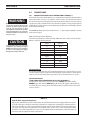
3.4.1
Primary Electrical Input Connections (Figure 3.1)
A line (wall) disconnect switch with fuses or circuit breakers should be provided at the
main power panel (see Fig. 3-1 and Table 3-1 for fuse sizes). The input power cable of
the console may be connected directly to the disconnect switch or you may purchase
a proper plug and receptacle from a local electrical supplier. If using plug/receptacle
combination, see Table 3-1 for recommended input conductors for connecting receptacle
to line disconnect switch.
The POWERCUT 650 power source with 230 vac, 1 / 3 -phase input capability is factory
set for 230 vac input.
NOTE: PC-650 input cable differences
The colors of input phases of the CE models differ from those of the “non CE” models.
Below is a table comparing the two:
Input
Standard
L1
L2
L3
Black
Red
White
GND
Green
Input
CE
L1
L2
L3
Brown
Grey
Black
GND
Green/Yellow
400 & 460-Volt CE
For the 400 and 460-Volt units, it isn’t important which leg is connected to L1, L2 and
L3, when 3-Phase input is used, however if inputting 1 phase power, L2 will be the unused leg. The T2 must have power to operate and it is connected across L1 and L3.
208/230-Volt models
**FOR SINGLE-PHASE CONNECTION OF 230-Volt CE MODELS:**
If single-phase connection is desired, connect the BLACK leg to “L3” and the
BROWN leg to “L1” with the GREY (L2) leg disconnected, lugged, and taped back.
, L2 will be the un-used leg. The T2 must have power to operate and it is connected
across L1 and L3.
NOTE !!!
400V CE Mains Supply Requirements:
High power equipment may, due to the primary current drawn from the mains supply, influence the power quality of the grid. Therefore connection restrictions or requirements regarding the maximum permissible mains impedance or the required minimum supply capacity at the interface point to the public grid
may apply for some types of equipment (see technical data). In this case it is the responsibility of the
installer or user of the equipment to ensure, by consultation with the distribution network operator if
necessary, that the equipment may be connected.
104
section 3installation
The Powercut 650 “CE model” is available as 230 vac single-phase power, or as 400 vac 3 phase.
Note: The 400 vac 3 phase unit is designed to work best when 3 phase input power is used, however with a slight de-rating
of the machine output, the PC-650 can be used on single phase.
Reasons for de-rating:
Input diode stress. 1 phase uses 4 diodes at higher current levels
Buss capacitors will see higher ripple currents
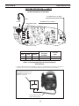
Connecting PC-650 for 208 vac input:
1. Unplug the unit from the primary input power.
2. Remove the left side panel by removing the rear handle and sliding the cover forward from the aluminum frame
rail.
3. Locate the input bridge (IBR) and the two-position terminal block on the left side of the unit towards the rear
panel. Locate the gray wire connected to TB5-2 and to IBR terminal “R”. For 208 vac input, disconnect the gray wire
from TB5-2 and then firmly connect it to TB5-1.
4. Locate the output bridge (D1) on the left side towards the front panel. Disconnect and swap leads X2 and X3 from
the main transformer. For 208 vac input, X2 is connected to TB3 and X3 is connected to terminal 3 of D1. Make sure
the connections are firmly tightened.
5. Leave all other wires the same.
6. Reinstall cover by sliding it back into the frame rail. Connect the rear handle and connect the Powercut 650 to the
208 vac input power.
208 V CONFIGURATION
NOTE:
FOR 208 vac MOVE GREY WIRE FROM TB5-2 TO TB5-1, MOVE T1 LEAD X2 TO TB3 AND T1 LEAD X3 TO D1-3.
Do NOT change any other wires.
X2 HERE FOR 208 vac INPUT
GRAY
208 vac
X3 HERE FOR 208 vac INPUT
INPUT BRIDGE (IBR)
BLACK
BLACK
GRAY
105
section 3installation
FACTORY SET FOR 230 vac INPUT
Do NOT change any other wires.
X3 HERE FOR 230 vac INPUT
GRAY
230 vac
INPUT BRIDGE (IBR)
X2 HERE FOR 230 vac INPUT
BLACK
BLACK
GRAY
Rated Input
Volts
Amp
Phases
Input & GND
Conductor
CU/AWG*
230
37/20
1/3
No. 6mm
50/40
400
9
3
No. 4mm
15
Fuse Size
Amps
Table 3.1. Recommended Sizes for Input Conductors
and Line Fuses
* Sized per National Code for 80°C rated copper conductors @ 30°C ambient. Not more than three conductors in
raceway or cable. Local codes should be followed if they specify sizes other than those listed above.
CUSTOMER FUSED LINE DISCONNECT SWITCH (See Table 3.1 and
WARNING in regards to chassis
ground in Section 3.4)
Factory supplied primary
power cable with plug.
Figure 3.1 Customer Fused Line Disconnect and Receptacle
106
section 3installation
3.5 SECONDARY CONNECTIONS (Refer to Fig. 3.3)
WARNING
Before making any connections to the
power source output terminals, make sure
that all primary input power to the power
source is deenergized (off) at the main
disconnect switch and that the input power
cable is unplugged.
WARNING
1. The POWERCUT 650 is supplied from the factory with the complete PT-31XLPC
torch and the work cable with clamp assembly pre-installed. No further installation is required. For information on torch connections or refitting the torch
(see Sec. 5.4).
2. Connect your air supply to the inlet connection of the filter-regulator.
3. Clamp the work cable to the workpiece. Be sure the workpiece is connected
to an approved earth ground with a properly sized ground cable.
Grounded Work
Table
ELECTRIC SHOCK CAN KILL! Precautionary
measures should be taken to provide maximum protection against electrical shock.
Be sure that all power is off by opening
the line (wall) disconnect switch and by
unplugging the power cord to the unit
when reconnecting for 208 vac input.
Be sure work is
in good contact
with the table
Earth Ground
Work Cable
Air Pressure
Adjustment Knob
Air Supply Connection
Moisture Bleed
Screw
Air Supply
250cfh @ 80 psig
Figure 3.3 Secondary Connections Diagram
107
section 3installation
WARNING
Make sure power switch on power source
is in OFF position and primary input power
is deenergized.
WARNING
BE SURE to install the swirl baffle in the
torch. Failure to do so would allow the
nozzle (tip) to contact the electrode.
This contact would permit high voltage
to be applied to the nozzle. Your contact
with the nozzle or workpiece could then
result in serious injury or death by
electric shock.
3.6 ASSEMBLING PT-31XLPC CONSUMABLE PARTS
The PT-31XLPC Torch is supplied complete; ready to cut and needs no further
assembly. If it becomes necessary to inspect the front end wear parts, see Figure
3.4 for correct assembly order.
Install the electrode, baffle, nozzle, and heat shield as shown in Fig. 3.4. Tighten heat
shield snugly but do not overtighten.
Torch Body
Electrode
0558000507
(20862)
*0558000790
(20072)
Swirl Baffle
0558000506
(20463)
WARNING
The PT-31XLPC torch head contains a gas
flow check valve that acts in conjunction
with the flow switch and circuitry within
the power source. This system prevents
the torch from being energized with high
voltage if the torch switch is accidentally
closed when the shield is removed. ALWAYS REPLACETORCHWITHTHE PROPER
TORCH MANUFACTURED BY ESAB SINCE
IT ALONE CONTAINS ESAB’S PATENTED
SAFETY INTERLOCK.
Nozzle
0558000512
(20860)
*Includes the following items:
Seat - 0558000510 (19679)
O-ring - 0558000514 (950790)
Heat Shield
0558000509
(36284)
NOZZLE, SWIRL BAFFLE AND ELECTRODE IN PLACE READY FOR INSTALLATION OF HEAT SHIELD.
Figure 3.4 Assembly of “XT” Consumable Parts
108
section 4
operation
B. POWER LIGHT
(WHITE)
REAR VIEW
H. FAULT LIGHT
(AMBER)
E. AIR
PRESSURE
GAUGE
F. AIR PRESSURE
CONTROL KNOB
C. CURRENT
CONTROL
KNOB
D. AIR
TEST SWITCH
G. TRIGGER LOCK
SWITCH
A. POWER ON-OFF
(I-O) SWITCH
FRONT VIEW
Figure 4.1. POWERCUT 650 Controls
WARNING
ELECTRIC SHOCK can kill.
• Do NOT operate the unit with the cover
removed.
• Do NOT apply power to the unit while
holding or carrying the unit.
• Do NOT touch any torch parts forward
of the torch handle (nozzle, heat shield,
electrode, etc.) with power switch on.
WARNING
4.0 POWERCUT 650 CONTROLS (FIGURE 4.1)
A. Power Switch (located on rear panel). When placed in ON position, the white
pilot light will glow indicating control circuit is energized and the cooling fan
will run. The POWERCUT 650 is now in the "READY" mode given a suitable air
supply and a properly assembled torch.
B. Power Light. Indicates that the Power Switch is in the ON position.
C.Output Current Control. Adjustable from 10 to 40 amperes to suit cutting
conditions.
D. Air Check Switch. When placed in ON position, air filter-regulator can be adjusted to desired pressure (5.5 bar / 80 psig) before cutting operations. Allow air
to flow for a few minutes. This should remove any condensation that may have
accumulated during shutdown period. Be sure to place switch in OFF position
before starting cutting operations.
E. Air Pressure Gauge. Indicates supply pressure to the unit.
F. Air Regulator Control Knob. Used to adjust the air pressure for the cutting
process. Proper operating range for the POWERCUT 650 is 5.5 bar (80 psig).
ARC RAYS can burn eyes and skin;
NOISE can damage hearing.
• Wear welding helmet with No. 6 or 7
lens shade.
• Wear eye, ear, and body protection.
G.Lock-In Switch. When placed in ON position, permits releasing torch switch
button after cutting arc has been initiated. To extinguish arc at end of cut, press
and release torch switch button again or pull torch away from work. When placed
in OFF position, torch switch must be held closed by the operator during the
entire cutting operation and then released at the end of cut.
109
section 4
operation
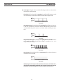
H.Fault Light. Will glow amber under the following conditions and operations
will come to a complete stop.
Flow Fault: The fault light will be mostly on but will flick off for approx.1/10th
of a second every second. This indicates that the air flow supply is low.
ON
OFF
0
1
2
Seconds
3
Over Temperature: The fault light will be mostly off but will flick on for approx.
1/10th of a second every second. This indicates that the duty cycle has been
exceeded. Allow the power source to cool down before returning to operation.
ON
OFF
0
3
1
2
Seconds
High/Low Line Voltage: The fault light will rapidly blink on and off (five times
per second). This indicates that the input voltage is outside the “+ or -” 15%
range of the input rating.
ON
OFF
0
1
2
Seconds
3
Over-Current: The fault light will be on continuously. This indicates that input
current has been exceeded.
ON
OFF
0
1
2
Seconds
3
All fault signals will remain on for a minimum of 10 seconds. If fault clears,
all will reset automatically except for over-current. To clear over-current,
the power must be shut off for 5 seconds and then turned back on.
110
section 4
operation
WARNING
Wear the usual protective gloves, clothing, and helmet. Helmet with filter lens
shade No. 6 or 7 should provide adequate
protection for your eyes.
WARNING
Never touch any parts forward of the
torch handle (tip, heat shield, electrode,
etc.) unless the power switch is in the
OFF position.
WARNING
Position the POWERCUT 650 at least 10
feet (3 meters) from the cutting area to
protect the unit from sparks and hot slag
from the cutting operation.
TOO FAST
TOO SLOW
CORRECT
Fig. 4.2 - Effect of Cutting Speed
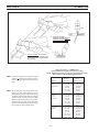
4.1 CUTTING WITH THE PT-31XLPC
After placing the primary (wall) switch to the ON position and making control and
air pressure adjustments as described above, proceed as follows:
1. Touch the tip of the torch to the workpiece (or within 0.5mm / 0.02in. of the
workpiece) holding the torch at about 15- 30° angle to avoid damaging the tip.
2. Depress the torch switch. (Air and high frequency should energize.)
3. Two seconds after depressing torch switch, the plasma arc will start cutting. (If
using the LOCK-IN mode, torch switch can be released after establishing the cutting arc.)
4. After starting the cut, the tip can be dragged along the workpiece if cutting up
to 6.4mm (1/4") thick material. When cutting material greater than 6.4mm (1/4"),
maintain a 3.2mm (1/8") tip-to-work (standoff ) distance.
5. When ending a cut, the torch switch should be released (press and release if
using LOCK-IN mode) and lifted off the workpiece just before the end of the cut
to minimize double-arcing which can damage the tip. This is to prevent high
frequency from reigniting after cutting arc extinguishes.
6. In the postflow mode, the arc can be restarted immediately by depressing the
torch switch. The two second preflow will automatically cancel.
4.2OPERATING TECHNIQUES
1. Piercing - Materials (up to 3.2mm / 1/8in. thick) may be pierced with the torch
touching the work. When piercing thicker materials (up to 4.8mm / 3/16in. aluminum or 6.4mm / 1/4in. stainless or carbon steel) at an angle, position the torch
0.5mm (.02") above the workpiece. Start the cutting arc, then immediately raise
the torch to 1.6mm (1/16") stand-off and move the torch along the cut path. This
will reduce the chance of spatter from entering the torch and prevent the possibility of welding the tip to the plate. The torch should be angled at about 30°
when starting to pierce, and then straightened after accomplishing the pierce.
2.Grate Cutting - For rapid restarts, such as grate or heavy mesh cutting, do not
release the torch switch. This avoids the 2 second preflow portion of the cutting
cycle.
111
section 4
operation
2
1
WHEN THE ARC BREAKS
THROUGH THE WORK, BRING THE
TORCH TO AN UPRIGHT POSITION AND PROCEED TO CUT.
TO START A PIERCE, TILT THE TORCH
TO PREVENT MOLTEN MATERIAL FROM
COMING BACK AGAINST AND DAMAGING THE TORCH.
Figure 4.3. Piercing Technique using the PT-31XLPC
Cutting Speed Range — POWERCUT 650
(Using Air with XT Consumables 40A @ 5.2 bar / 75 psig)
Nozzle - P/N 0558000512 (20860 ), Electrode - P/N 0558000507 (20862)
With 1.6mm (1/16" ) Standoff (Tip to Work Distance)
NOTE: Lower the air pressure to 5.2 bar (75 psig) on
materials < 1.6mm (1/16") or when inconsistent arc starting is experienced at 5.5 bar (80
psig).
Thickness
Material
(mm / in.)
NOTE: The speeds given here are typical for best
quality cuts. Your actual speeds may vary
depending on material composition, surface
condition, operator technique, etc. If cutting
speed is too fast, you may lose the cut. With
slower speeds excessive dross may accumulate. If speed is too slow, the arc may extinguish. Air cutting typically produces a rough
face on stainless steel and aluminum.
112
Cutting
Speed
(mm/m / ipm)
Carbon
Steel
(AISI 1020)
1.6 (1/16)
3.2 (1/8)
6.4 (1/4)
9.5 (3/8)
12.7 (1/2)
15.9 (5/8)
19.1 (3/4)
8,382 (330)
2,667 (105)
1,346 (53)
559 (22)
305 (12)
203 (8)
102 (4)
Stainless
Steel
(AISI 304)
1.6 (1/16)
3.2 (1/8)
6.4 (1/4)
9.5 (3/8)
12.7 (1/2)
15.9 (5/8)
19.1 (3/4)
8,128 (320)
2,286 (90)
1,016 (40)
508 (20)
305 (12)
203 (8)
76 (3)
Aluminum
(6061)
1.6 (1/16)
3.2 (1/8)
6.4 (1/4)
9.5 (3/8)
12.7 (1/2)
15.9 (5/8)
19.1 (3/4)
11,430 (450)
5,080 (200)
1,778 (70)
762 (30)
356 (14)
279 (11)
203 (8)
section 4
operation
4.3 Common Cutting Problems
Listed below are common cutting problems followed by the probable cause of each. If problems are
determined to be caused by the POWERCUT 650, refer to the maintenance section of this manual. If the
problem is not corrected after referring to the maintenance section, contact your ESAB representative.
A.
Insufficient Penetration.
1. Cutting speed too fast.
2. Damaged cutting nozzle.
3. Improper air pressure.
B.
Main Arc Extinguishes.
1. Cutting speed too slow.
C.
Dross Formation. (In some materials and thicknesses, it may be impossible to get dross-free
cuts.)
1. Cutting speed too fast or too slow.
2. Improper air pressure.
3. Faulty nozzle or electrode.
D.
Double Arcing. (Damaged Nozzle Orifice.)
1. Low air pressure.
2. Damaged cutting nozzle.
3. Loose cutting nozzle.
4. Heavy spatter.
E.Uneven Arc.
1. Damaged cutting nozzle or worn electrode.
F.Unstable Cutting Conditions.
1. Incorrect cutting speed.
2. Loose cable or hose connections.
3. Electrode and/or cutting nozzle in poor condition.
G.
Main Arc Does Not Strike.
1. Loose connections.
H.
Poor Consumable Life.
1. Improper gas pressure.
2. Contaminated air supply.
113
section 4
operation
114
section 5
MAINTENANCE
5.0 Inspection and Cleaning
caution
If this equipment does not operate
properly, stop work immediately and
investigate the cause of the malfunction.
Maintenance work must be performed
by an experienced person, and electrical work by a trained electrician. Do not
permit untrained persons to inspect,
clean, or repair this equipment. Use only
recommended replacement parts.
WARNING
Be sure that the wall disconnect switch
or wall circuit breaker is open before attempting any inspection or work inside
of the POWERCUT 650.
Frequent inspection and cleaning of the POWERCUT 650 is recommended for
safety and proper operation. Some suggestions for inspecting and cleaning are
as follows:
A.
B.
C.
D.
E.
F.
G.
Check work cable to workpiece connection.
Check safety earth ground at workpiece and at power source chassis.
Check heat shield on torch. It should be replaced if damaged.
Check the torch electrode and cutting nozzle for wear on a daily basis. Remove
spatter or replace if necessary.
Make sure cable and hoses are not damaged or kinked.
Make sure all fittings and ground connections are tight.
With all input power disconnected, and wearing proper eye and face protection,
blow out the inside of the POWERCUT 650 using low-pressure dry compressed
air.
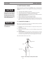
5.1 Flow Switch (Figure 5-1)
When excessive contamination is found in the air, the flow switch (FS) should be
removed, disassembled and cleaned as follows:
A.
B.
C.
D.
E.
Ensure the system is shut down and there is no trapped air under pressure in
the piping.
Remove the piston plug.
Remove the spring (FS-4 only). Use care when handling spring to prevent
distortion.
Remove the piston.
Clean all parts with cleaning agent. Ensure cleaning agent does not contain
solvents which can degrade polysulfone. Warm water and detergent is recommended for cleaning. Allow all parts to dry thoroughly before reassembly.
Reassemble the flow switch in reverse order.
PISTON PLUG
SPRING
PISTON
FLOW SWITCH
Figure 5-1. Disassembly / Assembly of Flow Switch
115
section 5
WARNING
ELECTRIC SHOCK CAN KILL! Be sure that all
primary power to the machine has been
externally disconnected. Open the line
(wall) disconnect switch or circuit breaker
before attempting inspection or work
inside of the power source.
WARNING
Voltages in plasma cutting equipment
are high enough to cause serious injury
or possibly death. Be particularly careful
around equipment when the covers are
removed.
MAINTENANCE
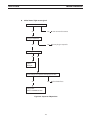
5.2 Troubleshooting
Check the problem against the symptoms in the following troubleshooting guide.
The remedy may be quite simple. If the cause cannot be quickly located, shut off
the input power, open up the unit, and perform a simple visual inspection of all the
components and wiring. Check for secure terminal connections, loose or burned
wiring or components, bulged or leaking capacitors, or any other sign of damage
or discoloration.
The cause of control malfunctions can be found by referring to the sequence of
operations (Figures 5-2 and 5-5) and electrical schematic diagram and checking the
various components. A volt-ohmmeter will be necessary for some of these checks.
NOTE
Before checking voltages in the circuit, disconnect the power from the high frequency
generator to avoid damaging your voltmeter.
116
section 5
MAINTENANCE
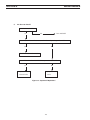
5.3 Troubleshooting Guide
A.
Difficult Starting.
• Change electrode
• Change nozzle
• Check for good, clean connection of work lead to workpiece
• Check air pressure (4.5-5.2 bar / 65-75 psig)
• Check torch power cable for continuity
Depress torch switch. After 2 seconds, is high frequency present?
Yes
No
Repair power
source
B.
No Air
Is air hose connected?
Yes
Repair/replace
high frequency
unit
No
Is air adjusted to 4.5-5.2 / 65-75 psig?
Yes
No
Does air come on with air check switch?
Yes
No
Check continuity of torch switch
Connect
OK
No
Repair power source
Figure 5-2. Sequence of Operations
117
Adjust
• No electrode in torch
• No valve pin in torch
• Replace electrode
• Replace valve pin
Replace torch switch
section 5
C.
MAINTENANCE
Air does not shut off
Is air check switch OFF?
Yes
No
Turn switch OFF
Does arc start when nozzle contacts work without depressing torch switch?
Yes
No
Check for short in torch switch
Does air flow even when POWERCUT 650 power switch is OFF?
Yes
Replace
solenoid valve
No
Repair power
source
Figure 5-3. Sequence of Operations
118
section 5
MAINTENANCE
D.
White "Power" light not energized.
Is main 230 volt switch ON?
No
Turn on main disconnect
No
Insert plug in receptacle
Is plug in receptacle?
Yes
Yes
Is cooling fan turning?
Yes
No
Replace
pilot light
Check voltage at receptacle and input power line
Yes
No
Check main fuses
Faulty power
switch on POWERCUT 650
Figure 5-4. Sequence of Operations
119
section 5
MAINTENANCE
E. Amber "FAULT" light ON.
Is the unit overheated?
("Fault" lights turns off
when Unit cools down.)
Yes
No
Is air flowing?
Duty cycle exceeded:
40% @ 40 A, 60% @ 30 A, Yes
or 100% @ 22 A output
See Sect 5.1
Is input voltage within ±15% of units input rating?
No
Yes
Adjust voltage •
No
Repair power source
Figure 5-5. Sequence of Operations
•
Fault light will energize if input voltage goes below or above ±15% of units
input rating. The light will not turn OFF even when correct voltage is restored.
Reset by placing POWERCUT 650 power switch OFF and then ON again.
NOTE: When in LOCK-IN mode, the FAULT light will turn on during second "trigger". This does not affect performance. Turn off.
120
section 5
MAINTENANCE
5.4 Sequence of Operation
A.LOCK-IN "OFF" position
RELEASE
PUSH
TORCH SWITCH
OPEN
CLOSE
GAS SOLENOID VALVE
2 SEC.
10 SEC
PREFLOW
FLOW SWITCH
Postflow
CLOSE
OPEN
FAULT PILOT LIGHT
ENERGIZE
HF CIRCUIT
INVERTER
CUTTING ARC (CURRENT)
NOTES:
1.
When the torch switch is pushed during postflow period, the postflow and preflow times are canceled, and the HF is
energized immediately.
2.
When the amber fault pilot light comes on, cutting operation should be stopped. The postflow time starts from the
moment the torch switch is released.
121
section 5
MAINTENANCE
B.LOCK-IN "ON" position
PUSH RELEASE
PUSH
RELEASE
TORCH SWITCH
OPEN
GAS SOLENOID VALVE
CLOSE
PREFLOW
2 SEC.
10 SEC
Postflow
OPEN
CLOSE
FLOW SWITCH
FAULT PILOT LIGHT
ENERGIZE
HF CIRCUIT
INVERTER
CUTTING ARC (CURRENT)
NOTES:
1.
When the torch switch is pushed during postflow period, the postflow and preflow times are canceled, and the HF is
energized immediately.
2.
When the amber fault pilot light comes on, cutting operation should be stopped. The postflow time starts from the
moment the torch switch is released.
3.
FAULT pilot light is on during second "turn-off" trigger only. This does not affect performance in any way.
122
section 5
MAINTENANCE
5.5Re-fitting the PT-31XLPC torch
1. For operator safety, the torch connections are located on the output terminal
board behind the lower portion of the front panel.
2. Thread the power cable and switch lead of the PT-31XLPC through the Strain
Relief on the Access Cover. Connect power cable to the torch fitting (left-hand
threads) and plug in the switch lead to the torch switch receptacle on the output
terminal board. Make sure the power cable connection is wrench-tight. Make
sure plug of switch lead is firmly locked in place.
3. Reassemble the access door to the power source. Retighten Strain Relief to secure
power cable, but do not overtighten.
ACCESS COVER FOR
TORCH CONNECTIONS
WORK CLAMP & CABLE
ASSEMBLY
STRAIN RELIEF
TORCH TRIGGER LEAD CON-TORCH POWER CABLE CONNECNECTION
TION
PT-31XLPC
Plasma Cutting
Torch
Figure 5-6. PT-31XLPC Torch Connections
123
section 5
MAINTENANCE
NOTE:
Schematics and Wiring Diagrams on 279.4mm x 431.8mm
(11” x 17”) paper are included inside the back cover of this
manual.
124