1
AR-B6002 Board
Fan-less with Intel ATOM Pineview + ICH8M
User Manual
1
Copyright 2013
All Rights Reserved.
Manual’s first edition:
For the purpose of improving reliability, design and function, the information in this
document is subject to change without prior notice and does not represent a commitment
on the part of the manufacturer.
The manufacturer (Acrosser) shall not be liable for direct, indirect, special, incidental,
or consequential damages arising out of the use or inability to use the product or
documentation, even if advised of the possibility of such damages.
This document contains proprietary information protected by copyright. All rights are
reserved. No part of this Manual may be reproduced by any mechanical, electronic, or other
means in any form without prior written permission of the manufacturer.
Trademarks
AR-B6002 is a registered trademarks of Acrosser; other product names mentioned
herein are used for identification purposes only and may be trademarks and/or registered
trademarks of their respective companies.
2
Table of Contents
1
INTRODUCTION ........................................................................ 5
1.1 Specifications ...................................................................................5
1.2 Package Contents ............................................................................6
1.3 Block Diagram ..................................................................................6
2
H/W INFORMATION .................................................................. 7
2.1
2.2
2.3
2.4
2.5
2.6
2.7
2.8
3
BIOS SETTING ........................................................................ 20
3.1
3.2
3.3
3.4
3.5
3.6
3.7
3.8
4
Main Setup .....................................................................................21
Advanced Setup .............................................................................23
Power Setup ...................................................................................25
PnP/PCI Setup ...............................................................................26
Peripherals Setup ...........................................................................28
PC Health Setup.............................................................................29
Boot Setup .....................................................................................30
Exit Setup .......................................................................................31
SOFTWARE INSTALLATION & PROGRAMMING GUIDE .... 33
4.1
4.2
4.3
4.4
5
Locations of Connector and Jumper Setting .....................................8
Connector and Jumper Setting Table..............................................10
Power Subsystem ..........................................................................15
Remote Switch ...............................................................................18
Status LED .....................................................................................18
Fuse selection ................................................................................19
COM1 / 2 to choose RS-232/RS-485/RS-422 by jumper setting.....19
GPIO ..............................................................................................19
Introduction ....................................................................................33
File Descriptions .............................................................................41
API List and Descriptions ...............................................................44
Appendix Programming Guide........................................................67
OPTIONAL MODULE INTRODUCTIONS ............................... 68
5.1 GPS Module ...................................................................................68
3
5.2
5.3
5.4
5.5
Bluetooth Module ...........................................................................68
WiFi Module ...................................................................................68
3.5G Module ...................................................................................69
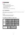
GPIO and CAN bus cable color ......................................................69
FAQ ................................................................................................ 70
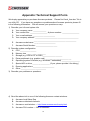
Appendix: Technical Support Form ............................................ 71
4
1
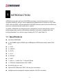
INTRODUCTION
AR-B6002 series with Intel Atom D425/D525 processor is a multi-functional In-Vehicle
computer suitable for using in various applications. Besides basic I/O ports like VGA, USB,
COM, LAN, and GPIO, and has embedded CAN BUS function to allow microcontrollers and
devices to communicate with each other in vehicle.
In addition, AR-B6002 has intelligent power management function with software utility to
monitor power status and to control power sequence, and is also compliant with most
industry standards for in-vehicle usage including CE, FCC, and E-Mark 13.
1.1 Specifications
Intel Atom D525/D425
1 x SO-DIMM supports DDRIII up to 4GB(Memory DDR3 data transfer rates of 800
MT/s)
1 x VGA
4 x USB2.0
2 x SATA
1 x CF II
4 x RS-232
1 x GbE
1 x Mic-In, 1 x Audio Out, 1 x Remote Switch
1 x CAN bus (Implementation ISO 11898)
8-bit GPIO with 4in / 4out
Optional WiFi/ Bluetooth/ GPS/ 3.5G solution for selection
Intelligent power management support standard 12V/24V car battery
5
1.2 Package Contents
Check if the following items are included in the package.
Quick Manual
AR-B6002
1 x Software Utility CD
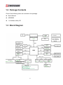
1.3 Block Diagram
6
2
H/W INFORMATION
This chapter describes the installation of AR-B6002. At first, it shows the Function diagram
and the layout of AR-B6002. It then describes the unpacking information which you should
read carefully, as well as the jumper/switch settings for the AR-B6002 configuration
7
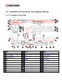
2.1 Locations of Connector and Jumper Setting
2.1.1 Locations (Top side)
CN6
CN18
PWR1
CN8
GPIO1
FUSE1
SATA_PWR1
CN5
CN23, CN24
SATA_PWR2
CN7
JP8, JP11
CN2
CN28
JP7, JP10
CN13
CN20
JP9, JP12
BH1
VGA1
U8
Minipcie1
SW1
CN21
Minipcie2
COM1 & COM2
DIMM1
CN17
COM3 & COM4
SATA1
LED1
AUDIO1
SATA2
8
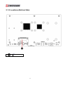
2.1.2 Locations (Bottom Side)
CF1
9
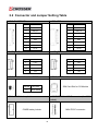
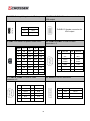
2.2 Connector and Jumper Setting Table
1. CN6: BLUETOOTH connector
2. CN8: GPS connector
PIN
DEFINE
PIN
DEFINE
1
GND
1
GND
2
USB_D+
2
USB_D+
3
USB_D-
3
USB_D-
4
+3.3V
4
+3.3V
5
LED
5
LED
6
BT_ON
6
GPS_ON
7
GND
7
GND
8
+3.3V
8
+3.3V
3. SATA_PWR1: SATA Power connector
4. SATA_PWR2: SATA Power connector
PIN
DEFINE
PIN
DEFINE
1
+12V
1
+12V
2
GND
2
GND
3
+3.3V
3
+3.3V
4
+5V
4
+5V
5. CN2: Pin Header for clear CMOS
STATUS
SETTING
1-2
Clear CMOS
6. CN13: SIM Card Slot
SIM Card Slot for 3G Module
7. BH1: CMOS battery holder
8. MINIPCIE1: Mini PCI-E connector. (for 3.5G
module)
CMOS battery holder
MINI PCI-E connector
10
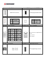
9. MINIPCIE2: Mini PCI-E connector
10. CN17: FPGA Programmable HEADER
FPGA programmable header
MINI PCI-E connector
11. LED1: Power State
12. CN18: CANBUS connector
LED
SIGNAL
G
PIC LED
G
HDD LED
Y
Power LED
PIN
13. GPIO1: GPIO connector
DEFINE
1
CAN_H
2
CAN_L
14. CN5: RJ45 + USB x 2 connector
PIN
DEFINE
PIN
DEFINE
1
GPO0
2
GPO1
3
GPO2
4
GPO3
5
GND
6
GND
7
GND
8
GND
9
GND
10
GND
11
GPI4
12
GPI5
13
GPI6
14
GPI7
15
N.C.
RJ45 connector for Gigabit Ethernet
port #1
Upper: Port #2
Lower: Port #1
15. CN7: USB connector
16. CN28: PIC Programming connector
Upper: Port #4
Lower: Port #3
PIC programming connector
11
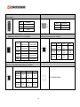
17. CN20: Setting Voltage level of Battery
STATUS
SETTING
1-2
+24V
2-3
+12V (Default)
18. VGA1: D-SUB-15 female connector for
VGA output
D-SUB-15 female connector for
VGA output
19. SW1: DIP switch for power mode select
20. COM1 & COM2: D-SUB-9P Male
connector × 2
Mode
1
2
3
4
0
ON
ON
ON
ON
1
ON
ON
ON
OFF
PIN
1
DEFINE
PIN
DCD
2
DEFINE
SIN
2
ON
ON
OFF
ON
3
ON
ON
OFF
OFF
4
ON
OFF
ON
ON
5
ON
OFF
ON
OFF
5
GND
6
DSR
6
ON
OFF
OFF
ON
7
RTS
8
CTS
7
ON
OFF
OFF
OFF
9
RI_12V
15
OFF
OFF
OFF
OFF
21. COM3 & COM4: D-SUB-9P Male
connector x 2
3
/DTSOUT
4
/422R+
/DT+
DTR
/422R-
22. AUDIO1: AUDIO connector
PIN
DEFINE
PIN
DEFINE
1
DCD
2
SIN
3
SOUT
4
DTR
5
GND
6
7
RTS
8
9
RI_12V
Color
SIGNAL
1
Pink
Mic-In
DSR
2
Green
Audio Out
CTS
3
Blue
Remote Switch
12
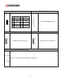
23. PWR1: Power Input Terminal Block
Connector
PIN
DEFINE
1
12V / 24V
2
IGN
3
GND
24. FUSE1: Fuse connector
25. CN23: RI SELECT for COM1/2
CN24: RI SELECT for COM3/4
STATUS
RI#
(Default)
+12V
RI#
(Default)
+12V
CN23
CN24
SETTING
SETTING
1, 2
Fuse Out
3, 4
Fuse In
STATUS
RS-232
JP7
1-2
1-2(COM1)
1-2(COM3)
(Default)
3-4(COM1)
3-4(COM3)
RS-422
3-4
RS-485
5-6
5-6(COM2)
7-8(COM2)
STATUS JP10
(Default)
DEFINE
27, 26, 28. JP7, JP8, JP9: RS-232 / RS-422 /
RS-485 Selection for COM1
5-6(COM4)
7-8(COM4)
27, 26, 28. JP10, JP11, JP12: RS-232 /
RS-422 / RS-485 Selection for COM2
RS-232
PIN
1-2
RS-422
3-4
RS-485
5-6
JP11
JP12
1-3
1-3
2-4
2-4
3-5
3-5
4-6
4-6
3-5
4-6
29. U8: SPI BIOS ROM
SPI BIOS ROM
N/A
13
JP8
JP9
1-3
1-3
2-4
2-4
3-5
3-5
4-6
4-6
3-5
4-6
N/A
30. CN21: BIOS Programmable Header
PIN
DEFINE
PIN
DEFINE
1
CS0
2
+3.3V
3
MISO
4
HOLD
5
WP
6
CLK
7
GND
8
MOSI
9
N.C.
10
N.C.
31. DIMM1: DDR-III SODIMM Socket
DDR-3 SODIMM Socket
32. SATA1: SATA device connector #1
33. SATA2: SATA device connector #2
SATA device connector #1
SATA device connector #2
34. CF1: Type-II compact flash card socket
+3.3V CF card only and UDMA mode supported
14
2.3 Power Subsystem
The AR-B6002 power subsystem converts the external DC input from vehicle to stable
power rails for internal mother board, peripherals, and external I/O. The power subsystem
can be configured by either an onboard switch SW1 or software to support various power
off delay time. There are 9 power modes available for your application.
2.3.1 Definition:
1.
Ignition: Ignition is a voltage input to command the power subsystem start a power on
and off cycle. It is treated as ON when voltage is above 1.1 Volts and OFF as voltage is
below 1.1 Volts. The maximum voltage input shall below 32 volts.
2.
Remote Switch: Remote switch input is an Open/Close latch switch. When you set the
power mode as 5, 6 or 7, it works with ignition to power on or off the system. It will be
treated as ON when the switch is CLOSED. It will be treated as OFF when the switch is
OPEN.
3.
Soft Off Delay: This is the delay time after ignition or remote switch is OFF till power
subsystem sends a turn off command to the motherboard. If ignition or remote switch is
turned ON again during this period, the power subsystem will cancel the OFF
procedure and back to operating condition.
4.
Hard Off Delay: This is the delay time after power subsystem detects the OS has been
shut down till the standby power is turned off.
2.3.2 Power Mode Description
Mode0: ATX function. System will be turned on and off by the remote switch. It
operates as standard PC power button.
Mode1: AT mode, Auto PWRBTN function. The power will be ON immediately
when external power present. The power will be OFF immediately when external
power is disconnected.
Mode2/3/4 (Ignition Only):
A. Power on is controlled by ignition (remote switch does not make any action to
power on).
B. Power subsystem sends “ON” command to motherboard when ignition is on for
more than 2 seconds.
C. Power subsystem will ignore the status change of ignition after ON command is
sent to motherboard for 3 minutes. After this period, the Power Module will start to
15
check its status. This can avoid an improper “OFF” process before the OS is
completely booted.
D. Power off is controlled by ignition. Remote switch does not make any action to
power off.
E. When Ignition is turn off, Power subsystem sends “OFF” pulse to motherboard
after Soft Off delay.
F. Power subsystem will ignore the status change of ignition during the “OFF”
command is sent out and OS is completely shut down. This will avoid an improper
ON process before the motherboard is completely shot off.
G. The system can be turned on again during Hard off delay period if the OFF
procedure already finished and the ignition is ON again.
Mode 5/6/7 (Ignition + remote Switch):
A. Power on is controlled by remote switch (ignition must be turned on before
pressing the remote switch).
B. Power subsystem sends “ON” command to motherboard when Remote switch is
on for more than 2 seconds.
C. Power subsystem will ignore the status change of ignition after ON command is
sent to motherboard for 3 minutes. After this period, the Power Module will start to
check its status. This can avoid an improper “OFF” process before the OS is
completely booted.
D. Power off is controlled by remote switch or ignition.
E. Power subsystem will ignore the status change of ignition and remote switch
during the “OFF” command is sent out and OS is completely shut down. This will
avoid an improper ON process before the motherboard is completely shot off.
F. The system can be turned on again if the OFF procedure already finished and
ignition or remote switch is ON again.
Mode 15: Software programmable mode. You can set the Soft Off Delay time,
Hard Off Delay time and Power ON source by software Application Program
Interface. Please refer to Chapter 4 for details.
Others modes are reserved for test only.
16
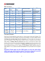
Mode description:
Mode
Soft OFF
Delay
Hard OFF
delay
Power ON Control
Power OFF
Control
0 (ATX)
No
No
By target board power
button
By target board
power button
1(AT)
No
No
DC on
DC off
2
5 seconds
1 minute
Ignition
Ignition
3
1 minute
5 minutes
Ignition
Ignition
4
30 minutes
2 hours
Ignition
Ignition
5
5 seconds
1 minute
Remote Switch
Ignition / Remote
(Ignition must be on first) Switch
6
1 minute
5 minutes
Remote Switch
Ignition / Remote
(Ignition must be on first) Switch
7
30 minutes
2 hours
Remote Switch
Ignition / Remote
(Ignition must be on first) Switch
15
(Software
control)
By user
setting
By user setting By user setting
Ignition / Remote
Switch
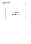
Low power protection:
Power input monitoring(before system boot on, during runtime, during soft off delay): The
Power smart function will constantly monitor the input voltage. If the input voltage is below
X Voltage (the standard might have 5% tolerance), the Smart Mode will not start the
power on procedure. When Power smart function has ran in operation and the battery
drops below Y Voltage (with 5% tolerance) more than 10 seconds the Power smart
function will shut down the motherboard following the standard shut down procedure. If the
input voltage recovers in 10 seconds over Y Voltage (with 5% tolerance) again, the Power
smart function will continue to run. (Figure 4) if this happens, ignition shall be off and on
again (Mode 2, 3, 4) or press the remote switch(Mode 5,6,7) if you want to turn on system
again.
Important: Please make sure the CN20 jumper is set to the right setting
which meet your vehicle power system. The power subsystem uses this
setting to identify the voltage of your vehicle power system.
17
STATUS
SETTING
1-2
+24V system
2-3
+12V system (Default).
For 12V car battery
For 24V car battery
X value
(Minimum Start up voltage)
11.2
23
Y value
(Auto shut down voltage)
10.8
22.5
2.4 Remote Switch
We provide a remote switch cable with latch switch. Use the remote switch cable can let
user turn on and turn off system easier.
2.5 Status LED
The LED will flash a number of blink to state the status.
Mode 0 and 1:
LED will be constant ON when power output is ON. LED will be constant OFF when power
output is off.
Mode 2 to 7 and mode 15(Smart ATX mode):
Each blink remains 500 milliseconds ON followed by a 500 ms OFF. Each Cycle will have a
5-second OFF in between.
Flashing Number
Status
0 (constant ON)
Power Output runs normally
1
Hard off mode
2
Standby mode (After power output is turned off until 5VSB is
turned off)
3
Power soft off delay. (After ignition is turned off or remote
switch is pressed until power output is turned off.)
4
Battery voltage low
5
System on/off fail. When motherboard cannot turn on or turn
off after retry.
18
Mode 8 / 9 / 10 / 11 / 12 / 13 / 14, which means no function in
current version.
6
6-128
Reserved
2.6 Fuse selection
AR-B6002 has external fuse holder, user can swap fuse according to the application. We
provide 7.5A fuse for 12V car battery, so that user’s cable should be able to endure 7.5A at
least.
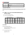
2.7 COM1 / 2 to choose RS-232/RS-485/RS-422 by
jumper setting
JP7, JP8, JP9 setting to COM1
JP10, JP11, JP12 setting to COM2
COM1 Type Selection
COM2 Type Selection
JP7
JP8
JP9
JP10
JP11
JP12
RS-232
1–2
1–3
2–4
1–3
2–4
RS-232
1–2
1–3
2–4
1–3
2–4
RS-422
3–4
3–5
4–6
3–5
4–6
RS-422
3–4
3–5
4–6
3–5
4–6
RS-485
5–6
3–5
4–6
N/A
RS-485
5–6
3–5
4–6
N/A
2.8 GPIO
GPO: Pin 1, Pin 2, Pin 3, Pin 4
Output voltage range: 5V~30V
Sink Current: Maximum 500mA each channel
Output Default set: Low
GPI: Pin 11, Pin 12, Pin 13, Pin 14
Logic High: 3V~32V
Logic Low: 0V~1.5V
19
3
BIOS SETTING
This chapter describes the BIOS menu displays and explains how to perform common
tasks needed to get the system up and running. It also gives detailed explanation of the
elements found in each of the BIOS menus. The following topics are covered:
Main Setup
Advanced Setup
Power Setup
PnP/PCI Setup
Peripherals Setup
PC Health Setup
Boot Setup
Exit Setup
Once you enter the Award BIOS™ CMOS Setup Utility, the Main Menu will appear on the
screen. Use the arrow keys to highlight the item and then use the <Pg Up> <Pg Dn> keys
to select the value you want in each item.
20
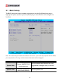
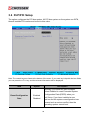
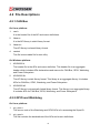
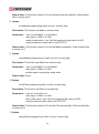
3.1 Main Setup
The BIOS setup main menu includes some options. Use the [Up/Down] arrow key to
highlight the option, and then press the [Enter] key to select the item and configure the
functions.
Note: The control keys are listed at the bottom of the menu. If you need any help with the item fields,
you can press the <F1> key, and the relevant information will be displayed.
Item
Option
Description
System Date
Format : MM/DD/YYYY
(month/day/year)
System Time
Format: HH:MM:SS
(hour:minute:second)
21
Set the system date. Note that the ‘Day’
automatically changes when you set the
date.
Set the system time.
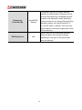
IDE Channel 0
Master/Slave
N/A
The onboard SATA Ports support user
connecting up to 2 SATA HDD.
The first SATA Port is the “IDE Channel 0
Master” and the second is “IDE Channel 1
Master”. BIOS will auto-detect the HDD
type.
Halt On
All Errors,
No Errors,
All but keyboard.
Select the situation in which you want the
BIOS to stop the POST process and notify
you.
22
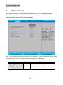
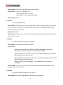
3.2 Advanced Setup
This section consists of configuration entries that allow you to improve your system
performance, or modify some system features according to your preference. Some entries
are required and reserved by the board’s design.
Note: The control keys are listed at the bottom of the menu. If you need any help with the item fields,
you can press the <F1> key, and the relevant information will be displayed.
Option
Choice
Hyper-Threading
Technology
Enabled
Disabled
Description
Enable for Windows XP and Linux
Disable for other OS.
23
Quick Power On Self
Test
Enabled
Disabled
This category speeds up the Power On
Self Test (POST) after you have powered
on the computer. If it is set to Enabled, the
BIOS will shorten or skip some check
items during POST.
Full Screen Logo Show
Enabled
Disabled
Select Enabled to show the full screen
logo if you have an add-in BIOS.
On-Chip Frame
Buffer Size
1Mb
8Mb
This Item is for setting the Frame Buffer
(Share system memory as display
memory).
DVMT mode
Enabled
Disabled
Total GFX Memory
This item sets the mode for dynamic video
memory technology
128MB
256MB
MAX
This item sets the mode for GFX video
memory
24
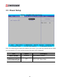
3.3 Power Setup
Note: The control keys are listed at the bottom of the menu. If you need any help with the item fields,
you can press the <F1> key, and the relevant information will be displayed.
Item
Option
ACPI Function
Enabled
ACPI Suspend Type
S3
S1
Description
ACPI System Support
ACPI S1/S3 Sleep State.
25
3.4 PnP/PCI Setup
The option configures the PCI bus system. All PCI bus system on the system use INT#,
thus all installed PCI cards must be set to this value.
Note: The control keys are listed at the bottom of the menu. If you need any help with the item fields,
you can press the <F1> key, and the relevant information will be displayed.
Item
Reset Configuration
Data
Option
Description
Normally, you leave this field Disabled.
Select Enabled to reset Extended System
Configuration Data (ESCD) when you
exit Setup. If you have installed a new
add-on and the system reconfiguration has
caused such a serious conflict, then the
operating system cannot boot.
Enabled
Disabled
26
Resources
Controlled By
IRQ Resources
The Award Plug and Play BIOS has the
capacity to automatically configure all of the
boot and Plug and Play compatible devices.
However, this capability means absolutely
nothing unless you are using a Plug and Play
operating system such as Windows 95. If
you set this field to “manual,” then you may
choose specific resources by going into each
of the submenus.
Auto(ESCD)
Manual
When resources are controlled manually,
assign a type to each system interrupt,
depending on the type of the device that
uses the interrupt
N/A
27
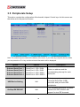
3.5 Peripherals Setup
This option controls the configuration of the board’s chipset. Control keys for this screen are
the same as for the previous screen.
Note: The control keys are listed at the bottom of the menu. If you need any help with the item fields,
you can press the <F1> key, and the relevant information will be displayed.
Option
Onboard Serial Port 1
Onboard Serial Port 2
Onboard Serial Port 3
Onboard Serial Port 4
USB Device Setting
OnChip IDE DEVICE
Choice
Serial Port 1: 3F8 / IRQ4
Serial Port 2: 2F8 / IRQ3
Serial Port 3: 3E8 / IRQ11
Serial Port 4: 2E8 / IRQ10
Description
Select an address and the
corresponding interrupt for each
serial port.
N/A
Select your system contains a
Universal Serial Bus (USB)
controller and you have USB
peripherals.
N/A
The integrated peripheral controller
contains an IDE interface with
support for two IDE channels.
28
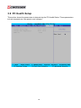
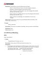
3.6 PC Health Setup
This section shows the parameters in determining the PC Health Status. These parameters
include temperatures, fan speeds, and voltages.
29
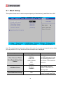
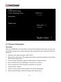
3.7 Boot Setup
This option allows user to select sequence/priority of boot device(s) and Boot from LAN.
Note: The control keys are listed at the bottom of the menu. If you need any help with the item fields,
you can press the <F1> key, and the relevant information will be displayed.
Option
Choice
Description
First / Second / Third
Boot Device/Other Boot
Device
Hard Disk
CDROM
USB-FDD
USB-CDROM
LAN
Disabled
The BIOS attempts to load
the operating system from
the devices in the selected
sequence.
LAN Boot Select
Enabled
Disabled
Hard Disk Boot Priority
N/A
30
These fields allow the
system to search for an
OS from LAN.
These fields set the Boot
Priority for each Hard Disk.
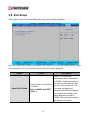
3.8 Exit Setup
This option is used to exit the BIOS main menu and change password.
Note: The control keys are listed at the bottom of the menu. If you need any help with the item fields,
you can press the <F1> key, and the relevant information will be displayed.
Option
Save & Exit Setup
Choice
Press <Enter> on this item
to confirm:
Save to CMOS and EXIT
(Y/N)? Y
31
Description
Press “Y” to store the
selections made in the menus
in CMOS – a special section of
the memory that stays on after
you turn your system off. The
next time you boot your
computer, the BIOS configures
your system according to the
setup selections stored in
CMOS. After saving the values,
the system will restart.
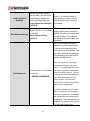
Load Optimized
Defaults
When you press <Enter>
on this item, you will see a
confirmation dialog box
with a message like this:
Load Optimized Defaults
(Y/N)? N
Exit Without Saving
Press <Enter> on this item
to confirm:
Quit without saving
(Y/N)? Y
Press ‘Y’ to load the default
values that are factory-set for
optimal-performance system
operations.
This allows you to exit Setup
without storing any changes in
CMOS. The previous selections
remain in effect. This will exit
the Setup utility and restart your
computer.
When a password has been
enabled, you will be prompted
to enter your password every
time you try to enter Setup. This
prevents unauthorized persons
from changing any part of your
system configuration.
Type the password, up to eight
characters in length, and press
<Enter>. The password typed now
Set Password
Press <Enter> on this item
to confirm:
ENTER PASSWORD:
will clear any previous password
from the CMOS memory. You will
be asked to confirm the password.
Type the password again and
press <Enter>. You may also
press <Esc> to abort the selection
and not enter a password.
To disable a password, just press
<Enter> when you are prompted
to enter the password. A message
will confirm that the password will
be disabled. Once the password is
disabled, the system will boot and
you can enter Setup freely.
32
4
SOFTWARE INSTALLATION &
PROGRAMMING GUIDE
4.1 Introduction
4.1.1 CAN bus
Overview
The CAN bus APIs provide interfaces to CAN bus subsystem. By invoking these APIs,
programmers can implement applications which have the functions listed below:
Set the BAUD rate.
Send the CAN packages over the CAN bus.
Receive the CAN packages via the CAN bus hardware interface.
Set receive mode to normal, STD only, EXTD only, or any.
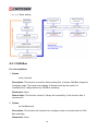
Set mask
Get mask
Set filter
Get filter
In this CAN bus API package, we provides:
1.
On Linux platform:
Linux driver module of CAN bus subsystem and the driver install / uninstall scripts.
On Windows platform:
We provide device driver and install program of CAN bus subsystem.
2.
API header file.
API libraries is static library format and shared library format.
3.
CAN bus test utility.
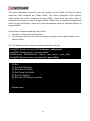
Installation Procedure of CAN Bus Driver
On Linux platform:
33
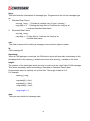
1. Change to the ‘root’ user account.
[Test@RD-System ~]$ su
Password:
<<< key in admin password
[root@RD-System Test]#
2. In the ‘driver’ directory, execute the script ‘install’.
[root@RD-System driver]# ./install
3. Make sure ‘arb6002’ is in the module list.
[root@RD-System driver]# lsmod
Module
Size
arb6002
85504
vfat
8744
Used by
0
1
4. If the driver is no longer needed, execute the script ‘uninstall’ to unload the driver.
[root@RD-System
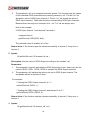
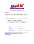
On Windows platform:
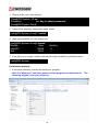
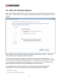
1. In the driver directory, execute the ‘setup.exe’ program.
Note: For Windows 7 and Vista, please run this program as administration.
following diagram is for your reference.
34
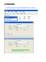
The
The following diagram is copied for Windows XP for your reference.
35
The CAN bus APIs
Before executing the applications which invoke the CAN bus APIs, users should make sure
that the Linux device driver or the Windows device driver of CAN bus has been installed.
On Linux platform, after successfully installing the device driver, a character device node
named “/dev/can0” will be created automatically. The APIs open the device node
“/dev/can0” implicitly so acquiring a file descriptor of “/dev/can0” by users is not necessary.
In order not to degrade the performance of the CAN bus subsystem, the device node
“/dev/can0” is limited to be opened at most once at any moment, i.e., if application A
accesses CAN bus via the APIs, the application B which either tries to open ‘/dev/can0’ or
uses CAN bus API will result in failure.
On Windows platform, after successfully installing the device driver, there is a device which
shows ‘CAN Bus Driver’ in the ‘Device Manager’. The APIs on Windows platform open this
device implicitly. User can call the APIs directly without opening the CAN Bus subsystem
device.
CAN Message Format
// TPE DEFINE
typedef char
typedef unsigned char
typedef short
typedef unsigned short
typedef unsigned long
typedef int
typedef
i8;
u8;
i16;
u16;
u32;
i32;
struct {
i32
i32
u32
struct timeval
i16
u8
} canmsg_t;
flags;
cob;
id;
timestamp;
length;
data[8];
To transmit a CAN package, the programmer has to fill in the fields in the variable of type
canmsg_t and pass this canmsg_t variable as an argument to invoke the APIs. The fields in
CAN message are described below:
36
flags:
This field holds the information of message type. Programmers can set the message type
as:
1. Standard Data Frame:
canmsg_t msg; // Declare a variable ‘msg’ of type ‘canmsg_t’
msg.flags = 0; // Setting the flags field to 0 defines the ‘msg’ as an
// ordinary standard data frame.
2. Extended Data Frame:
canmsg_t msg;
msg.flags = 1 // flags field to 1 defines the ‘msg’ as an
//extend data frame.
cob:
This field is reserved for holding a message communication object number.
id:
CAN message ID.
timestamp:
When a CAN package is received, the CAN device driver will annotate a timestamp to the
timestamp field in the canmsg_t variable and return this canmsg_t variable to the caller.
length:
The number of the data bytes which are sent or received in the ‘data’ field of CAN message.
This field is necessary while transmitting a Standard or Extended Data Frame.
Programmers have to explicitly set up this field. The length of data is 0~8.
For example:
canmsg_t msg;
msg.data[0] = 0xa1;
msg.data[1] = 0xb2;
msg.data[2] = 0xc3;
msg.length = 3;
data:
The byte array holds the message data.
37
4.1.2 GPIO and Watchdog
Overview
AR-B6002 provides both a GPIO interface and a Watchdog timer. Users can use the GPIO
and Watchdog APIs to configure and to access the GPIO interface and the Watchdog timer.
The GPIO has four input pins and four output pins. The Watchdog timer can be set to
1~255 seconds. Setting the timer to zero disables the timer. The remaining seconds of the
timer to reboot can be read from the timer.
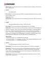
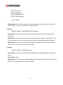
In this GPIO and Watchdog package, on Linux and Windows platform, we provide:
GPIO and Watchdog test utility.
P.S. The following is Windows reference pictures about the utility file:
P.S. The following is Linux reference pictures about the utility file:
[root@RD-System ap_and_lib]# cd gpio_watchdog
[root@RD-System gpio_watchdog]# ls
libSioAcce.a libSioAcce.so main.c sio_acce.h sio_utility
[root@RD-System gpio_watchdog]# ./sio_utility
38
(0) Exit
(1) Set GPIO Output.
(2) Set Watchdog Timer.
GPIO IN f
1111
Information:
Please input:
GPIO OUT 0
0000
Watchdog Counter
0000 0000
0
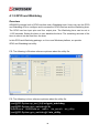
4.1.3 Power Subsystem
Overview
When the AR-B6002 is at Power Mode 15, the Power Subsystem APIs can be used to get
and set the configuration of power subsystem. By invoking the Power Subsystem APIs, the
users can:
1.
Get the current status of ignition (ON or OFF).
2.
Set the Power-On mode. This setting will be kept in the power subsystem and will take
effect at next system boot.
3.
From the power subsystem, get the stored setting of Power-On mode.
4.
Get or set the time of Hard Off delay in seconds or in minutes.
5.
Get or set the time of Soft Off delay in seconds or in minutes
6.
Get the battery voltage.
7.
Get the version number of the firmware of the Power Subsystem.
8.
Set the Hard Off delay and Soft Off delay to the default value.
39
The power subsystem connects to the main system via the COM6. The Linux’s default
supported COM interfaces are COM1~COM4. The Power Subsystem APIs implicitly
communicate with power subsystem through COM6. Users must take extra steps to
configure Linux kernel in order to support COM6. Please refer to Appendix Programming
Guide for more information. Users don’t need extraordinary setup on Windows platform to
support COM6.
In this Power Subsystem package, we provide:
1.
2.
The APIs to access power subsystem.
The utility and source code to monitor and set up power modes, ignition status, and
power-off time.
P.S. The following is Linux reference pictures about the utility file:
[root@RD-System ap_and_lib]# cd power_subsystem/
[root@RD-System power_subsystem]# ls
libPwrAcce.a libPwrAcce.so main.c pwr_acce.h pwr_utility
[root@RD-System power_subsystem]# ./pwr_utility
(0) Exit
(1) Set Soft Off Delay.
(2) Set Hard Off Delay.
(3) Set Power On Mode.
(4) Set PIC Default.
(5) Set Soft Off Dealy in minutes.
Please input:
40
4.2 File Descriptions
4.2.1 CAN Bus
On Linux platform:
1.
can.h
It is the header file of the API and macro definitions.
2.
libcan.a
It is the API library in static library format.
3.
libcan.so
The API library is shared library format.
4.
cantest
The file is executable file for test utility.
On Windows platform:
1.
AR-B6002.h
The header file is the APIs and macro definition. This header file is an aggregate
header which includes APIs declarations and macros for CAN Bus, GPIO, Watchdog,
and Power Subsystem.
2.
AR-B6002.lib
The API library is static library format. This library is an aggregate library. It includes
APIs for CAN Bus, GPIO, Watchdog, and Power Subsystem.
3.
AR-B6002.dll
The API library is dynamically linked library format. This library is an aggregate library.
It includes APIs for CAN Bus, GPIO, Watchdog, and Power Subsystem.
4.2.2 GPIO and Watchdog
On Linux platform:
1.
sio_acce.c
The source code of the Watchdog and GPIO APIs is for accessing the SuperIO.
2.
sio_acce.h
This file includes the declarations of the APIs and macro definitions.
41
3.
main.c
It is the source code of the utility.
4.
Makefile
On Windows platform:
1.
AR-B6002.h
The header file is the APIs and macro definition. This header file is an aggregate
header which includes APIs declarations and macros for CAN Bus, GPIO, Watchdog,
and Power Subsystem.
2.
AR-B6002.lib
The API library is static library format. This library is an aggregate library. It includes
APIs for CAN Bus, GPIO, Watchdog, and Power Subsystem.
3.
AR-B6002.dll
The API library is dynamically linked library format. This library is an aggregate library.
It includes APIs for CAN Bus, GPIO, Watchdog, and Power Subsystem.
4.2.3 Power Subsystem
On Linux platform:
1.
pwr_acce.c
The source code of the APIs is for accessing the power subsystem.
2.
pwr_acce.h
This file includes the declarations of the APIs and macro definitions.
3.
main.c
It is the source code of the utility.
4.
Makefile
On Windows platform:
1.
AR-B6002.h
The header file is the APIs and macro definition. This header file is an aggregate
header which includes APIs declarations and macros for CAN Bus, GPIO, Watchdog,
and Power Subsystem.
42
2.
AR-B6002.lib
The API library is static library format. This library is an aggregate library. It includes
APIs for CAN Bus, GPIO, Watchdog, and Power Subsystem.
3.
AR-B6002.dll
The API library is dynamically linked library format. This library is an aggregate library.
It includes APIs for CAN Bus, GPIO, Watchdog, and Power Subsystem.
43
4.3 API List and Descriptions
Note: For programming under Windows 7 and Vista environment, please take care about Microsoft
UAC policy.
Or else, user must to change UAC setting from "Default" to "Never Notify" to run the
program.
Note: CAN Bus must be initialized before activation by syntax lib_init(void).
“normal mode” and “configure mode” for CAN bus.
There are
The normal mode can be entered from configure mode by syntax CanStart(void). The
normal mode is the standard operating mode. In this mode, the device actively monitors all
bus messages and generates acknowledge bits, error frames, etc. This is also the only
mode in which the function will transmit messages over the CAN bus.
The configure mode can be entered from normal mode by syntax CanStop(void).
Configure mode is the only mode where the following functions are available:
‧ Ba ud Ra te s e tting
‧ Filte r S e tting a nd Ma s k S e tting
44
‧ Re ce ive Mode setting
4.3.1 CAN Bus
For Linux platform:
1. Syntax:
int lib_init(void)
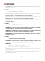
Description: This function is used for library calling first. It causes CAN Bus chipset at
Configure mode. The mode must change to Normal mode by the syntax "int
CanStart(void)" calling before any CAN Bus operating.
Parameters: None.
Return Value: This function returns 0, library init successfully. If this function fails, it
returns not 0.
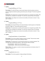
2. Syntax:
int CanStart(void)
Description: This function will resume from configure mode to normal mode for CAN
Bus operating..
Parameters: None.
45
Return Value: This function returns 0 if it set the Baud rate successfully. If this function
fails, it returns not 0.
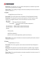
3. Syntax:
int CanStop(void)
Description: This function will stop CAN Bus message sending and receiving, as well
as into configure mode.
Parameters: None.
Return Value: This function returns 0 if it successfully. If this function fails, it returns not
0.
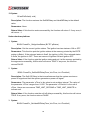
4. Syntax:
void sendCanMessages( canmsg_t* buffer, u8 count)
Description: This function sends out CAN packages over the CAN bus.
Parameters: If there is more than one CAN package to send, these CAN packages are
stored in a ‘canmsg_t’ array. This function sends out packages in a sequential fashion.
The memory address of the first CAN package to send is pointed at the parameter
‘buffer’. The number of CAN packages to send is indicated by the parameter ‘count’. If
the resource of sending out the CAN package is temporarily unavailable, the process
will be temporarily halted (Block I/O) until the resource is available again.
Return Value:
This function returns “0” if message sent successfully.
This function returns “-1” if message sent failure. This message is abandoned to send.
This function returns “-2” if CAN bus linking failed.
5. Syntax:
int getCanMessages( canmsg_t* buffer, u8 count)
Description: This function receives CAN packages from the CAN bus subsystem.
Parameters: This function stores received CAN packages sequentially at an array of
type ‘canmsg_t’. The number of packages to receive is indicated by the parameter
‘count’. Before receiving finished, the process will be temporarily halted (Block I/O) if
there is no incoming CAN package.
Return Value: If this function receives the packages successfully, it returns 0. If this
function fails, it returns not 0.
46
6. Syntax:
int CanSetBaudRate(unsigned long Baud)
Description: This function sets up the speed ( Baud rate ) of sending and receiving
CAN packages.
Parameters: The parameter ‘Baud’ could be: ( the unit is Kbps )
10 , 20 , 50 , 100 , 125 , 250 , 500 , 800 , 1000
The default speed is 0 Kbps.
Return Value: This function returns 0 if it set the Baud rate successfully. If this function
fails, it returns not 0.
7. Syntax:
int CanGetBauRate(unsigned long *Baud)
Description: This function get the speed ( Baud rate ) of sending and receiving CAN
packages.
Parameters: The parameter pointer ‘Baud’ record: ( the unit is Kbps )
10, 20, 50, 100, 125, 250, 500, 800, 1000
Return Value: This function returns 0 if it set the Baud rate successfully. If this function
fails, it returns not 0.
8. Syntax:
int setMask(unsigned long mask, int num, int extd_flag)
Description: This function setMask to can bus chip.
Parameters: num 0 is set Mask0, 1 is set Mask1.
extd_flag 1 is 29bit, 0 is 11bit
mask is mask value, if set 11bit the maximum mask value is 0x7ff,
else the maximum mask value is 0x1FFFFFFF
Return Value: This function returns 0 if it set the Mask successfully. If this function fails,
it returns not 0.
9. Syntax:
void getMask(unsigned long *mask, int num, int extd_flag)
Description: This function get Mask from can bus chip.
Parameters: num 0 is get Mask0, 1 is get Mask1.
47
extd_flag 1 is 29bit, 0 is 11bit
pointer mask is recored get mask value.
Return Value: None.
10. Syntax:
int setFilter(unsigned long filter, int num, int extd_flag)
Description: This function set Filter to can bus chip.
Parameters: num 0~5 is set filter 0~5.
extd_flag 1 is 29bit, 0 is 11bit
filter is filter value, if set 11bit the maximum filter value is 0x7ff,
else the maximum filter value is 0x1FFFFFFF
Return Value: This function returns 0 if it set the Filter successfully. If this function fails,
it returns not 0.
11. Syntax:
void getFilter(unsigned long *filter, int num, int extd_flag)
Description: This function get Filter from can bus chip.
Parameters: num 0~5 is get filter 0~5.
extd_flag 1 is 29bit, 0 is 11bit
pointer filter is recored get filter value
Return Value: None.
12. Syntax:
int CanChipReSet(void)
Description: This function to reset can bus chip. It causes CAN Bus chipset at
Configure mode. The mode must change to Normal mode by the syntax "int
CanStart(void)" calling before any CAN Bus operating.
Parameters: None.
Return Value: This function returns 0 if it reset the chipset successfully. If this function
fails, it returns not 0.
13. Syntax:
int setReciveMode(unsigned long Mode)
48
Description: This function set Receive Mode.
Parameters:
Mode 0 is Normal Receive, Receive all valid messages using either
standard or extended identifiers that meet filter criteria.
Mode 1 is Receive only STD , Receive only valid messages with
standard identifiers that meet filter criteria
Mode 2 is Receive only EXTD , Receive only valid messages with
extended identifiers that meet filter criteria
Mode 3 is Receive any Message , Turn mask/filters off; receive any
message
Return Value: This function returns 0 if it set the Receive Mode successfully. If this
function fails, it returns not 0.
14. Syntax:
int getReciveMode(unsigned long *Mode)
Description: This function get Receive Mode from can chipset.
Parameters: pointer Mode to record the Mode from can chipset.
Mode 0 is Normal Receive, Receive all valid messages using either
standard or extended identifiers that meet filter criteria.
Mode 1 is Receive only STD , Receive only valid messages with
standard identifiers that meet filter criteria
Mode 2 is Receive only EXTD , Receive only valid messages with
extended identifiers that meet filter criteria
Mode 3 is Receive any Message , Turn mask/filters off; receive any
message
Return Value: This function returns 0 if it get the Receive Mode successfully. If this
function fails, it returns not 0.
15. Syntax:
void lib_close(void)
Description: This function is invoked to close library, when you doesn’t use this library.
Parameters: None.
49
Return Value: None.
For Windows platform:
1. Syntax:
int lib_init(void)
Description: This function is used for library calling first. It causes CAN Bus chipset at
Configure mode. The mode must change to Normal mode by the syntax "int
CanStart(void)" calling before any CAN Bus operating.
Parameters: None.
Return Value: This function returns 0, library init successfully. If this function fails, it
returns not 0.
2. Syntax:
int CanStart(void)
Description: This function will resume from configure mode to normal mode for CAN Bus
operating..
Parameters: None.
Return Value: This function returns 0 if it set the Baud rate successfully. If this function
fails, it returns not 0.
3. Syntax:
int CanStop(void)
Description: This function will stop CAN Bus message sending and receiving, as well
as into configure mode.
Parameters: None.
Return Value: This function returns 0 if it successfully. If this function fails, it returns not
0.
4. Syntax:
void sendCanMessages( canmsg_t* buffer, u8 count)
Description: This function sends out CAN packages over the CAN bus.
Parameters: If there is more than one CAN package to send, these CAN packages are
50
stored in a ‘canmsg_t’ array. This function sends out packages in a sequential fashion.
The memory address of the first CAN package to send is pointed at by the parameter
‘buffer’. The number of CAN packages to send is indicated by the parameter ‘count’. If
the resource of sending out the CAN package is temporarily unavailable, the process
will be temporarily halted (Block I/O) until the resource is available again.
Return Value: None.
5. Syntax:
int getCanMessages( canmsg_t* buffer, u8 count)
Description: This function receives CAN packages from the CAN bus subsystem.
Parameters: This function stores received CAN packages sequentially at an array of
type ‘canmsg_t’. The number of packages to receive is indicated by the parameter
‘count’. Before receiving finished, the process will be temporarily halted (Block I/O) if
there is no incoming CAN package.
Return Value: If this function receives the packages successfully, it returns 0. If this
function fails, it returns not 0.
6. Syntax:
int CanSetBaudRate(unsigned long Baud)
Description: This function sets up the speed ( Baud rate ) of sending and receiving
CAN packages.
Parameters: The parameter ‘Baud’ could be: ( the unit is Kbps )
10, 20, 50, 100, 125, 250, 500, 800, 1000
The default speed is 0 Kbps.
Return Value: This function returns 0 if it set the Baud rate successfully. If this function
fails, it returns not 0.
7. Syntax:
int CanGetBauRate(unsigned long *Baud)
Description: This function get the speed ( Baud rate ) of sending and receiving CAN
packages.
Parameters: The parameter pointer ‘Baud’ record: (the unit is Kbps)
10, 20, 50, 100, 125, 250, 500, 800, 1000
51
Return Value: This function returns 0 if it set the Baud rate successfully. If this function
fails, it returns not 0.
8. Syntax:
int setMask(unsigned long mask, int num, int extd_flag)
Description: This function set Mask to can bus chip.
Parameters: num 0 is set Mask0, 1 is set Mask1.
extd_flag 1 is 29bit, 0 is 11bit
mask is mask value, if set 11bit the maximum mask value is 0x7ff,
else the maximum mask value is 0x1FFFFFFF
Return Value: This function returns 0 if it set the Mask successfully. If this function fails,
it returns not 0.
9. Syntax:
void getMask(unsigned long *mask, int num, int extd_flag)
Description: This function get Mask from can bus chip.
Parameters: num 0 is get Mask0, 1 is get Mask1.
extd_flag 1 is 29bit, 0 is 11bit
pointer mask is recored get mask value.
Return Value: None.
10. Syntax:
int setFilter(unsigned long filter, int num, int extd_flag)
Description: This function set Filter to can bus chip.
Parameters: num 0~5 is set filter 0~5.
extd_flag 1 is 29bit, 0 is 11bit
filter is filter value, if set 11bit the maximum filter value is 0x7ff,
else the maximum filter value is 0x1FFFFFFF
Return Value: This function returns 0 if it set the Filter successfully. If this function fails,
it returns not 0.
11. Syntax:
void getFilter(unsigned long *filter, int num, int extd_flag)
52
Description: This function get Filter from can bus chip.
Parameters: num 0~5 is get filter 0~5.
extd_flag 1 is 29bit, 0 is 11bit
pointer filter is recored get filter value
Return Value: None.
12. Syntax:
int CanChipReSet(void)
Description: This function to reset can bus chip. It causes CAN Bus chipset at Configure
mode. The mode must change to Normal mode by the syntax "int CanStart(void)" calling
before any CAN Bus operating.
Parameters: None.
Return Value: This function returns 0 if it reset the chipset successfully. If this function
fails, it returns not 0.
13. Syntax:
int setReciveMode(unsigned long Mode)
Description: This function set Receive Mode.
Parameters:
Mode 0 is Normal Receive, Receive all valid messages using either
standard or extended identifiers that meet filter criteria.
Mode 1 is Receive only STD , Receive only valid messages with standard
identifiers that meet filter criteria
Mode 2 is Receive only EXTD , Receive only valid messages with extended
identifiers that meet filter criteria
Mode 3 is Receive any Message , Turn mask/filters off; receive any
message
Return Value: This function returns 0 if it set the Receive Mode successfully. If this
function fails, it returns not 0.
14. Syntax:
int getReciveMode(unsigned long *Mode)
Description: This function get Receive Mode from can chipset.
53
Parameters: pointer Mode to record the Mode from can chipset.
Mode 0 is Normal Receive, Receive all valid messages using either
standard or extended identifiers that meet filter criteria.
Mode 1 is Receive only STD, Receive only valid messages with standard
identifiers that meet filter criteria
Mode 2 is Receive only EXTD, Receive only valid messages with extended
identifiers that meet filter criteria
Mode 3 is Receive any Message, Turn mask/filters off; receive any
message
Return Value: This function returns 0 if it get the Receive Mode successfully. If this
function fails, it returns not 0.
15. Syntax:
void lib_close(void)
Description: This function is invoked to close library, when you doesn’t use this library.
Parameters: None.
Return Value: None.
4.3.2 GPIO and Watchdog
GPIO
Under Linux platform:
1. Syntax:
i32 getInChLevel( i32 channel, u8 *val )
Description: Get the value of GPIO Input and put the value at *val.
Parameters:
I. The parameter ‘channel’ indicates the GPIO Input pins to show. Users can use the
macros GPI0, GPI1, GPI2, GPI3 to indicate the GPIO Input channel. For example:
getInChLevel( GPI2, &val); // Indicate the GPIO Input channel 2
getInChLevel( GPI0 | GPI3, &val); // Indicate the GPIO Input
// channel 0 and channel 3
54
II.
The parameter ‘val’ is an unsigned character pointer. The function puts the values
of the indicated GPIO channels at the memory pointed by ‘val’. The bit 0 of *val
shows the value of GPIO Input channel 0. The bit 1 of *val shows the value of
GPIO Input channel 1. Other bits show the corresponding GPIO Input channels.
Because there are only four channels, bit 4 ~ bit 7 of *val are always zero.
Here is an example:
If GPIO Input channel 1 and channel 3 are both 1.
unsigned char ch;
getInChLevel( GPI1|GPI3, &ch );
The returned value of variable ‘ch’ is 0xa.
Return Value: If the function gets the values successfully, it returns 0. If any error, it
returns –1.
2. Syntax:
i32 setOutChLevel( i32 channel, u8 val )
Description: Set the value of GPIO Output according to the variable ‘val’.
Parameters:
I. The parameter ‘channel’ indicates the GPIO Output pins to set. Users can use the
macros GPO0, GPO1, GPO2, GPO3 to indicate the GPIO Output channels.
II. The parameter ‘val’ indicate the value to be set to GPIO Output channel. The
acceptable values is limited to 0 and 1.
For example:
/* Setting the GPIO Output channel 2 to 1 */
setOutChLevel( GPO2, 1 );
/* Setting the GPIO Output channel 0 and channel 3 to 0 */
getInChLevel( GPO0 | GPO3, 0 );
Return Value: If the function sets the values successfully, it returns 0. If any error, it
returns –1.
3. Syntax:
i32 getOutchLevel( i32 channel, u8 *val )
55
Description: Get the value of GPIO Output and put the value at *val.
Parameters:
I. The parameter ‘channel’ indicates the GPIO Output pins to show. Users can use
the macros GPO0, GPO1, GPO2, GPO3 to indicate the GPIO Output channel. For
example:
getOutChLevel( GPO2, &val); // Indicate the GPIO Output channel 2
/* Indicate the GPIO Output channel 0 and channel 3. */
getOutChLevel( GPO0 | GPO3, &val);
II.
The parameter ‘val’ is an unsigned character pointer. The function puts the values
of the indicated GPIO channels at the memory pointed by ‘val’. The bit 0 of *val
shows the value of GPIO Output channel 0. The bit 1 of *val shows the value of
GPIO Output channel 1. Other bits show the corresponding GPIO Output
channels. Because there are only four channels, bit 4 ~ bit 7 of *val are always
zero.
Here is an example:
If GPIO Output channel 0 and channel 2 are both 1.
unsigned char ch;
getOutChLevel( GPO0|GPO2, &ch );
The returned value of variable ‘ch’ is 0x5.
Return Value: If the function gets the values successfully, it returns 0. If any error, it
returns –1.
Under windows platform:
1. Syntax:
int getGPIOBitValue(int iBitNumber, bool * bValue)
Description: Get the value of GPIO and put the value at * bValue.
Parameters:
I. The parameter ‘iBitNumber indicates the GPIO Input pins to show. Users can use
the macros GPO_BIT_0, GPO_BIT_1, GPO_BIT_2, GPO_BIT_3, GPI_BIT_4,
GPI_BIT_5, GPI_BIT_6, or GPI_BIT_7 to indicate the GPIO channel. For
56
example:
getGPIOBitValue (GPO_BIT_0, &val);
// Indicate the GPIO Output channel 0
getGPIOBitValue (GPI_BIT_6, &val);
// Indicate the GPIO Input channel 6
II.
The parameter ‘bValue’ is an bool pointer. The function puts the values of the
indicated GPIO channels at the memory pointed by ‘bValue’. True indicates HI,
and false indicates LOW.
Return Value: If the function gets the values successfully, it returns 0. If any error, it
returns not zero.
2. Syntax:
int setGPIOBitValue(int iBitNumber, bool bValue)
Description: Set the value of GPIO Output according to the variable ‘bValue’.
Parameters:
I. The parameter ‘channel’ indicates the GPIO Output pins to set. Users can use the
macros GPO_BIT_0, GPO_BIT_1, GPO_BIT_2, or GPO_BIT_3 to indicate the
GPIO Output channels.
II. The parameter ‘bValue’ indicate the value to be set to GPIO Output channel. True
indicates HI, and false indicates LOW.
For example:
/* Setting the GPIO Output channel 2 to HI */
setGPIOBitValue (GPO_BIT_2, true );
/* Setting the GPIO Output channel 3 to LOW */
setGPIOBitValue (GPO_BIT_3, false );
Return Value: If the function sets the values successfully, it returns 0. If any error, it
returns not zero.
Watchdog
Under Linux platform:
1. Syntax:
u8 getWtdTimer(void)
57
Description: This function read the value of the watchdog time counter and return it to
the caller.
Parameters: None.
Return Value: This function return the value of the time counter and return it to the
caller as an unsigned integer.
2. Syntax:
void setWtdTimer( u8 val )
Description: This function sets the watchdog timer register to the value ‘val’ and starts
to count down. The value could be 0 ~ 255. The unit is second. Setting the timer register
to 0 disables the watchdog function and stops the countdown.
Parameters: The parameter ‘val’ is the value to set to watchdog timer register. The
range is 0 ~ 255.
Return Value: None.
Under windows platform:
1. Syntax:
int readWatchdog(unsigned char * pucValue)
Description: This function read the value of the watchdog time counter and return it to
the caller.
Parameters: The parameter ‘pucValue’ is an unsigned character pointer. The function
puts the values read from watchdog at the memory pointed by ‘pucValue’.
Return Value: If the function gets the values successfully, it returns 0. If any error, it
returns not zero.
2. Syntax:
int startWatchdog(unsigned char ucUnit, unsigned char ucValue)
Description: This function sets the watchdog timer register to the value ‘ucValue’ and
starts to count down. The value could be 0 ~ 255. The unit is second. Setting the timer
register to 0 disables the watchdog function and stops the countdown.
Parameters: The parameter ‘ucUnit’ is the unit to set to watchdog timer register. ‘0’
indicates second. And ‘1’ indicates minute. The parameter ‘ucValue’ is the value to set to
watchdog timer register. The range is 0 ~ 255.
58
Return Value: If the function gets the values successfully, it returns 0. If any error, it
returns not zero.
4.3.3 Power Subsystem
Under Linux platform:
1. Syntax:
i32 getIgnStatus( u8 *ignStatus )
Description: Get the current ignition status. The ignition has two statuses: ON or OFF.
Parameters: This function puts the ignition status at the memory pointed by the
unsigned character pointer ‘ignStatus’. If the returned status is 0xa5, the ignition is ON.
If the returned status is 0x5a, the ignition is OFF. There are macros of Ignition ON and
Ignition OFF in pwr_acce.h.
Return Value: If the function gets the ignition status and put it at the memory pointed by
the argument successfully, this function will return 0. If any error, the function returns –1.
2. Syntax:
i32 setSoftOffDelayS( u32 setTime )
Description: The Soft Off Delay is the interval between that the system receives a
power off signal and that the system generates a power off signal. This function sets up
the interval in seconds.
Parameters: The parameter is of the type of unsigned long. The value of the parameter
ranges from 0~255. The unit of the value of the parameter is seconds.
Return Value: If the function sets the delay time successfully, it will return 0. If any error,
the function returns –1.
3. Syntax:
i32 setSoftOffDelayM( u32 setTime )
Description: The Soft Off Delay is the interval between that the system receives a
power off signal and that the system generates a power off signal. This function sets up
the interval in minutes.
Parameters: The parameter is of the type of unsigned long. The value of the parameter
ranges from 0~255. The unit of the value of the parameter is minutes.
59
Return Value: If the function sets the delay time successfully, it will return 0. If any error,
the function returns –1.
4. Syntax:
i32 setHardOffDelayS( u32 setTime )
Description: The Hard Off Delay is the interval between that the system is off and that
the power 5VSB is off. This functions set up the interval in seconds.
Parameters: The parameter is of the type of unsigned long. The value of the parameter
ranges from 0~255. The unit of the value of the parameter is seconds.
Return Value: If the function sets the delay time successfully, it will return 0. If any error,
the function returns –1.
5. Syntax:
i32 setHardOffDelayM( u32 setTime )
Description: The Hard Off Delay is the interval between that the system is off and that
the power 5VSB is off. This functions set up the interval in minutes.
Parameters: The parameter is of the type of unsigned long. The value of the parameter
ranges from 0~255. The unit of the value of the parameter is minutes.
Return Value: If the function sets the delay time successfully, it will return 0. If any error,
the function returns –1.
6. Syntax:
i32 setPowerOnMode( u8 powerOnMode )
Description: The function sets up the source of the boot-up signal of the system. There
are two choices: boot from the Ignition or boot from the Remote Switch.
Parameters:
PowerOnMode = 0xa5, boot up by the Ignition.
PowerOnMode = 0x5a, boot up by the Remote Switch.
There are macros of Ignition mode and Remote Switch mode in pwr_acce.h (Linux) and
AR-B6002.h(Windows).
Return Value: If the function sets power-on mode successfully, it will return 0. If any
error, the function returns –1.
60
7. Syntax:
i32 getSoftOffDelay( u32 *Time )
Description: The Soft Off Delay is the interval between that the system receives a
power off signal and that the system generates a power off signal. This function gets the
interval.
Parameters: The parameter is a pointer which points to an unsigned long variable. The
returned value is stored at this variable. The unit of the returned value is in seconds.
Return Value: If the delay time is returned successfully, the function returns 0. If any
error, it returns –1.
8. Syntax:
i32 getHardOffDelay( u32 *Time )
Description: The Hard Off Delay is the interval between that the system is off and that
the power 5VSB is off. This function gets the interval.
Parameters: The parameter is a pointer which points to an unsigned long variable. The
returned value is stored at this variable. The unit of the returned value is in seconds.
Return Value: If the delay time is returned successfully, the function returns 0. If any
error, it returns –1.
9. Syntax:
i32 getPowerOnMode( u8 *powerOnMode )
Description: The function gets the setting of power-on mode. There are two modes:
boot from the Ignition or boot from the Remote Switch.
Parameters: The parameter is a pointer which points to an unsigned character. The
returned code is stored at this memory. There are two power-on modes:
PowerOnMode = 0xa5, boot up by the Ignition.
PowerOnMode = 0x5a, boot up by the Remote Switch.
Return Value: If the power-on mode is returned successfully, the function returns 0. If
any error, it returns –1
10. Syntax:
i32 getBattVolt( float *volt )
Description: The function gets the voltage reading of the battery.
61
Parameters: The parameter ‘volt’ is a pointer which points to an variable of type ‘float’.
The unit of the returned value is voltage.
Return Value: If the reading of voltage is returned successfully, the function returns 0. If
any error, it returns –1
11. Syntax:
i32 getPicFwVer( struct PicInfo *ver )
Description: The function gets version information of Power Subsystem firmware.
Parameters: The parameter is a pointer which points to a ‘PicInfo’ structure, which
consists of 9 unsigned characters. Here is the definition of structure ‘PicInfo’:
type struct {
u8 type[3];
// The type of the power subsystem
u8 mode[4];
// The mode at which the power subsystem is
operating.
u8 majorVersion; // Major version number of the firmware
u8 minorVersion; // Minor version number of the firmware
} PicInfo;
PicInfo picInfo;
getPicFwVer( &picInfo );
printf(“%c.%c\n”, picInfo.majorVersion, picInfo.minorVersion );
Return Value: If the version information is returned successfully, the function returns 0.
If any error, it returns –1.
12. Syntax:
i32 getPicMode( u8 *mode )
Description: The function gets the mode number at which the Power Subsystem is
operating..
Parameters: The parameter is a pointer which points to a variable of type ‘unsigned
char’. The returned mode number is put at the memory which is pointed by parameter
‘mode’.
Return Value: If the mode information is returned successfully, the function returns 0. If
any error, it returns –1
62
13. Syntax:
i32 setPicDefault( void )
Description: The function restores the SoftOffDelay and HardOffDelay to the default
value.
Parameters: None.
Return Value: If this function works successfully, the function will return 0. If any error, it
will return –1.
Under windows platform:
1. Syntax:
BOOL PowerPic_GetIgnitionStatus( BYTE* pStatus )
Description: Get the current ignition status. The ignition has two statuses: ON or OFF.
Parameters: This function puts the ignition status at the memory pointed by the BYTE
pointer ‘pStatus’. If the returned status is 0xa5, the ignition is ON. If the returned status
is 0x5a, the ignition is OFF. There are macros of Ignition ON and Ignition OFF.
Return Value: If the function gets the ignition status and put it at the memory pointed by
the argument successfully, this function will return TRUE. If any error, the function
returns FALSE.
2. Syntax:
BOOL PowerPic_SetSoftOffDelayTime( int nTime, int nTimeUnit )
Description: The Soft Off Delay is the interval between that the system receives a
power off signal and that the system generates a power off signal.
Parameters: The parameter ‘nTime‘ is the value to set as delay interval. The value of
the parameter ‘nTime‘ ranges from 0~255. The parameter ‘nTimeUnit‘ is the unit of
nTime. Users can use macros TIME_UNIT_SECOND or TIME_UNIT_MINUTE to
indicate unit.
Return Value: If the function sets the soft off delay successfully, this function will return
TRUE. If any error, the function returns FALSE.
3. Syntax:
BOOL PowerPic_SetHardOffDelayTime( int nTime, int nTimeUnit )
63
Description: The Hard Off Delay is the interval between that the system is off and that
the power 5VSB is off.
Parameters: The parameter ‘nTime‘ is the value to set as delay interval. The value of
the parameter ‘nTime‘ ranges from 0~255. The parameter ‘nTimeUnit‘ is the unit of
nTime. Users can use macros TIME_UNIT_SECOND or TIME_UNIT_MINUTE to
indicate unit.
Return Value: If the function sets the hard off delay successfully, this function will return
TRUE. If any error, the function returns FALSE.
4. Syntax:
BOOL PowerPic_SetPowerOnMode( BYTE bMode )
Description: The function sets up the source of the boot-up signal of the system. There
are two choices: boot from the Ignition or boot from the Remote Switch.
Parameters:
bMode = 0xa5, boot up by the Ignition.
bMode = 0x5a, boot up by the Remote Switch.
There are macros of Ignition mode and Remote Switch mode in pwr_acce.h (Linux) and
AR_B6002_LIB.h(Windows).
Return Value: If the function sets the power on mode successfully, this function will
return TRUE. If any error, the function returns FALSE.
5. Syntax:
BOOL PowerPic_GetSoftOffDelayTime( int* pSeconds )
Description: The Soft Off Delay is the interval between that the system receives a
power off signal and that the system generates a power off signal. This function gets the
interval.
Parameters: The parameter ‘pSeconds‘ is a pointer which points to an int variable. The
returned value is stored at this variable. The unit of the returned value is in seconds.
Return Value: If the function gets the soft off delay successfully, this function will return
TRUE. If any error, the function returns FALSE.
6. Syntax:
BOOL PowerPic_GetHardOffDelayTime( int* pSeconds )
64
Description: The Hard Off Delay is the interval between that the system is off and that
the power 5VSB is off. This function gets the interval.
Parameters: The parameter ‘pSeconds’ is a pointer which points to an int variable. The
returned value is stored at this variable. The unit of the returned value is in seconds.
Return Value: If the function gets the hard off delay successfully, this function will return
TRUE. If any error, the function returns FALSE.
7. Syntax:
BOOL PowerPic_GetPowerOnMode( BYTE* pMode )
Description: The function gets the setting of power-on mode. There are two modes:
boot from the Ignition or boot from the Remote Switch.
Parameters: The parameter ‘pMode’ is a pointer which points to an BYTE. The returned
code is stored at this memory. There are two power-on modes:
* pMode = 0xa5, boot up by the Ignition.
* pMode = 0x5a, boot up by the Remote Switch.
Return Value: If the function gets the power in mode successfully, this function will
return TRUE. If any error, the function returns FALSE.
8. Syntax:
BOOL PowerPic_GetBatteryVoltage( float *pVoltage )
Description: The function gets the voltage reading of the battery.
Parameters: The parameter ‘pVoltage’ is a pointer which points to an variable of type
‘float’. The unit of the returned value is voltage.
Return Value: If the function gets the battery voltage successfully, this function will
return TRUE. If any error, the function returns FALSE.
9. Syntax:
BOOL PowerPic_GetFirmwareVersion( T_PIC_INFO *pPicInfo )
Description: The function gets version information of Power Subsystem firmware.
Parameters: The parameter is a pointer which points to a ‘T_PIC_INFO’ structure,
which consists of 9 BYTE. Here is the definition of structure ‘T_PIC_INFO’:
type struct {
typedef struct _T_PIC_INFO {
65
BYTE PicType[ 3 ];
BYTE PicModel[ 4 ];
BYTE PicMajorVersion;
BYTE PicMinorVersion;
} T_PIC_INFO;
Return Value: If the function gets the firmware version successfully, this function will
return TRUE. If any error, the function returns FALSE.
10. Syntax:
BOOL PowerPic_GetPicMode( BYTE* pMode )
Description: The function gets the mode number at which the Power Subsystem is
operating..
Parameters: The parameter is a pointer which points to a variable of type ‘BYTE’. The
returned mode number is put at the memory which is pointed by parameter ‘pMode’.
Return Value: If the function gets the PIC mode successfully, this function will return
TRUE. If any error, the function returns FALSE.
11. Syntax:
BOOL PowerPic_SetDefaultValue()
Description: The function restores the SoftOffDelay and HardOffDelay to the default
value.
Parameters: None.
Return Value: If the function sets the default value successfully, this function will return
TRUE. If any error, the function returns FALSE.
66
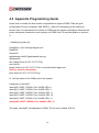
4.4 Appendix Programming Guide
Users have to modify the boot loader configuration to support COM6. Take the grub
configuration file as an example. Add ‘8250.nr_uarts=XX noirqdebug’ at the setting of
kernel. Here, XX represents the number of COM ports the system will support. Because the
power subsystem connects to main system via COM6, the XX must be greater or equal to
6.
1. Modify the grub.conf.
[root@linux ~]# vi /boot/grub/grub.conf
default=0
timeout=5
splashimage=(hd0,0)/grub/splash.xpm.gz
hiddenmenu
title Fedora Core (2.6.27.5.117.FC10)
root (hd0,0)
kernel /vmlinuz-2.6.27.5.117.FC10 ro root=/dev/hda2 rhgb quiet
8250.nr_uarts=6 noirqdebug
initrd /initrd-2.6.27.5.117.FC10.img
2. List the status of the COM ports in the system.
# setserial -g /dev/ttyS*
/dev/ttyS0, UART: 16550A, Port: 0x03f8, IRQ: 4
/dev/ttyS1, UART: 16550A, Port: 0x02f8, IRQ: 3
/dev/ttyS2, UART: 16550A, Port: 0x03e8, IRQ: 11
/dev/ttyS3, UART: 16550A, Port: 0x02e8, IRQ: 10
/dev/ttyS4, UART: 16550A, Port: 0x04f8, IRQ: 11
/dev/ttyS5, UART: 16550A, Port: 0x04e8, IRQ: 10
The node ‘/dev/ttyS5’ corresponds to COM6. The IO port is 0x4e8, IRQ 10.
67
5
OPTIONAL MODULE
INTRODUCTIONS
Acrosser has verified some optional modules for different applications.
brief introduction:
The following is
5.1 GPS Module
Acrosser verify a high performance, low power consumption、small size、very easy
integrated GPS engine board, designed for a broad spectrum of in-vehicle applications.
The GPS engine board will track satellites, provide fast time-to-first-fix and quick navigation
updates.
Features
- Build on high performance and high sensitivity GPS chipset
- Quick Cold Start time and Warm Start time
5.2 Bluetooth Module
Customers can easily connect Bluetooth device with our system.
Features
- High reliable Single Chip Bluetooth System
- Bluetooth 2.1 + EDR support
- Class 2 Bluetooth operation with full 7 slave Piconet support
- Full Speed USB interface compliant with USB V1.1 and compatible with USB V2.0
- Single onboard Antenna connector support
- Simple Pairing, Version 2.1 + EDR to advance its short range wireless technology
- compatible with USB V2.0 Full Speed (12Mbits/s)
5.3 WiFi Module
Acrosser also certify suitable WiFi Module with our system. With this module, customers
can connect with other WiFi network to download and upload data quickly.
68
Features
- IEEE 802.11 b/g/n standards
- PCI Express half-size Mini Card interface
- Up to 150~300 Mbps data rate
- WEP/WPA/WPA2 security
- MIMO technology
- Low power consumption for embedded system
5.4 3.5G Module
When driving on the road, our system can equip with 3.5G module which can connect
wireless network via carrier base station.
Features
- Support GSM/GPRS/EDGE/UMTS/HSDPA
- PCI Express full-size Mini Card interface
5.5 GPIO and CAN bus cable color
PIN
Color
PIN
Color
1
Brown
2
Orange
3
Green
4
Blue
5/6/9
Black
8
White
7
Red/White
10
Purple
11
Light Green
12
Light Blue
13
Pink
14
Brown/White
15
Yellow
PIN
Color
1
white
2
purple
69
FAQ
What kind of programming language has been verified with the bundled source
codes?
Acrosser provides driver and library for development purposes. Customers can refer to
develop their own applications. We have verified them with C, C++ and QT programming
language. For other customized or special programming language, please check with
Acrosser local sales rep. or authorized channels that will help you.
Does it support USB with power adapter hub?
Acrosser recommend to use standard USB hub.
70
Appendix: Technical Support Form
We deeply appreciate you purchase Acrosser products. Please find “tech_form.doc” file in
our utility CD. If you have any questions or problems about Acrosser products, please fill
in the following information: We will answer your questions a.s.a.p.
1) Describe your info and system info
A. Your company name: _____________
B. Your contact info: _________________ & phone number: _________________
C. Your e-mail address: ______________________
D. Your company address: ___________________________________________
__________________________________________
E. Acrosser model name: _____________________
F. Acrosser Serial Number: _____________________
2) Describe system configuration
A. CPU ________________
B. Memory size ___________________
C. Storage (e.g. HDD or CF or SSD) ___________________
D. Extra peripherals (e.g. graphic card) __________________________
E. Operating system & version (e.g. Windows 7 embedded) __________________
F. Special API or driver _________________ (If yes, please provide it for debug,)
G. Running applications _____________________
H. Other _________________________
3) Describe your problems or questions:
4) Send the above info to one of the following Acrosser contact windows:
A. Acrosser local Sales Rep
B. Acrosser authorized channels
C. Acrosser e-mail window --- http://www.acrosser.com/inquiry.html
D. Acrosser FAX number --- 886-2-29992887
71
Acrosser Headquarters
新北市三重區重新路五段609巷12號10樓
10F., No.12, Lane 609, Sec. 5, Chongsin Rd., Sanchong District, New Taipei City 241, Taiwan, R.O.C.
TEL: +886-(0)2-2 9999 000
FAX: +886-(0)2-2999-2887
[email protected]
Acrosser Taichung Office
台中市南屯區河南路四段162號12樓之6
12-6, No.162, Sec. 4, Henan Rd., Nantun Dist., Taichung City 408, Taiwan R.O.C.
TEL: +886-(0)4-2251-0659
FAX: +886-(0)4-2254-6079
Acrosser China Subsidiary
欣扬通电子有限公司 深圳分公司
深圳市福田区车公庙泰然九路21号 皇冠科技园3栋2楼东面A区 (邮编:518040)
A East 2F 3th Building, Crown Estate No.21, 9 Tai-Ran Road, Che Gong Miao, Futian Dist, Shenzhen, China
(Postal:518040)
TEL :+86-0755-83542210/2230/2240/2250/2260
FAX :+86-0755-83700087
Acrosser Shanghai Office
欣扬通电子有限公司 上海分公司
上海市徐汇区零陵路631号爱乐大厦12E (邮编:200085)
12E, Aile Building, No.631, Ling-ling Road, Xu-hui Dist, Shanghai, China (Postal:200085)
TEL :+86-021-64288853
FAX :+86-021-64288854
Acrosser Beijing Office
欣扬通电子有限公司 北京分公司
北京市海淀区安宁庄西三条9号宜品上层2-703(邮编:100085)
Room 2-703,Yipinshangceng,No.9,Xisantiao,Anning Zhuang,Haidian Dist,Beijing (Postal:100085)
TEL :+86-010-82359009
FAX :+86-010-82359003
Acrosser USA Subsidiary
11235 Knott Ave. Suite A, Cypress, CA 90630, USA
Toll Free: +1-866-401-9463
TEL: +1-714-903-1760
FAX: +1-714-903-5629
[email protected]
72