1
AR-B6002 User Manual
AR-B6002 Board
Fan-less with Intel ATOM Pineview + ICH8M
User Manual
Manual Rev.: 1.13
1
AR-B6002 User Manual
Revision 1.13
2
AR-B6002 User Manual
Copyright 2011
All Rights Reserved.
Manual’s first edition:
For the purpose of improving reliability, design and function, the information in this document is
subject to change without prior notice and does not represent a commitment on the part of the
manufacturer.
In no event will the manufacturer be liable for direct, indirect, special, incidental, or
consequential damages arising out of the use or inability to use the product or documentation, even
if advised of the possibility of such damages.
This document contains proprietary information protected by copyright. All rights are reserved.
No part of this Manual may be reproduced by any mechanical, electronic, or other means in any
form without prior written permission of the manufacturer.
Trademarks
AR-B6002 is a registered trademarks of Acrosser; IBM PC is a registered trademark of the
International Business Machines Corporation; Pentium is a registered trademark of Intel
Technologies Inc; Award is a registered trademark of Award Software International Inc; other
product names mentioned herein are used for identification purposes only and may be trademarks
and/or registered trademarks of their respective companies.
3
AR-B6002 User Manual
Table of Contents
1. Introduction .......................................................................................... 6
1.1 Specifications ..................................................................................................7
1.2 Package Contents ...........................................................................................8
1.3 Block Diagram .................................................................................................9
2. H/W Information ................................................................................. 10
2.1 Locations of Connector and Jumper Setting..............................................10
2.2 Connector and Jumper Setting Table ..........................................................13
3. BIos setting ........................................................................................ 23
3.1 Main Setup .....................................................................................................24
3.2 Advanced Chipset Setup ..............................................................................26
3.3 Power Setup...................................................................................................28
3.4 PnP/PCI Setup................................................................................................29
3.5 Peripherals Setup ..........................................................................................31
3.6 PC Health Setup.............................................................................................32
3.7 Boot Setup .....................................................................................................33
3.8 Exit Setup .......................................................................................................34
4. WATCHDOG, GPIO, AND BYPASS PROGRAMMING....................... 36
4.1 Watchdog Programming ...............................................................................36
4.2 GPIO Programming .......................................................................................40
5. SOFTWARE INSTALLATION and PROGRAMMING GUIDE .......... 45
5.1 Introduction....................................................................................................45
5.2 File Descriptions............................................................................................50
4
AR-B6002 User Manual
5.3 API List and Descriptions .............................................................................53
5.4 Appendix ........................................................................................................75
5.5 GPIO and CAN bus cable color ....................................................................76
5
AR-B6002 User Manual
1
INTRODUCTION
AR-V6002FL series with Intel Atom D425/D525 processor is a multi-function In-Vehicle
computer which is suitable for using in all kind of applications. Besides basic I/O ports like VGA,
USB, COM, LAN, and GPIO, AR-V6002FL has complete wireless solutions for selection, embedded
CAN BUS function to allow microcontrollers and devices to communicate with each other in vehicle.
In addition, AR-V6002FL has intelligent power management function with software utility to monitor
power status and control power sequence, and also compliant with most industry standards for
in-vehicle usage including CE, FCC, and E-Mark 13.
6
AR-B6002 User Manual
1.1 Specifications
IntelR Atom D525/D425 1.66GHz
1 x SO-DIMM supports DDRIII up to 4GB(Memory DDR3 data transfer rates of 800 MT/s)
1 x VGA
6 x USB2.0
2 x SATA
1 x CF II
5 x RS-232
1 x GbE (Realtek RTL8111D)
1 x Line-out , 1 x MIC
1 x Canbus (Implementation ISO 11898)
8-bit GPIO with 4in / 4out
Optional WiFi/ Bluetooth/ GPS/ 3.5G solution for selection
Intelligent power management support standard 12V/24V car battery
7
AR-B6002 User Manual
1.2 Package Contents
Check if the following items are included in the package.
Quick Manual
AR-B6002
1 x Software Utility CD
8
AR-B6002 User Manual
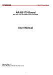
1.3 Block Diagram
9
AR-B6002 User Manual
2
H/W INFORMATION
This chapter describes the installation of AR-B6050. At first, it shows the Function diagram and
the layout of AR-B6050. It then describes the unpacking information which you should read carefully,
as well as the jumper/switch settings for the AR-B6050 configuration
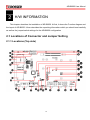
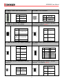
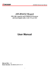
2.1 Locations of Connector and Jumper Setting
2.1.1 Locations (Top side)
10
AR-B6002 User Manual
CN6
CN18
CN23,CN24
CN8
GPIO1
JP8,JP11
SATA_PWR1
CN5
CN25 (Reserve)
SATA_PWR2
CN7
COM5 (Reserve)
CN2
CN28
JP5,JP6 (Reserve)
CN13
CN20
JP7,JP10
BH1
VGA1
JP9,JP12
Minipcie1
SW1
U8
CN9 (Reserve)
COM1
CN21
CN10 (Reserve)
COM3
DIMM1
Minipcie2
AUDIO1
SATA1
CN17
PWR1
SATA2
LED1
FUSE1
11
AR-B6002 User Manual
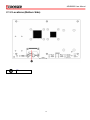
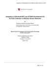
2.1.2 Locations (Bottom Side)
CF1
12
AR-B6002 User Manual
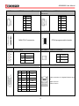
2.2 Connector and Jumper Setting Table
1. CN6: BLUETOOTH connector.
2. CN8: GPS connector.
PIN
DEFINE
PIN
DEFINE
1
GND
1
GND
2
USB_D+
2
USB_D+
3
USB_D-
3
USB_D-
4
+3.3V
4
+3.3V
5
LED
5
LED
6
BT_ON
6
GPS_ON
7
GND
7
GND
8
+3.3V
8
+3.3V
3. SATA_PWR1: SATA Power connector
4. SATA_PWR2: SATA Power connector
PIN
DEFINE
PIN
DEFINE
1
+12V
1
+12V
2
GND
2
GND
3
+3.3V
3
+3.3V
4
+5V
4
+5V
5. CN2: Pin Header for clear CMOS
STATUS
SETTING
1-2
Clear CMOS
7. BH1: CMOS battery holder
6. CN13: SIM Card Slot
SIM Card Slot for 3G Module.
8. MINIPCIE1: Mini PCI-E connector. (for 3.5G
module)
MINI PCI-E connector
CMOS battery holder
13
AR-B6002 User Manual
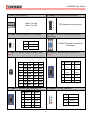
9. CN9: Internal USB2.0 connector (Reserve)
10. CN10: Internal USB2.0 connector
(Reserve)
PIN
DEFINE
PIN
DEFINE
1
+5V
1
+5V
2
USB5-
2
USB6-
3
USB5+
3
USB6+
4
GND
4
GND
5
GND
5
GND
11. MINIPCIE2: Mini PCI-E connector.
12. CN17: FPGA Programmable HEADER.
MINI PCI-E connector.
13. LED1: Power State
FPGA programmable header.
14. CN18: CANBUS connector
LED
SIGNAL
G
PIC LED
G
HDD LED
Y
Power LED
15. GPIO1: GPIO connector
PIN
DEFINE
1
CAN_H
2
CAN_L
16. CN5: RJ45 + USB X 2 connector
PIN
DEFINE
PIN
DEFINE
1
GPO0
2
GPO1
3
GPO2
4
GPO3
5
GND
6
GND
7
GND
8
GND
9
GND
10
GND
11
GPI4
12
GPI5
13
GPI6
14
GPI7
15
N.C
RJ45 connector for Gigabit Ethernet port
#1.
Upper: Port #2.
Lower: Port #1.
14
AR-B6002 User Manual
17. CN7: USB connector
18. CN28: PIC Programming connector.
Upper: Port #4.
Lower: Port #3.
PIC programming connector.
19. CN20: Setting Voltage level of Battery
STATUS
SETTING
1-2
+24V
2-3
+12V (Default).
20. VGA1: D-SUB-15 female connector for
VGA output
D-SUB-15 female connector for
VGA output
21. SW1: DIP switch for power mode select
22. COM1: D-SUB-9P Male connector × 2
(Note 1)
(Note 2)
PIN
DEFINE
PIN
DEFINE
Mode
1
2
3
4
0
ON
ON
ON
ON
1
ON
ON
ON
OFF
2
ON
ON
OFF
ON
3
ON
ON
OFF
OFF
4
ON OFF
ON
ON
5
GND
6
DSR
5
ON OFF
ON
OFF
7
RTS
8
CTS
6
ON OFF
OFF
ON
9
RI_12V
7
ON OFF
OFF
OFF
23. COM3: D-SUB-9P Male connector X 2
DCD
SIN
1
2
/DT-
/DT+
SOUT
DTR
3
4
/422R+
/422R-
24. AUDIO1: AUDIO connector
PIN
DEFINE
PIN
DEFINE
1
DCD
2
SIN
Color
SIGNAL
3
SOUT
4
DTR
Blue
Remote Switch
5
GND
6
DSR
Green
Line Out
7
RTS
8
CTS
Pink
MIC IN
9
RI_12V
15
AR-B6002 User Manual
25. PWR1: Power Input Terminal Block
Connector
PIN
DEFINE
1
12V / 24V
2
IGN
3
GND
27. CN23: RI SELECT for COM1/2
CN24: RI SELECT for COM3/4
STATUS
26. FUSE1: Fuse connector
PIN
DEFINE
1,2
Fuse Out
3,4
Fuse In
28. JP8,JP11: RS-232 / RS-422 / RS-485
Selection for COM1/2 (Note 2)
SETTING
STATUS
SETTING
RS-232
1-3
(Default)
2-4
RI#
1-2(COM1/COM3)
(Default)
+12V
3-4( COM1/COM3)
3-5
RS-422
4-6
RI#
5-6( COM2/COM4)
(Default)
3-5
RS-485
+12V
29. CN25: RI SELECT for COM5/6 (Reserve)
STATUS
4-6
7-8( COM2/COM4)
30. COM5: RS232 signal connector for port #5
(Reserve)
SETTING
PIN
DEFINE
PIN
DEFINE
1
DCD #5
2
DSR #5
3
RX #5
4
RTS #5
5
TX #5
6
CTS #5
7
DTR #5
8
RI #5
9
GND
10
N.C
RI#
1-2(COM5)
(Default)
+12V
3-4(COM5)
RI#
5-6(COM6)
(Default)
+12V
7-8(COM6)
31. JP5,JP6: RS-485 Termination 120 ohm
(Reserve)
32. JP7,JP10: RS-232 / RS-422 / RS-485
Selection for COM1/2 (Note 2)
STATUS
STATUS
SETTING
Enable
short
SETTING
RS-232
1-2
(Default)
open
Disable
RS-422
3-4
RS-485
5-6
(Default)
16
AR-B6002 User Manual
33. JP9,JP12: RS-232 / RS-422 / RS-485
Selection for COM1/2 (Note 2)
STATUS
SETTING
RS-232
1-3
(Default)
2-4
34. U8: SPI BIOS Socket
SPI BIOS Socket
3-5
RS-422
4-6
RS-485
35.
N/A
CN21: BIOS Programmable HEADER.
PIN
DEFINE
PIN
DEFINE
1
CS0
2
+3.3V
3
MISO
4
HOLD
5
WP
6
CLK
7
GND
8
MOSI
9
N.C
10
N.C
37. SATA1: SATA device connector #1.
36. DIMM1: DDR-II SODIMM Socket.
DDR-3 SODIMM Socket
38. SATA2: SATA device connector #2.
SATA device connector #1
SATA device connector #2
39. CF1: Type-II compact flash card socket
+3.3V CF card only and UDMA
mode supported
17
AR-B6002 User Manual
Note1: Power smart function
Mode0: ATX function.
Mode1: Auto PWRBTN function.
Mode2, Mode3, Mode4: Smart ATX.
Mode5, Mode6, Mode7: Smart ATX (poweron by trigger Remote SW).
Others modes are reserved for test only.
Definition
1. Soft off cycle:
A period when received power off signal to generate a off signal (A 500mS pulse, HighLow –High or Low-High-Low depends on SIO configuration, to mother board’s Power
Button Pin)
2. Hard Off cycle:
A period when system off (S5) to stand by removed (G3). In another word, the A period of
5VSB on to off (when system already off)
Notes: S5 and G3 is follow by ACPI
Mode description
The main power-in is controlled by the switch on chassis.
Maximum 16 Modes adjusted by 4 switches. (Mode 8 to mode 15 are reserved for future use).
Mode 0: ATX mode.
A. 5V Standby is always on.
B. Input voltage is not monitored.
C. Power on/off is controlled by remote switch
Mode 1: Auto PWRBTN mode
A. Power output immediately after input is present.
B. Power output is off immediately when input power to off
Smart Mode (Mode 2 to Mode 7)
Mode 2: See Figure 1
A. Power on is controlled by ignition (remote switch does not make any action to power on).
B. Power on retry: If the motherboard cannot be turned on normally (/PSON does not go to low),
the Power smart function will turn off 5VSB, and then turn on 5VSB and retry. Send “on”
18
AR-B6002 User Manual
pulse to motherboard again. The power board will re-try this procedure until successfully turn
on motherboard.
C.
Power smart function sends “ON” pulse to motherboard when ignition is on for more than 2
seconds.
D.
Power smart function will ignore the status change of ignition after ON pulse is send to
motherboard for 3 minutes. After this period, the Power smart function will start to check its
status. This can avoid an improper “OFF” process before the OS is complete booted.
E.
Power off is controlled by remote switch or ignition. Remote switch has higher priority
than ignition. (Remote switch is optional).
F.
Power smart function sends “off” pulse to motherboard 5 seconds after ignition is turned off
or remote switch is pressed. (Soft delay)
G. Power smart function will ignore the status change of ignition and remote switch during the
“OFF” pulse is sent out and the /PSON return to high. This will avoid an improper ON
process before the motherboard is completely shot off.
H. The digital output (optional) will go from high to low at the moment that “OFF” pulse is sent
to motherboard. The low state will be kept until /PSON back to high. If the /PSON does not
back to high within 3 minutes, the Power smart function will enter a retry cycle (described in
next section).
I. Power off retry: If the motherboard cannot be shouted down normally (/PSON does not go to
high) within 3 minutes after “OFF” pulse is sent, the Power smart function will send off pulse
to motherboard again. If the motherboard still cannot be shouted down normally, the power
output will be turned off directly. (Figure 3)
J. Hard off delay: 1 minutes, During this period system can be turned on again if the off
procedure already finished and power button is pushed again(or ignition on again)
Mode 3:
A. Same as mode 2 except for soft/hard off delay time
B. Soft off delay: 1 minute
C.Hard off delay: 5 minutes
Mode 4:
A. Same as mode 2 except for soft/hard off delay time
B. Soft off delay: 30 minute
C.Hard off delay: 2 Hours
19
AR-B6002 User Manual
Mode 5: See Figure 2
Same as mode 2 except that the power on is controlled by remote switch.
A. Power on is controlled by remote switch (ignition must be turned on 2 seconds before
remote switch is pressed).
B. The Smart Mode sends off pulse to motherboard 5 seconds after ignition is turned off or
remote switch is pressed. (Soft delay)
C.Hard off delay: 1 minutes
Mode 6:
A. Same as mode 5 except for soft/hard off and delay
B. Soft off delay: 1 minute
C.Hard off delay: 5 minutes
Mode 7:
A. Same as mode 5 except for soft/hard off and delay
B. Soft off delay: 30 minute
C.Hard off delay: 2 Hours
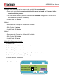
Mode15(Software control mode):
A. Setting by AP
B. Software mode default as Hardware mode 2
C. Soft off delay time can be set
D. Hard off delay time can be set
E. In-Vehicle system power on by ignition or Remote button can be set
F. Show Ignition status / Voltage(for AP only)
G. Create a button "Set default"
Plan AP screen
Engine status
System on by
Car Battery
Ignition
Remote Switch
Soft off delay time
seconds
Hard off delay time
seconds
OK
20
Set Default
Cancel
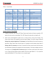
AR-B6002 User Manual
Table 1. Control Mode
Mode
Soft OFF
Hard OFF
Power ON
Delay
delay
Control
Power OFF Control
0 (ATX)
No
No
Remote Switch
Remote Switch
1(Auto PWRBTN)
No
No
DC ON
DC OFF
2
5 seconds
1 minute
Ignition
Ignition / Remote Switch
3
1 minute
5 minutes
Ignition
Ignition / Remote Switch
4
30 minutes
2 hours
Ignition
Ignition / Remote Switch
5
5 seconds
1 minute
Remote Switch
Ignition / Remote Switch
/ Ignition
6
1 minute
5 minutes
Remote Switch
Ignition / Remote Switch
/ Ignition
7
30 minutes
2 hours
Remote Switch
Ignition / Remote Switch
/ Ignition
15 (Software
By user
control)
setting
By user setting
By user setting
Ignition / Remote Switch
Another function of Smart Mode
1.
If ignition turns back “ON” during “Off” Delay, Power smart function will stay in operation. “Off”
signal will not be send to motherboard. The “Off” Delay will re-start after next ignition off.
2.
Power input monitoring(before system boot on, during runtime, during soft off delay): The
Power smart function will constantly monitor the input voltage. If the input voltage is below X
Voltage (the standard might have 5% tolerance), the Smart Mode will not start the power on
procedure. When Power smart function has ran in operation and the battery drops below Y
Voltage (with 5% tolerance) more than 10 seconds the Power smart function will shut down
the motherboard following the standard shut down procedure. If the input voltage recovers in
10 seconds over Y Voltage (with 5% tolerance) again, the Power smart function will continue
to run. (Figure 4)if this happens, ignition shall be off and on again (Mode 2, 3, 4) or press the
remote switch(Mode 5,6,7) if you want to turn on system again.
21
AR-B6002 User Manual
Important: Please make sure the CN20 jumper is set to the right setting which
meet your vehicle power system. The power subsystem uses this setting to
identify the voltage of your vehicle power system.
STATUS
SETTING
1-2
+24V system
2-3
+12V system (Default).
For 12V car battery
For 24V car battery
X value
(Minimum Start up
voltage)
11.2
23
Y value
(Auto shut down voltage)
10.8
22.5
Note2: COM1 / 2 to choose RS-232 / RS-485 / RS-422 by Jump setting
JP7,JP8,JP9 setting to COM1
JP10,JP11,JP12 setting to COM2
Note3:
It can not use USB Hub with power adaptor that connects to USB port.
22
AR-B6002 User Manual
3
BIOS SETTING
This chapter describes the BIOS menu displays and explains how to perform common tasks
needed to get the system up and running. It also gives detailed explanation of the elements found in
each of the BIOS menus. The following topics are covered:
Main Setup
Advanced Chipset Setup
PnP/PCI Setup
Peripherals Setup
PC Health Setup
Boot Setup
Exit Setup
Once you enter the Award BIOS™ CMOS Setup Utility, the Main Menu will appear on the
screen. Use the arrow keys to highlight the item and then use the <Pg Up> <Pg Dn> keys to select
the value you want in each item.
23
AR-B6002 User Manual
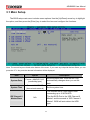
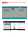
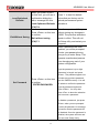
3.1 Main Setup
The BIOS setup main menu includes some options. Use the [Up/Down] arrow key to highlight
the option, and then press the [Enter] key to select the item and configure the functions.
Note: The control keys are listed at the bottom of the menu. If you need any help with the item fields, you can
press the <F1> key, and the relevant information will be displayed.
Item
Option
System Date
Format : MM/DD/YYYY
(month/day/year)
System Time
Format: HH:MM:SS
(hour:minute:second)
IDE Channel 0
Master/Slave
Description
Set the system date. Note that the ‘Day’
automatically changes when you set the
date.
Set the system time.
The onboard SATA Ports support user
connecting up to 2 SATA HDD.
The first SATA Port is the “IDE Channel 0
Master” and the second is “IDE Channel 1
Master”. BIOS will auto-detect the HDD
type.
N/A
24
AR-B6002 User Manual
Halt On
All Errors,
No Errors,
All but keyboard.
Select the situation in which you want the
BIOS to stop the POST process and notify
you.
25
AR-B6002 User Manual
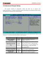
3.2 Advanced Chipset Setup
This section consists of configuration entries that allow you to improve your
system performance, or modify some system features according to your preference. Some entries
are required and reserved by the board’s design.
Note: The control keys are listed at the bottom of the menu. If you need any help with the item fields, you can
press the <F1> key, and the relevant information will be displayed.
Option
Choice
Description
Hyper-Threading
Technology
Enabled
Disabled
Enable for Windows XP and Linux
Disable for other OS.
Quick Power On Self
Test
Enabled
Disabled
This category speeds up the Power On
Self Test (POST) after you have powered
on the computer. If it is set to Enabled, the
BIOS will shorten or skip some check
items during POST.
Full Screen Logo Show
Enabled
Disabled
Select Enabled to show the full screen
logo if you have an add-in BIOS.
On-Chip Frame
Buffer Size
1Mb
8Mb
This Item is for setting the Frame Buffer
(Share system memory as display
26
AR-B6002 User Manual
memory).
DVMT mode
Total GFX
Memory
Enabled
Disabled
128MB
256MB
MAX
This item sets the mode for dynamic video
memory thechology
This item sets the mode for GFX video
memory
27
AR-B6002 User Manual
3.3 Power Setup
Note: The control keys are listed at the bottom of the menu. If you need any help with the item fields, you can
press the <F1> key, and the relevant information will be displayed.
Item
Option
ACPI Function
Enabled
ACPI Suspend
Type
S3
S1
Description
ACPI System Support
ACPI S1/S3 Sleep State.
28
AR-B6002 User Manual
3.4 PnP/PCI Setup
The option configures the PCI bus system. All PCI bus system on the system use INT#, thus
all installed PCI cards must be set to this value.
Note: The control keys are listed at the bottom of the menu. If you need any help with the item fields, you can
press the <F1> key, and the relevant information will be displayed.
Item
Reset Configuration
Data
Resources
Controlled By
Option
Enabled
Disabled
Auto(ESCD)
Manual
Description
Normally, you leave this field Disabled.
Select Enabled to reset Extended System
Configuration Data (ESCD) when you
exit Setup. If you have installed a new
add-on and the system reconfiguration has
caused such a serious conflict, then the
operating system cannot boot.
The Award Plug and Play BIOS has the
capacity to automatically configure all of the
boot and Plug and Play compatible devices.
However, this capability means absolutely
nothing unless you are using a Plug and Play
29
AR-B6002 User Manual
operating system such as Windows 95. If
you set this field to “manual,” then you may
choose specific resources by going into each
of the submenus.
When resources are controlled manually,
IRQ Resources
N/A
assign a type to each system interrupt,
depending on the type of the device that
uses the interrupt
30
AR-B6002 User Manual
3.5 Peripherals Setup
This option controls the configuration of the board’s chipset. Control keys for this screen are
the same as for the previous screen.
Note: The control keys are listed at the bottom of the menu. If you need any help with the item fields, you can
press the <F1> key, and the relevant information will be displayed.
Option
Onboard Serial Port 1
Onboard Serial Port 2
Onboard Serial Port 3
Onboard Serial Port 4
Onboard Serial Port 5
Choice
Description
Serial Port 1: 3F8 / IRQ4
Serial Port 2: 2F8 / IRQ3
Serial Port 3: 3E8 / IRQ11
Serial Port 4: 2E8 / IRQ10
Serial Port 5: 4F8 / IRQ11
Select an address and the
corresponding interrupt for each
serial port.
USB Device Setting
Select your system contains a
Universal Serial Bus (USB)
controller and you have USB
peripherals.
On chip IDE DEVICE
The integrated peripheral controller
contains an IDE interface with
support for two IDE channels.
31
AR-B6002 User Manual
3.6 PC Health Setup
This section shows the parameters in determining the PC Health Status. These parameters
include temperatures, fan speeds, and voltages.
32
AR-B6002 User Manual
3.7 Boot Setup
This option allows user to select sequence/priority of boot device(s) and Boot from LAN.
Note: The control keys are listed at the bottom of the menu. If you need any help with the item fields, you can
press the <F1> key, and the relevant information will be displayed.
Option
First / Second / Third
Boot Device/Other Boot
Device
Choice
Description
Hard Disk
CDROM
USB-FDD
USB-CDROM
LAN
Disabled
The BIOS attempts to load
the operating system from
the devices in the selected
sequence.
LAN Boot Select
Enabled
Disabled
Hard Disk Boot Priority
N/A
33
These fields allow the
system to search for an
OS from LAN.
These fields set the Boot
Priority for each Hard Disk.
AR-B6002 User Manual
3.8 Exit Setup
This option is used to exit the BIOS main menu and change password.
Note: The control keys are listed at the bottom of the menu. If you need any help with the item fields, you can
press the <F1> key, and the relevant information will be displayed.
Option
Save & Exit Setup
Choice
Description
Press <Enter> on this item
to confirm:
Save to CMOS and EXIT
(Y/N)? Y
34
Press “Y” to store the
selections made in the menus
in CMOS – a special section of
the memory that stays on after
you turn your system off. The
next time you boot your
computer, the BIOS configures
your system according to the
setup selections stored in
CMOS. After saving the values,
the system will restart.
AR-B6002 User Manual
Load Optimized
Defaults
When you press <Enter>
on this item, you will see a
confirmation dialog box
with a message like this:
Load Optimized Defaults
(Y/N)? N
Exit Without Saving
Press <Enter> on this item
to confirm:
Quit without saving
(Y/N)? Y
Press ‘Y’ to load the default
values that are factory-set for
optimal-performance system
operations.
This allows you to exit Setup
without storing any changes in
CMOS. The previous selections
remain in effect. This will exit
the Setup utility and restart your
computer.
When a password has been
enabled, you will be prompted
to enter your password every
time you try to enter Setup. This
prevents unauthorized persons
from changing any part of your
system configuration.
Type the password, up to eight
characters in length, and press
<Enter>. The password typed now
Set Password
Press <Enter> on this item
to confirm:
ENTER PASSWORD:
will clear any previous password
from the CMOS memory. You will
be asked to confirm the password.
Type the password again and
press <Enter>. You may also
press <Esc> to abort the selection
and not enter a password.
To disable a password, just press
<Enter> when you are prompted
to enter the password. A message
will confirm that the password will
be disabled. Once the password is
disabled, the system will boot and
you can enter Setup freely.
35
AR-B6002 User Manual
4
WATCHDOG, GPIO, AND BYPASS
PROGRAMMING
4.1 Watchdog Programming
This section describes the usage of WATCHDOG. AR-B6050 integrated the WATCHDOG that
enable user to reset the system after a time-out event. User can use a program to enable the
WATCHDOG and program the timer in range of 1~255 second(s)/minute(s). Once user enables the
WATCHDOG, the timer will start to count down to zero except trigger the timer by user’s program
continuously. After zeroize the timer (stop triggering), the WATCHDOG will generate a signal to
reset the system. It can be used to prevent system crash or hang up. The WATCHDOG is disabled
after reset and should be enabled by user’s program.
Intel also provides a Linux watchdog driver to access the feature on AR-B6050. It can be accessed
via /dev/watchdog. About the related operations of Linux watchdog please refer Linux website.
Please refer to the following table to program WATCHDOG properly, and user could test
WATCHDOG under ‘Debug’ program.
Address port: 2E and Data port: 2F
C:>debug To enter debug mode.
-o 2E 87
-o 2E 01
-o 2E 55
To enter configuration.
-o 2E 55
-o 2E 07
To point to Logical Device Number Reg.
-o 2F 07
To select logical device 7 (WATCHDOG).
-o 2E 72
-o 2F 40
To select “keyboard reset” as WATCHDOG output to reset system.
-o 2E 72
Preparing to select the unit of timer equals minute or second.
-i 2F
To read the value of index “2F”.
-o 2F xx
The value “xx” equals [(value of index “2F”) OR (80)].
OR (80): unit is second.
OR (00): unit is minute.
36
AR-B6002 User Manual
-o 2E 73
Preparing to set the WATCHDOG timer value.
-o 2F ##
The value “##” ranges between 01 ~ FF (1 ~ 255 seconds).
00: To disable WATCHDOG.
To quit debug mode
-q
Notice: The “actual” timer value may not match with the “theoretical”. That is because of the
tolerance of internal oscillating clock and cannot be adjusted or optimized.
//===========================================================================
// Rev
Date
Name
Description
//===========================================================================
// 1.0 11/22/10 Willy W83627HG WatchDog timer test
//===========================================================================
//===========================================================================
// Turbo C++ Version 3.0 Copyright(c) 1990, 1992 by Borland International,Inc.
//===========================================================================
//===========================================================================
// Language include files
//===========================================================================
#include <conio.h>
#include <stdlib.h>
#include <stdio.h>
//===========================================================================
// Assember Types Define
//===========================================================================
typedef unsigned char
BYTE;
typedef unsigned short int WORD;
typedef unsigned long int DWORD;
//===========================================================================
// Extern Function
//===========================================================================
37
AR-B6002 User Manual
//===========================================================================
// Normal procedure
//===========================================================================
void Show_Title()
{
clrscr();
printf("WatchDog Test for W83627HG\n");
printf("1. WDT.EXE 10 s ==--> 10 seconds to reset.\n");
printf("2. WDT.EXE 20 m ==--> 20 minutes to reset.\n");
}
//===========================================================================
// Main procedure
//===========================================================================
int main(int argc, char *argv[])
{
char Time_Format;
BYTE IO_Port_Address=0x2E;
BYTE Time=10;
// Default is 10
BYTE Format=0x00;
// Default is 0x00 = Seconds
if ( argc != 3 )
{ Show_Title();
return 1;
}
clrscr();
textcolor(YELLOW+BLINK);
Time=atoi(argv[1]);
Time_Format=argv[2][0];
if(Time_Format=='m' || Time_Format=='M')
Format=0x08;
// Minutes
if(Time_Format=='s' || Time_Format=='S')
Format=0x00;
// Seconds
// Set Watchdog
38
AR-B6002 User Manual
outportb(IO_Port_Address,0x87); // (EFER) Extended Functions Enable Register
outportb(IO_Port_Address,0x87);
outportb(IO_Port_Address,0x2D); // Point to Global Reg.
// Select Multi-Function pin, (Bit0=0 Watchdog Function)
outportb(IO_Port_Address+1,(inportb(IO_Port_Address+1)&0xFE));
outportb(IO_Port_Address,0x07); // Point to Logical Device Number Reg.
outportb(IO_Port_Address+1,0x08);
// Select logical device 8, (Watchdog Function)
outportb(IO_Port_Address,0x30); // Device Active register
outportb(IO_Port_Address+1,0x01);
outportb(IO_Port_Address,0xF5); // Select Watchdog count mode seconds or minutes
outportb(IO_Port_Address+1,Format); // Default is second
outportb(IO_Port_Address,0xF6); // Set Watchdog Timer Value
outportb(IO_Port_Address+1,Time);
// 0x00 to disable, max 0xFF
while(1)
{
outportb(IO_Port_Address,0xF6);
// Read Watchdog Timer Value
Time=inportb(IO_Port_Address+1);
gotoxy(20,10);
if(Time_Format=='m' || Time_Format=='M')
cprintf(">>> After %d Minutes will reset the system. <<<",Time);
if(Time_Format=='s' || Time_Format=='S')
cprintf(">>> After %d Second will reset the system. <<<",Time);
}
return 0;
}
39
AR-B6002 User Manual
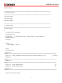
4.2 GPIO Programming
This section describes the usage of GPIOs.
The electrical characteristics of GPIOs and GPIO cable color as following table:
PIN
DEFINE
Color
PIN
DEFINE
Color
1
GPO0
Brown
2
GPO1
Orange
3
GPO2
Green
4
GPO3
Blue
5
GND
Black
6
GND
Black
7
GND
Red / White
8
GND
White
9
GND
Black
10
GND
Purple
11
GPI4
Light Green
12
GPI5
Light Blue
13
GPI6
Pink
14
GPI7
Brown / White
15
N.C
Yellow
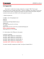
To quickly understand the GPIO programming under Linux, we also provide a sample
application source code in product CD, naming gpio.c. It can be used to control GPIO pin described
above and also LED.
//===========================================================================
// Rev
Date
Name
Description
//===========================================================================
// 1.1 06/30/10 Willy GPIO Test utility for W83627DHG.
//===========================================================================
//===========================================================================
// Turbo C++ Version 3.0 Copyright(c) 1990, 1992 by Borland International,Inc.
//===========================================================================
//===========================================================================
// Language include files
//===========================================================================
#include <conio.h>
#include <stdio.h>
40
AR-B6002 User Manual
#include <dos.h>
//===========================================================================
// Normal procedure
//===========================================================================
void Show_Help();
void Show_Fail();
void Show_Pass();
//===========================================================================
// Main procedure
//===========================================================================
int main(int argc)
{
char *Model_Name="AR-B6002";
char *Version="v1.0";
unsigned char
IO_PORT_BASE=0x2E; // DATA_PORT = IO_PORT_BASE + 1;
unsigned char data;
int result=0;
if ( argc > 1 )
{
Show_Help();
return 1; }
clrscr();
textcolor(WHITE);
gotoxy(1, 1);
cprintf("<>==========================================================================<>");
gotoxy(1, 2); cprintf("|| W83627HF GPIO Test Utility %s Acrosser Technology Co., Ltd.
||",Version);
gotoxy(1, 3);
cprintf("<>==========================================================================<>");
gotoxy(1, 4);
cprintf("<>==========================================================================<>");
gotoxy(1, 5); cprintf("|| Model Name :
||");
gotoxy(1, 6); cprintf("|| SIO IO Base :
||");
gotoxy(1, 7);
cprintf("<>==========================================================================<>");
// Show Got Parameter Informat
41
AR-B6002 User Manual
textcolor(LIGHTGRAY);
gotoxy(18,5); cprintf("%s",Model_Name);
gotoxy(18,6); cprintf("%X",IO_PORT_BASE);
// Enter W83627HF Config
outportb(IO_PORT_BASE,0x87);
outportb(IO_PORT_BASE,0x87);
// Set Multi-function Pins to GPIO
outportb(IO_PORT_BASE,0x2C);
outportb(IO_PORT_BASE+1,(inportb(IO_PORT_BASE+1) & 0x1F));
// Select GPIO Port device
outportb(IO_PORT_BASE,0x07);
outportb(IO_PORT_BASE+1,0x09);
// Set GPIO Port Active GPIO3
outportb(IO_PORT_BASE,0x30);
outportb(IO_PORT_BASE+1,0x02);
// Set W83627HF GPIO30~33 to Output, GPIO34~GPIO37 to Input
outportb(IO_PORT_BASE,0xF0);
outportb(IO_PORT_BASE+1,0xF0);
// inversion data to correct, because the protect circuit
outportb(IO_PORT_BASE,0xF2);
outportb(IO_PORT_BASE+1,0xF0);
// Set W83627HF GPIO30~33 to 0x05
outportb(IO_PORT_BASE,0xF1);
outportb(IO_PORT_BASE+1,0x05);
// Read W83627HF GPIO34~37 Status, if not 0x50 error.
delay(100);
data=inportb(IO_PORT_BASE+1)&0xF0;
if(data!=0x50)
result=1;
// Set W83627HF GPIO30~33 to 0x0A
42
AR-B6002 User Manual
outportb(IO_PORT_BASE,0xF1);
outportb(IO_PORT_BASE+1,0x0A);
// Read W83627HF GPIO34~37 Status, if not 0xA0 error.
delay(100);
data=inportb(IO_PORT_BASE+1)&0xF0;
if(data!=0xA0)
result=1;
// Exit W83627HF Config
outportb(IO_PORT_BASE,0xAA);
if(result)
Show_Fail();
else
Show_Pass();
return result;
}
//===========================================================================
// Function : Show_Help()
// Input
:-
// Change : // Return : // Description : Show Title string.
//===========================================================================
void Show_Help()
{
clrscr();
printf("GPIO Test utility for W83627HF\n\n");
printf("GPIO0 迋芼
奼迋 GPIO1\n");
printf("GPIO2 迋芮芼 奼睿迋 GPIO3\n");
printf("GPIO4 迋芞 ?? 迋 GPIO5\n");
printf("GPIO6 迋迋芞 迋迋 GPIO7\n");
printf("GND
VCC\n");
}
//===========================================================================
43
AR-B6002 User Manual
// Function : Show_Fail()
// Input
:-
// Change : // Return : // Description : Show Fail Message.
//===========================================================================
void Show_Fail()
{
textcolor(LIGHTRED);
gotoxy(20,10);
cprintf(" 詗詗詗詗 詗詗詗
詗詗
詗
");
gotoxy(20,11);
cprintf(" 詗
詗 詗
詗
詗
");
gotoxy(20,12);
cprintf(" 詗詗詗
詗詗詗詗
詗
詗
");
gotoxy(20,13);
cprintf(" 詗
詗
詗
詗
詗
");
gotoxy(20,14);
cprintf(" 詗
詗
詗
詗詗
詗詗詗詗");
}
//===========================================================================
// Function : Show_Pass()
// Input
:-
// Change : // Return : // Description : Show Pass Message.
//===========================================================================
void Show_Pass()
{
textcolor(LIGHTGREEN);
gotoxy(20,10);
cprintf(" 詗詗詗詗 詗詗詗 詗詗詗詗 詗詗詗詗");
gotoxy(20,11);
cprintf(" 詗
gotoxy(20,12);
cprintf(" 詗詗詗詗 詗詗詗詗 詗詗詗詗 詗詗詗詗");
gotoxy(20,13);
cprintf(" 詗
詗
詗
gotoxy(20,14);
cprintf(" 詗
詗
詗 詗詗詗詗 詗詗詗詗");
詗 詗 詗
詗
詗
詗
}
44
");
詗");
AR-B6002 User Manual
5
SOFTWARE INSTALLATION AND
PROGRAMMING GUIDE
5.1 Introduction
5.1.1 CAN bus
Overview
The CAN bus APIs provide interfaces to CAN bus subsystem. By invoking these APIs, programmers can
implement applications which have the functions listed below:
1. Set the BAUD rate.
2. Send the CAN packages over the CAN bus.
3. Receive the CAN packages via the CAN bus hardware interface.
4. Set receive mode to normal, STD only, EXTD only, or any.
5. Set mask
6. Get mask
7. Set filter
8. Get filter
In this CAN bus API package, we provides:
1. On Linux platform:
Linux driver module of CAN bus subsystem and the driver load / unload scripts.
On Windows platform:
Device driver and install program of CAN bus subsystem.
2. API header file.
API libraries in static library format and shared library format.
3. CAN bus test utility and its source code.
Installation Procedure of CAN Bus Driver
On Linux platform:
1. Change to the ‘root’ user account.
2. In the ‘driver’ directory, execute the script ‘install’.
3. Make sure ‘arb6002’ is in the module list.
45
AR-B6002 User Manual
4. If the driver is no longer needed, execute the script ‘uninstall’ to unload the driver.
On Windows platform:
1. In the driver directory, execute the ‘setup.exe’ program.
The CAN bus APIs
Before executing the applications which invoke the CAN bus APIs, users should make sure that the
Linux device driver or the Windows device driver of CAN bus has been installed.
On Linux platform, after successfully installing the device driver, a character device node named
“/dev/can0” will be created automatically. The APIs open the device node “/dev/can0” implicitly so
acquiring a file descriptor of “/dev/can0” by users is not necessary. In order not to degrade the performance
of the CAN bus subsystem, the device node “/dev/can0” is limited to be opened at most once at any moment,
i.e., if application A accesses CAN bus via the APIs, the application B which either tries to open ‘/dev/can0’
or uses CAN bus API will result in failure.
On Windows platform, after successfully installing the device driver, there is a device which shows
‘CAN Bus Driver’ in the ‘Device Manager’. The APIs on Windows platform open this device implicitly.
User can call the APIs directly without opening the CAN Bus subsystem device.
CAN Message Format
// TPE DEFINE
typedef
typedef
typedef
typedef
typedef
typedef
char
unsigned char
short
unsigned short
unsigned long
int
typedef
i8;
u8;
i16;
u16;
u32;
i32;
struct {
i32
i32
u32
struct timeval
i16
u8
} canmsg_t;
flags;
cob;
id;
timestamp;
length;
data[8];
46
AR-B6002 User Manual
To transmit a CAN package, the programmer has to fill in the fields in the variable of type
canmsg_t and pass this canmsg_t variable as an argument to invoke the APIs. The fields in CAN
message are described below:
flags:
This field holds the information of message type. Programmers can set the message type as:
1. Standard Data Frame:
2.
canmsg_t msg; // Declare a variable ‘msg’ of type ‘canmsg_t’
msg.flags = 0; // Setting the flags field to 0 defines the ‘msg’ as an
// ordinary standard data frame.
Extended Data Frame:
canmsg_t msg;
msg.flags = 1 // flags field to 1 defines the ‘msg’ as an
//extend data frame.
cob:
This field is reserved for holding a message communication object number.
id:
CAN message ID.
timestamp:
When a CAN package is received, the CAN device driver will annotate a timestamp to the timestamp
field in the canmsg_t variable and return this canmsg_t variable to the caller.
length:
The number of the data bytes which are sent or received in the ‘data’ field of CAN message. This field
is necessary while transmitting a Standard or Extended Data Frame. Programmers have to explicitly set up
this field. The length of data is 0~8.
For example:
canmsg_t msg;
msg.data[0] = 0xa1;
msg.data[1] = 0xb2;
msg.data[2] = 0xc3;
msg.length = 3;
47
AR-B6002 User Manual
data:
The byte array which holds the message data.
5.1.2 GPIO and Watchdog
Overview
AR-B6002 provides both a GPIO interface and a Watchdog timer. Users can use the GPIO and
Watchdog APIs to configure and to access the GPIO interface and the Watchdog timer. The GPIO
has four input pins and four output pins. The Watchdog timer can be set to 1~255 seconds. Setting
the timer to zero disables the timer. The remaining seconds of the timer to reboot can be read from
the timer.
In this GPIO and Watchdog package, on Linux and Windows platform, we provide:
1. API source code.
2. GPIO and Watchdog test utility and the utility source code.
5.1.3 Power Subsystem
Overview
When the AR-B6002 is at Power Mode 15, the Power Subsystem APIs can be used to get and
set the configuration of power subsystem. By invoking the Power Subsystem APIs, the users
can:
1.
2.
3.
4.
5.
6.
7.
8.
Get the current status of ignition (ON or OFF).
Set the Power-On mode. This setting will be kept in the power subsystem and will take effect
at next system boot.
From the power subsystem, get the stored setting of Power-On mode.
Get or set the time of Hard Off delay in seconds or in minutes.
Get or set the time of Soft Off delay in seconds or in minutes
Get the battery voltage.
Get the version number of the firmware of the Power Subsystem.
Set the Hard Off delay and Soft Off delay to the default value.
48
AR-B6002 User Manual
The power subsystem connects to the main system via the COM6. The Linux’s default
supported COM interfaces are COM1~COM4. The Power Subsystem APIs implicitly communicate
with power subsystem through COM6. Users must take extra steps to configure Linux kernel in
order to support COM6. Please refer to Appendix A for more information. Users don’t need
extraordinary setup on Windows platform to support COM6.
In this Power Subsystem package, we provide:
1. The APIs to access power subsystem and the source code of the APIs.
2. The utility and source code to monitor and set up power modes, ignition status, and power-off
time.
3. On Linux platform, the Makefile to create API libraries and utility.
49
AR-B6002 User Manual
5.2 File Descriptions
5.2.1 CAN Bus
On Linux platform:
1. can.h
The header file of the API and macro definitions.
2. libcan.a
The API library in static library format.
3. libcan.so
The API library in shared library format.
4. can_utility.c
The source code of the utility.
5. Makefile
On Windows platform:
1.
2.
3.
4.
AR-B6002.h
The header file of the APIs and macro definition. This header file is an aggregate header which includes
APIs declarations and macros for CAN Bus, GPIO, Watchdog, and Power Subsystem.
AR-B6002.lib
The API library in static library format. This library is an aggregate library. It includes APIs for CAN
Bus, GPIO, Watchdog, and Power Subsystem.
AR-B6002.dll
The API library in dynamically linked library format. This library is an aggregate library. It includes
APIs for CAN Bus, GPIO, Watchdog, and Power Subsystem.
subdirectory AR_B6002_LIB
The sample project by Microsoft Visual Studio 2010.
5.2.2 GPIO and Watchdog
On Linux platform:
50
AR-B6002 User Manual
1. sio_acce.c
The source code of the Watchdog and GPIO APIs for accessing the SuperIO.
2. sio_acce.h
This file includes the declarations of the APIs and macro definitions.
3. main.c
The source code of the utility.
4. Makefile
On Windows platform:
1.
2.
3.
4.
AR-B6002.h
The header file of the APIs and macro definition. This header file is an aggregate header which
includes APIs declarations and macros for CAN Bus, GPIO, Watchdog, and Power Subsystem.
AR-B6002.lib
The API library in static library format. This library is an aggregate library. It includes APIs for
CAN Bus, GPIO, Watchdog, and Power Subsystem.
AR-B6002.dll
The API library in dynamically linked library format. This library is an aggregate library. It
includes APIs for CAN Bus, GPIO, Watchdog, and Power Subsystem.
subdirectory AR_B6002_LIB
The sample project by Microsoft Visual Studio 2010.
5.2.3 Power Subsystem
On Linux platform:
1.
2.
3.
4.
pwr_acce.c
The source code of the APIs for accessing the power subsystem.
pwr_acce.h
This file includes the declarations of the APIs and macro definitions.
main.c
The source code of the utility.
Makefile
On Windows platform:
51
AR-B6002 User Manual
1.
2.
3.
4.
AR-B6002.h
The header file of the APIs and macro definition. This header file is an aggregate header which includes
APIs declarations and macros for CAN Bus, GPIO, Watchdog, and Power Subsystem.
AR-B6002.lib
The API library in static library format. This library is an aggregate library. It includes APIs for CAN
Bus, GPIO, Watchdog, and Power Subsystem.
AR-B6002.dll
The API library in dynamically linked library format. This library is an aggregate library. It includes
APIs for CAN Bus, GPIO, Watchdog, and Power Subsystem.
subdirectory AR_B6002_LIB
The sample project by Microsoft Visual Studio 2010.
52
AR-B6002 User Manual
5.3 API List and Descriptions
5.3.1 CAN Bus
Under linux platform:
1. Syntax:
void sendCanMessages( canmsg_t *buffer, u8 count )
Description: This function sends out CAN packages over the CAN bus.
Parameters: If there is more than one CAN package to send, these CAN packages are stored in a
‘canmsg_t’ array. This function sends out packages in a sequential fashion. The memory address of the
first CAN package to send is pointed at by the parameter ‘buffer’. The number of CAN packages to send
is indicated by the parameter ‘count’. If the resource of sending out the CAN packages is temporarily
unavailable, the process which invokes this function will be blocked ( Block I/O) until the resource is
available again.
Return Value: None.
2. Syntax:
int getCanMessages( canmsg_t *buffer, u8 count )
Description: This function receives CAN packages from the CAN bus subsystem.
Parameters: This function stores received CAN packages sequentially at an array of type ‘canmsg_t’.
The number of packages to receive is indicated by the parameter ‘count’. Before finishing receiving
‘count’ packages, the process which invokes this function will be temporarily blocked (Block I/O) if
there is no incoming CAN package.
Return Value: If this function receives the packages successfully, it returns 0. If this function fails not 0.
3. Syntax:
int CanSetBaudRate( unsigned long Baud )
53
AR-B6002 User Manual
Description: This function sets up the speed ( Baud rate ) of sending and receiving CAN packages.
Parameters: The parameter ‘Baud’ could be: ( the unit is Kbps )
10 , 20 , 50 , 100 , 125 , 250 , 500 , 800 , 1000
The default speed is 0 Kbps.
Return Value: This function returns 0 if it set the Baud rate successfully. If this function fails not 0.
4. Syntax:
int CanGetBaudRate( unsigned long *Baud )
Description: This function get the speed ( Baud rate ) of sending and receiving CAN packages.
Parameters: The parameter pointer ‘Baud’ record: ( the unit is Kbps )
10 , 20 , 50 , 100 , 125 , 250 , 500 , 800 , 1000
`
Return Value: This function returns 0 if it set the Baud rate successfully. If this function fails not 0.
5. Syntax:
int get_canFd(void)
Description: This function get the File Description number.
Parameters: None.
Return Value: File Description number.
6. Syntax:
int lib_init (void )
Description: This function is used the library call first.
Parameters: None.
Return Value: This function returns 0, library init
successfully. If this function fails not 0.
7. Syntax:
54
AR-B6002 User Manual
int CanStop(void)
Description: This function will stop send and recive can message and into configure mode.
Parameters: None.
Return Value: This function returns 0 if it successfully. If this function fails not 0.
8. Syntax:
int CanStart( void )
Description: This function will resume from configure mode to normal mode.
Parameters: None.
Return Value: This function returns 0 if it set the Baud rate successfully. If this function fails not 0.
9. Syntax:
int setMask(unsigned long mask, int num, int extd_flag)
Description: This function setMask to canbus chip.
Parameters: num 0 is set Mask0, 1 is set Mask1.
extd_flag 1 is 29bit, 0 is 11bit
mask is mask value, if set 11bit the maxmum mask value is 0x7ff,
else the maxmum mask value is 0x1FFFFFFF
Return Value: This function returns 0 if it set the Mask successfully. If this function fails not 0.
10. Syntax:
void getMask(unsigned long *mask, int num, int extd_flag)
Description: This function getMask from canbus chip.
Parameters: num 0 is get Mask0, 1 is get Mask1.
extd_flag 1 is 29bit, 0 is 11bit
55
AR-B6002 User Manual
pointer mask is recored get mask value.
Return Value: None.
11. Syntax:
int setFilter(unsigned long filter, int num, int extd_flag)
Description: This function set Filter to canbus chip.
Parameters: num 0~5 is set filter 0~5.
extd_flag 1 is 29bit, 0 is 11bit
filter is filter value, if set 11bit the maxmum filter value is 0x7ff,
else the maxmum filter value is 0x1FFFFFFF
Return Value: This function returns 0 if it set the Filter successfully. If this function fails not 0.
.
12. Syntax:
void getFilter(unsigned long *filter, int num, int extd_flag)
Description: This function get Filter from canbus chip.
Parameters: num 0~5 is get filter 0~5.
extd_flag 1 is 29bit, 0 is 11bit
pointer filter is recored get filter value
Return Value: None.
.
13. Syntax:
int CanChipReSet(void)
Description: This function to restet canbus chip.
Parameters: None.
Return Value: This function returns 0 if it reset the chipset successfully. If this function fails not 0.
14. Syntax:
int setReciveMode(unsigned long Mode)
56
AR-B6002 User Manual
Description: This function set Recive Mode.
Parameters: Mode 0 is Normal Recive.
Mode 1 is Recive only STD
Mode 2 is Recive only EXTD
Mode 3 is Recive any Message
Return Value: This function returns 0 if it set the Recive Mode successfully. If this function fails not 0.
15. Syntax:
int getReciveMode(unsigned long *Mode)
Description: This function get Recive Mode from can chipset.
Parameters: pointer Mode to recored the Mode from can chipset.
Mode 0 is Normal Recive.
Mode 1 is Recive only STD
Mode 2 is Recive only EXTD
Mode 3 is Recive any Message
Return Value: This function returns 0 if it get the Recive Mode successfully. If this function fails not 0.
16. Syntax:
void lib_close(void)
Description: This function call, when you doesn’t use this library.
Parameters: None.
Return Value: None.
Under windows platform:
1. Syntax:
void sendCanMessages( canmsg_t* buffer, u8 count)
Description: This function sends out CAN packages over the CAN bus.
57
AR-B6002 User Manual
Parameters: If there is more than one CAN package to send, these CAN packages are stored in a
‘canmsg_t’ array. This function sends out packages in a sequential fashion. The memory address of the
first CAN package to send is pointed at by the parameter ‘buffer’. The number of CAN packages to send
is indicated by the parameter ‘count’. If the resource of sending out the CAN packages is temporarily
unavailable, the process which invokes this function will be blocked ( Block I/O) until the resource is
available again.
Return Value: None.
2. Syntax:
int getCanMessages( canmsg_t* buffer, u8 count)
Description: This function receives CAN packages from the CAN bus subsystem.
Parameters: This function stores received CAN packages sequentially at an array of type ‘canmsg_t’.
The number of packages to receive is indicated by the parameter ‘count’. Before finishing receiving
‘count’ packages, the process which invokes this function will be temporarily blocked (Block I/O) if
there is no incoming CAN package.
Return Value: If this function receives the packages successfully, it returns 0. If this function fails not 0.
3. Syntax:
int CanSetBaudRate(unsigned long Baud)
Description: This function sets up the speed ( Baud rate ) of sending and receiving CAN packages.
Parameters: The parameter ‘Baud’ could be: ( the unit is Kbps )
10 , 20 , 50 , 100 , 125 , 250 , 500 , 800 , 1000
The default speed is 0 Kbps.
Return Value: This function returns 0 if it set the Baud rate successfully. If this function fails not 0.
4. Syntax:
int CanGetBauRate(unsigned long *Baud)
Description: This function get the speed ( Baud rate ) of sending and receiving CAN packages.
58
AR-B6002 User Manual
Parameters: The parameter pointer ‘Baud’ record: ( the unit is Kbps )
10 , 20 , 50 , 100 , 125 , 250 , 500 , 800 , 1000
`
Return Value: This function returns 0 if it set the Baud rate successfully. If this function fails not 0.
5. Syntax:
int lib_init(void)
Description: This function is used the library call first.
Parameters: None.
Return Value: This function returns 0, library init
successfully. If this function fails not 0.
6. Syntax:
int CanStop(void)
Description: This function will stop send and recive can message and into configure mode.
Parameters: None.
Return Value: This function returns 0 if it successfully. If this function fails not 0.
7. Syntax:
int CanStart(void)
Description: This function will resume from configure mode to normal mode.
Parameters: None.
Return Value: This function returns 0 if it set the Baud rate successfully. If this function fails not 0.
8. Syntax:
int setMask(unsigned long mask, int num, int extd_flag)
Description: This function setMask to canbus chip.
59
AR-B6002 User Manual
Parameters: num 0 is set Mask0, 1 is set Mask1.
extd_flag 1 is 29bit, 0 is 11bit
mask is mask value, if set 11bit the maxmum mask value is 0x7ff,
else the maxmum mask value is 0x1FFFFFFF
Return Value: This function returns 0 if it set the Mask successfully. If this function fails not 0.
9. Syntax:
void getMask(unsigned long *mask, int num, int extd_flag)
Description: This function getMask from canbus chip.
Parameters: num 0 is get Mask0, 1 is get Mask1.
extd_flag 1 is 29bit, 0 is 11bit
pointer mask is recored get mask value.
Return Value: None.
10. Syntax:
int setFilter(unsigned long filter, int num, int extd_flag)
Description: This function set Filter to canbus chip.
Parameters: num 0~5 is set filter 0~5.
extd_flag 1 is 29bit, 0 is 11bit
filter is filter value, if set 11bit the maxmum filter value is 0x7ff,
else the maxmum filter value is 0x1FFFFFFF
Return Value: This function returns 0 if it set the Filter successfully. If this function fails not 0.
.
11. Syntax:
void getFilter(unsigned long *filter, int num, int extd_flag)
Description: This function get Filter from canbus chip.
Parameters: num 0~5 is get filter 0~5.
60
AR-B6002 User Manual
extd_flag 1 is 29bit, 0 is 11bit
pointer filter is recored get filter value
Return Value: None.
.
12. Syntax:
int CanChipReSet(void)
Description: This function to restet canbus chip.
Parameters: None.
Return Value: This function returns 0 if it reset the chipset successfully. If this function fails not 0.
13. Syntax:
int setReciveMode(unsigned long Mode)
Description: This function set Recive Mode.
Parameters: Mode 0 is Normal Recive.
Mode 1 is Recive only STD
Mode 2 is Recive only EXTD
Mode 3 is Recive any Message
Return Value: This function returns 0 if it set the Recive Mode successfully. If this function fails not 0.
14. Syntax:
int getReciveMode(unsigned long *Mode)
Description: This function get Recive Mode from can chipset.
Parameters: pointer Mode to recored the Mode from can chipset.
Mode 0 is Normal Recive.
Mode 1 is Recive only STD
Mode 2 is Recive only EXTD
Mode 3 is Recive any Message
Return Value: This function returns 0 if it get the Recive Mode successfully. If this function fails not 0.
61
AR-B6002 User Manual
15. Syntax:
void lib_close(void)
Description: This function call, when you doesn’t use this library.
Parameters: None.
Return Value: None.
5.3.2 GPIO and Watchdog
GPIO
Under linux platform:
1. Syntax:
i32 getInChLevel( i32 channel, u8 *val )
Description: Get the value of GPIO Input and put the value at *val.
Parameters:
I. The parameter ‘channel’ indicates the GPIO Input pins to show. Users can use the macros GPI0,
GPI1, GPI2, GPI3 to indicate the GPIO Input channel. For example:
getInChLevel( GPI2, &val); // Indicate the GPIO Input channel 2
getInChLevel( GPI0 | GPI3, &val); // Indicate the GPIO Input
// channel 0 and channel 3
II.
The parameter ‘val’ is an unsigned character pointer. The function puts the values of the indicated
GPIO channels at the memory pointed by ‘val’. The bit 0 of *val shows the value of GPIO Input
channel 0. The bit 1 of *val shows the value of GPIO Input channel 1. Other bits show the
corresponding GPIO Input channels. Because there are only four channels, bit 4 ~ bit 7 of *val are
always zero.
Here is an example:
If GPIO Input channel 1 and channel 3 are both 1.
62
AR-B6002 User Manual
unsigned char ch;
getInChLevel( GPI1|GPI3, &ch );
The returned value of variable ‘ch’ is 0xa.
Return Value: If the function gets the values successfully, it returns 0. If any error, it returns –1.
2. Syntax:
i32 setOutChLevel( i32 channel, u8 val )
Description: Set the value of GPIO Output according to the variable ‘val’.
Parameters:
I. The parameter ‘channel’ indicates the GPIO Output pins to set. Users can use the macros GPO0,
GPO1, GPO2, GPO3 to indicate the GPIO Output channels.
II. The parameter ‘val’ indicate the value to be set to GPIO Output channel. The acceptable values is
limited to 0 and 1.
For example:
/* Setting the GPIO Output channel 2 to 1 */
setOutChLevel( GPO2, 1 );
/* Setting the GPIO Output channel 0 and channel 3 to 0 */
getInChLevel( GPO0 | GPO3, 0 );
Return Value: If the function sets the values successfully, it returns 0. If any error, it returns –1.
3. Syntax:
i32 getOutchLevel( i32 channel, u8 *val )
Description: Get the value of GPIO Output and put the value at *val.
Parameters:
I. The parameter ‘channel’ indicates the GPIO Output pins to show. Users can use the macros GPO0,
GPO1, GPO2, GPO3 to indicate the GPIO Output channel. For example:
getOutChLevel( GPO2, &val); // Indicate the GPIO Output channel 2
63
AR-B6002 User Manual
/* Indicate the GPIO Output channel 0 and channel 3. */
getOutChLevel( GPO0 | GPO3, &val);
II.
The parameter ‘val’ is an unsigned character pointer. The function puts the values of the indicated
GPIO channels at the memory pointed by ‘val’. The bit 0 of *val shows the value of GPIO Output
channel 0. The bit 1 of *val shows the value of GPIO Output channel 1. Other bits show the
corresponding GPIO Output channels. Because there are only four channels, bit 4 ~ bit 7 of *val
are always zero.
Here is an example:
If GPIO Output channel 0 and channel 2 are both 1.
unsigned char ch;
getOutChLevel( GPO0|GPO2, &ch );
The returned value of variable ‘ch’ is 0x5.
Return Value: If the function gets the values successfully, it returns 0. If any error, it returns –1.
Under windows platform:
1. Syntax:
int getGPIOBitValue(int iBitNumber, bool * bValue)
Description: Get the value of GPIO and put the value at * bValue.
Parameters:
I. The parameter ‘iBitNumber indicates the GPIO Input pins to show. Users can use the macros
GPO_BIT_0, GPO_BIT_1, GPO_BIT_2, GPO_BIT_3, GPI_BIT_4, GPI_BIT_5, GPI_BIT_6, or
GPI_BIT_7 to indicate the GPIO channel. For example:
getGPIOBitValue (GPO_BIT_0, &val);
// Indicate the GPIO Output channel 0
getGPIOBitValue (GPI_BIT_6, &val);
// Indicate the GPIO Input channel 6
II.
The parameter ‘bValue’ is an bool pointer. The function puts the values of the indicated GPIO
channels at the memory pointed by ‘bValue’. True indicates HI, and false indicates LOW.
64
AR-B6002 User Manual
Return Value: If the function gets the values successfully, it returns 0. If any error, it returns not zero.
2. Syntax:
int setGPIOBitValue(int iBitNumber, bool bValue)
Description: Set the value of GPIO Output according to the variable ‘bValue’.
Parameters:
I. The parameter ‘channel’ indicates the GPIO Output pins to set. Users can use the macros
GPO_BIT_0, GPO_BIT_1, GPO_BIT_2, or GPO_BIT_3 to indicate the GPIO Output channels.
II. The parameter ‘bValue’ indicate the value to be set to GPIO Output channel. True indicates HI, and
false indicates LOW.
For example:
/* Setting the GPIO Output channel 2 to HI */
setGPIOBitValue (GPO_BIT_2, true );
/* Setting the GPIO Output channel 3 to LOW */
setGPIOBitValue (GPO_BIT_3, false );
Return Value: If the function sets the values successfully, it returns 0. If any error, it returns not zero.
Watchdog
Under linux platform:
1. Syntax:
u8 getWtdTimer(void)
Description: This function read the value of the watchdog time counter and return it to the caller.
Parameters: None.
Return Value: This function return the value of the time counter and return it to the caller as an
unsigned integer.
65
AR-B6002 User Manual
2. Syntax:
void setWtdTimer( u8 val )
Description: This function sets the watchdog timer register to the value ‘val’ and starts to count down.
The value could be 0 ~ 255. The unit is second. Setting the timer register to 0 disables the watchdog
function and stops the countdown.
Parameters: The parameter ‘val’ is the value to set to watchdog timer register. The range is 0 ~ 255.
Return Value: None.
Under windows platform:
1. Syntax:
int readWatchdog(unsigned char * pucValue)
Description: This function read the value of the watchdog time counter and return it to the caller.
Parameters: The parameter ‘pucValue’ is an unsigned character pointer. The function puts the values
read from watchdog at the memory pointed by ‘pucValue’.
Return Value: If the function gets the values successfully, it returns 0. If any error, it returns not zero.
2. Syntax:
int startWatchdog(unsigned char ucUnit, unsigned char ucValue)
Description: This function sets the watchdog timer register to the value ‘ucValue’ and starts to count
down. The value could be 0 ~ 255. The unit is second. Setting the timer register to 0 disables the
watchdog function and stops the countdown.
Parameters: The parameter ‘ucUnit’ is the unit to set to watchdog timer register. ‘0’ indicates second.
And ‘1’ indicates minute. The parameter ‘ucValue’ is the value to set to watchdog timer register. The
range is 0 ~ 255.
Return Value: If the function gets the values successfully, it returns 0. If any error, it returns not zero.
5.3.3 Power Subsystem
Under linux platform:
1. Syntax:
i32 getIgnStatus( u8 *ignStatus )
66
AR-B6002 User Manual
Description: Get the current ignition status. The ignition has two statuses: ON or OFF.
Parameters: This function puts the ignition status at the memory pointed by the unsigned character
pointer ‘ignStatus’. If the returned status is 0xa5, the ignition is ON. If the returned status is 0x5a, the
ignition is OFF. There are macros of Ignition ON and Ignition OFF in pwr_acce.h.
Return Value: If the function gets the ignition status and put it at the memory pointed by the argument
successfully, this function will return 0. If any error, the function returns –1.
2. Syntax:
i32 setSoftOffDelayS( u32 setTime )
Description: The Soft Off Delay is the interval between that the system receives a power off signal and
that the system generates a power off signal. This function sets up the interval in seconds.
Parameters: The parameter is of the type of unsigned long. The value of the parameter ranges from
0~255. The unit of the value of the parameter is seconds.
Return Value: If the function sets the delay time successfully, it will return 0. If any error, the function
returns –1.
3. Syntax:
i32 setSoftOffDelayM( u32 setTime )
Description: The Soft Off Delay is the interval between that the system receives a power off signal and
that the system generates a power off signal. This function sets up the interval in minutes.
Parameters: The parameter is of the type of unsigned long. The value of the parameter ranges from
0~255. The unit of the value of the parameter is minutes.
Return Value: If the function sets the delay time successfully, it will return 0. If any error, the function
returns –1.
4. Syntax:
i32 setHardOffDelayS( u32 setTime )
Description: The Hard Off Delay is the interval between that the system is off and that the power 5VSB
is off. This functions set up the interval in seconds.
Parameters: The parameter is of the type of unsigned long. The value of the parameter ranges from
0~255. The unit of the value of the parameter is seconds.
.
Return Value: If the function sets the delay time successfully, it will return 0. If any error, the function
67
AR-B6002 User Manual
returns –1.
5. Syntax:
i32 setHardOffDelayM( u32 setTime )
Description: The Hard Off Delay is the interval between that the system is off and that the power 5VSB
is off. This functions set up the interval in minutes.
Parameters: The parameter is of the type of unsigned long. The value of the parameter ranges from
0~255. The unit of the value of the parameter is minutes.
.
Return Value: If the function sets the delay time successfully, it will return 0. If any error, the function
returns –1.
6. Syntax:
i32 setPowerOnMode( u8 powerOnMode )
Description: The function sets up the source of the boot-up signal of the system. There are two choices:
boot from the Ignition or boot from the Remote Switch.
Parameters:
PowerOnMode = 0xa5, boot up by the Ignition.
PowerOnMode = 0x5a, boot up by the Remote Switch.
There are macros of Ignition mode and Remote Switch mode in pwr_acce.h (Linux) and
AR-B6002.h(Windows).
Return Value: If the function sets power-on mode successfully, it will return 0. If any error, the function
returns –1.
7. Syntax:
i32 getSoftOffDelay( u32 *Time )
Description: The Soft Off Delay is the interval between that the system receives a power off signal and
that the system generates a power off signal. This function gets the interval.
Parameters: The parameter is a pointer which points to an unsigned long variable. The returned value is
stored at this variable. The unit of the returned value is in seconds.
Return Value: If the delay time is returned successfully, the function returns 0. If any error, it returns –1.
68
AR-B6002 User Manual
8. Syntax:
i32 getHardOffDelay( u32 *Time )
Description: The Hard Off Delay is the interval between that the system is off and that the power 5VSB
is off. This function gets the interval.
Parameters: The parameter is a pointer which points to an unsigned long variable. The returned value is
stored at this variable. The unit of the returned value is in seconds.
Return Value: If the delay time is returned successfully, the function returns 0. If any error, it returns –1.
9. Syntax:
i32 getPowerOnMode( u8 *powerOnMode )
Description: The function gets the setting of power-on mode. There are two modes: boot from the
Ignition or boot from the Remote Switch.
Parameters: The parameter is a pointer which points to an unsigned character. The returned code is
stored at this memory. There are two power-on modes:
PowerOnMode = 0xa5, boot up by the Ignition.
PowerOnMode = 0x5a, boot up by the Remote Switch.
Return Value: If the power-on mode is returned successfully, the function returns 0. If any error, it
returns –1
10. Syntax:
i32 getBattVolt( float *volt )
Description: The function gets the voltage reading of the battery.
Parameters: The parameter ‘volt’ is a pointer which points to an variable of type ‘float’. The unit of the
returned value is voltage.
Return Value: If the reading of voltage is returned successfully, the function returns 0. If any error, it
returns –1
11. Syntax:
i32 getPicFwVer( struct PicInfo *ver )
Description: The function gets version information of Power Subsystem firmware.
69
AR-B6002 User Manual
Parameters: The parameter is a pointer which points to a ‘PicInfo’ structure, which consists of 9
unsigned characters. Here is the definition of structure ‘PicInfo’:
type struct {
u8 type[3];
// The type of the power subsystem
u8 mode[4]; // The mode at which the power subsystem is
operating.
u8 majorVersion; // Major version number of the firmware
u8 minorVersion; // Minor version number of the firmware
} PicInfo;
PicInfo picInfo;
getPicFwVer( &picInfo );
printf(“%c.%c\n”, picInfo.majorVersion, picInfo.minorVersion );
Return Value: If the version information is returned successfully, the function returns 0. If any error, it
returns –1.
12. Syntax:
i32 getPicMode( u8 *mode )
Description: The function gets the mode number at which the Power Subsystem is operating..
Parameters: The parameter is a pointer which points to a variable of type ‘unsigned char’. The returned
mode number is put at the memory which is pointed by parameter ‘mode’.
Return Value: If the mode information is returned successfully, the function returns 0. If any error, it
returns –1
13. Syntax:
i32 setPicDefault( void )
Description: The function restores the SoftOffDelay and HardOffDelay to the default value.
Parameters: None.
Return Value: If this function works successfully, the function will return 0. If any error, it will
return –1.
70
AR-B6002 User Manual
Under windows platform:
1. Syntax:
BOOL PowerPic_GetIgnitionStatus( BYTE* pStatus )
Description: Get the current ignition status. The ignition has two statuses: ON or OFF.
Parameters: This function puts the ignition status at the memory pointed by the BYTE pointer ‘pStatus’.
If the returned status is 0xa5, the ignition is ON. If the returned status is 0x5a, the ignition is OFF. There
are macros of Ignition ON and Ignition OFF.
Return Value: If the function gets the ignition status and put it at the memory pointed by the argument
successfully, this function will return TRUE. If any error, the function returns FALSE.
2. Syntax:
BOOL PowerPic_SetSoftOffDelayTime( int nTime, int nTimeUnit )
Description: The Soft Off Delay is the interval between that the system receives a power off signal and
that the system generates a power off signal.
Parameters: The parameter ‘nTime‘ is the value to set as delay interval. The value of the parameter
‘nTime‘ ranges from 0~255. The parameter ‘nTimeUnit‘ is the unit of nTime. Users can use macros
TIME_UNIT_SECOND or TIME_UNIT_MINUTE to indicate unit.
Return Value: If the function sets the soft off delay successfully, this function will return TRUE. If any
error, the function returns FALSE.
3. Syntax:
BOOL PowerPic_SetHardOffDelayTime( int nTime, int nTimeUnit )
Description: The Hard Off Delay is the interval between that the system is off and that the power 5VSB
is off.
Parameters: The parameter ‘nTime‘ is the value to set as delay interval. The value of the parameter
‘nTime‘ ranges from 0~255. The parameter ‘nTimeUnit‘ is the unit of nTime. Users can use macros
TIME_UNIT_SECOND or TIME_UNIT_MINUTE to indicate unit.
.
Return Value: If the function sets the hard off delay successfully, this function will return TRUE. If any
error, the function returns FALSE.
4. Syntax:
71
AR-B6002 User Manual
BOOL PowerPic_SetPowerOnMode( BYTE
bMode )
Description: The function sets up the source of the boot-up signal of the system. There are two choices:
boot from the Ignition or boot from the Remote Switch.
Parameters:
bMode = 0xa5, boot up by the Ignition.
bMode = 0x5a, boot up by the Remote Switch.
There are macros of Ignition mode and Remote Switch mode in pwr_acce.h (Linux) and
AR_B6002_LIB.h(Windows).
Return Value: If the function sets the power on mode successfully, this function will return TRUE. If
any error, the function returns FALSE.
5. Syntax:
BOOL PowerPic_GetSoftOffDelayTime( int* pSeconds )
Description: The Soft Off Delay is the interval between that the system receives a power off signal and
that the system generates a power off signal. This function gets the interval.
Parameters: The parameter ‘pSeconds‘ is a pointer which points to an int variable. The returned value is
stored at this variable. The unit of the returned value is in seconds.
Return Value: If the function gets the soft off delay successfully, this function will return TRUE. If any
error, the function returns FALSE.
6. Syntax:
BOOL PowerPic_GetHardOffDelayTime( int* pSeconds )
Description: The Hard Off Delay is the interval between that the system is off and that the power 5VSB
is off. This function gets the interval.
Parameters: The parameter ‘pSeconds’ is a pointer which points to an int variable. The returned value is
stored at this variable. The unit of the returned value is in seconds.
Return Value: If the function gets the hard off delay successfully, this function will return TRUE. If any
error, the function returns FALSE.
7. Syntax:
72
AR-B6002 User Manual
BOOL PowerPic_GetPowerOnMode( BYTE* pMode )
Description: The function gets the setting of power-on mode. There are two modes: boot from the
Ignition or boot from the Remote Switch.
Parameters: The parameter ‘pMode’ is a pointer which points to an BYTE. The returned code is stored
at this memory. There are two power-on modes:
* pMode = 0xa5, boot up by the Ignition.
* pMode = 0x5a, boot up by the Remote Switch.
Return Value: If the function gets the power in mode successfully, this function will return TRUE. If
any error, the function returns FALSE.
8. Syntax:
BOOL PowerPic_GetBatteryVoltage( float *pVoltage )
Description: The function gets the voltage reading of the battery.
Parameters: The parameter ‘pVoltage’ is a pointer which points to an variable of type ‘float’. The unit of
the returned value is voltage.
Return Value: If the function gets the battery voltage successfully, this function will return TRUE. If
any error, the function returns FALSE.
9. Syntax:
BOOL PowerPic_GetFirmwareVersion( T_PIC_INFO *pPicInfo )
Description: The function gets version information of Power Subsystem firmware.
Parameters: The parameter is a pointer which points to a ‘T_PIC_INFO’ structure, which consists of 9
BYTE. Here is the definition of structure ‘T_PIC_INFO’:
type struct {
typedef struct _T_PIC_INFO {
BYTE PicType[ 3 ];
BYTE PicModel[ 4 ];
BYTE PicMajorVersion;
BYTE PicMinorVersion;
} T_PIC_INFO;
73
AR-B6002 User Manual
Return Value: If the function gets the firmware version successfully, this function will return TRUE. If
any error, the function returns FALSE.
10. Syntax:
BOOL PowerPic_GetPicMode( BYTE* pMode )
Description: The function gets the mode number at which the Power Subsystem is operating..
Parameters: The parameter is a pointer which points to a variable of type ‘BYTE’. The returned mode
number is put at the memory which is pointed by parameter ‘pMode’.
Return Value: If the function gets the PIC mode successfully, this function will return TRUE. If any
error, the function returns FALSE.
11. Syntax:
BOOL PowerPic_SetDefaultValue()
Description: The function restores the SoftOffDelay and HardOffDelay to the default value.
Parameters: None.
Return Value: If the function sets the default value successfully, this function will return TRUE. If any
error, the function returns FALSE.
74
AR-B6002 User Manual
5.4 Appendix
Users have to modify the boot loader configuration to support COM6. Take the grub
configuration file as an example. Add ‘8250.nr_uarts=XX noirqdebug’ at the setting of kernel. Here,
XX represents the number of COM ports the system will support. Because the power subsystem
connects to main system via COM6, the XX must be greater or equal to 6.
1. Modify the grub.conf.
[root@linux ~]# vi /boot/grub/grub.conf
default=0
timeout=5
splashimage=(hd0,0)/grub/splash.xpm.gz
hiddenmenu
title Fedora Core (2.6.27.5.117.FC10)
root (hd0,0)
kernel /vmlinuz-2.6.27.5.117.FC10 ro root=/dev/hda2 rhgb quiet
8250.nr_uarts=6 noirqdebug
initrd /initrd-2.6.27.5.117.FC10.img
2. List the status of the COM ports in the system.
# setserial -g /dev/ttyS*
/dev/ttyS0, UART: 16550A, Port: 0x03f8, IRQ: 4
/dev/ttyS1, UART: 16550A, Port: 0x02f8, IRQ: 3
/dev/ttyS2, UART: 16550A, Port: 0x03e8, IRQ: 11
/dev/ttyS3, UART: 16550A, Port: 0x02e8, IRQ: 10
/dev/ttyS4, UART: 16550A, Port: 0x04f8, IRQ: 11
/dev/ttyS5, UART: 16550A, Port: 0x04e8, IRQ: 10
The node ‘/dev/ttyS5’ corresponds to COM6. The IO port is 0x4e8, IRQ 10.
75
AR-B6002 User Manual
5.5 GPIO and CAN bus cable color
PIN
Color
PIN
Color
1
Brown
2
Orange
3
Green
4
Blue
5/6/9
Black
8
White
7
Red/White
10
Purple
11
Light Green
12
Light Blue
13
Pink
14
Brown/White
15
Yellow
PIN
Color
1
white
2
purple
76