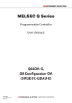
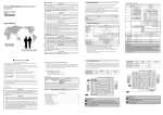
1
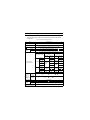
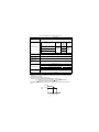
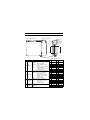
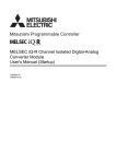
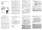
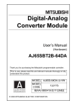
Channel Isolated
Digital-Analog Converter Module
User’s Manual
(Hardware)
Q66DA-G
Thank you for buying the Mitsubishi general-purpose programmable
logic controller MELSEC-Q Series.
Prior to use, please read both this manual and detailed manual
thoroughly and familiarize yourself with the product.
MODEL
Q-66D/A-G-U-HW
MODEL
CODE
13JY12
IB(NA)-0800362-C(0610)MEE
© 2006 MITSUBISHI ELECTRIC CORPORATION
SAFETY PRECAUTIONS
(Read these precautions before using.)
When using Mitsubishi equipment, thoroughly read this manual and the
associated manuals introduced in the manual. Also pay careful attention to safety
and handle the module properly.
These precautions apply only to Mitsubishi equipment. Refer to the user's manual
of the CPU module to use for a description of the PLC system safety precautions.
These SAFETY PRECAUTIONS classify the safety precautions into two
categories: "DANGER" and "CAUTION".
DANGER
Procedures which may lead to a dangerous condition
and cause death or serious injury if not carried out
properly.
CAUTION
Procedures which may lead to a dangerous condition
and cause superficial to medium injury, or physical
damage only, if not carried out properly.
Depending on circumstances, procedures indicated by
CAUTION may
also be linked to serious results.
In any case, it is important to follow the directions for usage.
Store this manual in a safe place so that you can take it out and read it whenever
necessary. Always forward it to the end user.
[DESIGN PRECAUTIONS]
DANGER
z Do not bunch the control wires or communication cables with the main circuit
or power wires, or install them close to each other.
They should be installed 100 mm (3.94 inch) or more from each other.
Not doing so could result in noise that may cause malfunction.
z At power ON/OFF, voltage or current may instantaneously be output from the
output terminal of this module.
In such case, wait until the analog output becomes stable to start controlling
the external device.
A-1
[INSTALLATION PRECAUTIONS]
CAUTION
z Use the PLC in an environment that meets the general specifications given in
the User's Manual of the CPU module being used.
Using this PLC in an environment outside the range of the general
specifications may cause electric shock, fire, malfunction, and damage to or
deterioration of the product.
z While pressing the installation lever located at the bottom of module, insert the
module fixing tab into the fixing hole in the base unit until it stops.
Improper installation may result in malfunction, breakdown or the module
coming loose and dropping. After mounting the module to the base unit
securely hold the module with module fixing bracket.
z Tighten the screws within the range of specified torque.
If the screws are loose, it may cause the module to fallout, short circuits, or
malfunction.
If the screws are tightened too much, it may cause damage to the screw and/
or the module, resulting in fallout, short circuits or malfunction.
z Be sure to shut off all phases of the external power supply used by the system
before mounting or removing the module.
Not doing so may cause damage to the module.
z Do not directly touch the conductive area or electronic components of the
module.
Doing so may cause malfunction or failure in the module.
[WIRING PRECAUTIONS]
CAUTION
z Always ground the FG terminal for the PLC.
There is a risk of electric shock or malfunction.
z Be careful not to let foreign matters such as sawdust or wire chips get inside
the module.
These may cause fires, failure or malfunction.
z The top surface of the module is covered with protective film to prevent
foreign objects such as cable offcuts from entering the module when wiring.
Do not remove this film until the wiring is complete.
Before operating the system, be sure to remove the film to provide adequate
heat ventilation.
A-2
Revisions
* The manual number is given on the bottom right of the cover.
Print Date
*Manual Number
Revision
Aug., 2006
IB(NA)-0800362-A First edition
Sep., 2006
IB(NA)-0800362-B Correction
Chapter 2, Section 5.3
Oct., 2006
IB(NA)-0800362-C Correction
Chapter 2, Section 5.3, Chapter 6
This manual confers no industrial property rights or any rights of any other kind,
nor does it confer any patent licenses. Mitsubishi Electric Corporation cannot be
held responsible for any problems involving industrial property rights which may
occur as a result of using the contents noted in this manual.
© 2006 MITSUBISHI ELECTRIC CORPORATION
A-3
CONTENTS
1. Overview ........................................................................................................ 1
2. Performance Specifications ........................................................................... 2
3. Part Names .................................................................................................... 4
4. Handling Precautions ..................................................................................... 5
4.1 Mounting module fixing bracket ............................................................... 5
5. Wiring ............................................................................................................. 6
5.1 Wiring precautions ................................................................................... 6
5.2 External wiring ......................................................................................... 7
5.3 Switch setting for intelligent functional module ........................................ 8
6. External Dimensions ...................................................................................... 9
A-4
About This Manual
The following manuals are also related to this product.
Order them if necessary.
Relevant Manual
Manual name
Manual Number
(Model code)
Channel Isolated Digital-Analog Converter Module User's
ManualQ66DA-G / GX Configurator-DA
SH-080648ENG
(13JR97)
Conformance to the EMC Directive/Low Voltage Directive
When incorporating the Mitsubishi PLC into other machinery or equipment and
keeping compliance with the EMC and low voltage directives, refer to Chapter 3,
"EMC Directives and Low Voltage Directives" of the User's Manual (Hardware)
included with the CPU module or base unit used.
The CE logo is printed on the rating plate on the main body of the PLC that
conforms to the EMC directive and low voltage instruction.
By making this product conform to the EMC directive and low voltage instruction,
it is not necessary to make those steps individually.
A-5
1. Overview
This manual explains specifications and the names of the components and
handling for the type Q66DA-G channel isolated digital-analog converter
module (hereafter Q66DA-G) which are used in combination with the
MELSEC-Q Series CPU module.
After unpacking, confirm that the following products are enclosed.
Table 1.1 Packing list
Model code
Quantity
Q66DA-G
1
FG terminal L-Shaped metal fitting
1
1
2. Performance Specifications
The specifications for the Q66DA-G are shown in the following table. For
general specifications, refer to the operation manual for the CPU module
being used.
Table 2.1 Performance Specifications
Item
Specifications
Number of analog output
points
6 points (6 channels)
16-bit signed binary (normal resolution mode:-4096 to 4095
high resolution mode: -12288 to 12287, -16384 to 16383)
Digital input
Using scaling function
Analog
output
16-bit signed binary (-32768 to 32767)
Voltage
-12 to 12VDC (External load resistance: 1k to 1M )
Current
0 to 20mADC (External load resistance: 0 to 600 )
0 to 22mADC (External load resistance: refer to *3)
Analog output range
0 to 5V
Digital input
value
-10 to 10V
0 to 12000
-16000 to
16000
2.5mV
User range
setting 2
Current
-4000 to
4000
0.75mV
4 to 20mA
0 to 4000
Within
-4000 to
4000
A
4
A
1.5
0.1% (Voltage:
Temperatu
re
coefficient
5
80ppm/
(0.008%/
Conversion speed
6ms/channel
Voltage
13V
Current
23mA
Maximum number of
writes for Flash memory
MAX. 50,000 times
2
0.210mV
-12000 to
12000
10mV, Current:
*2
0.400mV
0 to 12000
A
)
20
0.416mV
0.333mV
0.625mV
-12000 to
12000
0.375mV
User range
setting 1
Absolute
maximum
output
Digital
Maximum
input value resolution
Voltage
0 to 20mA
Reference
accuracy *1
Maximum
resolution
1.0mV
User range
setting 3
Accuracy
(Accuracy
relative to
maximum
analog
output value)
High resolution
mode
1.25mV
0 to 4000
1 to 5V
I/O characteristics
maximum resolution
Normal resolution
mode
A)
1.66
A
1.33
A
0.95
A
Table 2.1 Performance Specifications (Continued)
Item
Specifications
Output short-circuit
protection
Available
Isolation
method
Specific isolated area
Isolation specifications
Between the output terminal and PLC
power supply
500VAC
rms, 1min.
Transformer
isolation
Between analog output channels
Between external supply power and
analog output
Number of I/O occupied
points
Dielectric
withstand
voltage
1000VAC
rms, 1min.
500VAC
rms, 1min.
Insulation
resistance
500VDC
10M or
more
16 points
(I/O assignment: Intelli 16 points)
External wiring
connection system
40-pin connector
Applicable wire size
0.3 mm2 (AWG #22)
External device
connection connector
(option)
A6CON4
24VDC, +20%, -15%
Ripple, spike within 500 mV p-p
External supply power
Inrush current: 4.8A, within 400 s
0.22A
Internal current
consumption (5 VDC)
0.62A
Weight
0.22kg
*1:Accuracy of offset/gain setting at ambient temperature
Q66DA-G needs to be powered on 30 minutes prior to operation for compliance to the
specification (accuracy).
*2:Accuracy per temperature change of 1
Example: Accuracy when temperature changes from 25 to 30
0.1% (Reference accuracy) + 0.008%/ (temperature coefficient)
5 (temperature change difference) = 0.14%
*3:The following indicates the external load resistance when output current is 20mA or
more.
22mA
Output
current
20mA
600
500
External load resistance
3
3. Part Names
This section explains the names of the components for the Q66DA-G.
Module mounting screw
1)
Module fixing bracket
2)
External
device
connection
connector
Q66DA-G
RUN
3)
ALM
ERR.
D/A
-12∼12V
0∼22mA
Pin No.
Pin No.
A1
B1
A20
B20
Q66DA-G
(FG)
4)
Table 3.1 Names of Part
No.
Name
1) RUN LED
2) ERR. LED
3) ALM LED
Table 3.2 Signal layout
Description
Displays the operating status of the
Q66DA-G.
On
: Normal operation
Flashing : During offset/gain setting
mode
Off
: 5V power supply interrupted,
watchdog timer error
occurred, or online module
change enabled.
Displays the error status of the Q66DA-G.
On
: Error
Flashing : Error in switch settings
Switch No. 5 of the
intelligent function module
has been set to a value
other than zero.
Off
: Normal operation
Indicates the warning status of the
Q66DA-G.
On
: During warning output
occurrence
Off
: Normal operation
FG terminal
Metal fitting to wire for FG of the
4) L-Shaped
Q66DA-G
metal fitting
4
Pin
No.
A1
A2
A3
A4
A5
A6
A7
A8
A9
A10
A11
A12
A13
A14
A15
A16
A17
A18
A19
A20
Signal
name
CH1 V+
CH1 I+
CH2 V+
CH2 I+
CH3 V+
CH3 I+
CH4 V+
CH4 I+
CH5 V+
CH5 I+
CH6 V+
CH6 I+
24VDC
24GDC
Pin
No.
B1
B2
B3
B4
B5
B6
B7
B8
B9
B10
B11
B12
B13
B14
B15
B16
B17
B18
B19
B20
Signal
name
CH1 COM
CH2 COM
CH3 COM
CH4 COM
CH5 COM
CH6 COM
24VDC
24GDC
4. Handling Precautions
(1) Do not drop the module or cause it to receive strong impact.
(2) Do not remove the PCB of the module from its case.
Doing so may cause the module to fail.
(3) Always make sure to touch the grounded metal to discharge the
electricity charged in the body, etc., before touching the module.
Failure to do so may cause a failure or malfunctions of the module.
(4) Tighten the screws to the specified torque shown below.
Insufficient tightening torque could result in shorts, failures or
malfunction.
Screw location
Tightening torque range
Module mounting screw (M3 screw)
0.36 to 0.48 N•m
FG terminal screw (M3 screw)
0.42 to 0.58 N•m
4.1 Mounting module fixing bracket
Hold the Q66DA-G with module fixing bracket after the Q66DA-G is
mounted to the base unit.
POINT
Make sure that the module fixing bracket is hooked on the 3rd slit
viewed from the front of Q66DA-G.
And tighten the module mounting screw at the specified torque.
Module fixing bracket
3rd slit
Module mounting screw
Q66DA-G
5
5. Wiring
5.1 Wiring precautions
(1) Use separate cables for the AC control circuit and the external input
signals of the Q66DA-G to avoid the influence of the AC side surges
and inductions.
(2) Do not mount the cables close to or bundle them with the main circuit
line, a high-voltage cable or a load cable from other than the PLC.
This may increase the effects of noise, surges and induction.
(3) The shield wire or the shield of the shielded cable must be grounded
at one end.
(4) When the right mounting module of the Q66DA-G is difficulty in
wiring, wire after removing the Q66DA-G.
6
5.2 External wiring
(1) For voltage output
*1
*2
Motor drive module, etc.
1k
D/A
conversion
V+
COM
I+
to
GND
+15V
1M
24VDC
DC/DC
converter
24V
24G
Filter
A.G
-15V
FG
(2) For current output
*1
D/A
conversion
*2
Motor drive module, etc.
V+
COM
I+
0
to
GND
+15V
600
24VDC
DC/DC
converter
24V
24G
Filter
A.G
-15V
FG
*1:Use a twisted two core shielded wire for the power wire.
*2:If there is noise or ripples in the external wiring, connect a 0.1 to 0.47
condenser between the V+/I+ terminal and COM.
F25V
IMPORTANT
Q66DA-G needs to be powered on 30 minutes prior to operation for compliance to
the specification (accuracy).Therefore, power on 30 minutes prior to offset/gain
setting or after online module replacement.
7
5.3 Switch setting for intelligent functional module
The settings for the intelligent function module are performed using the
I/O assignment settings for the GX Developer. It can be easy to set by
inputting using hexadecimal-4 digits.
Table 5.1 Switch setting for intelligent function module
Switch No.
Switch 1
Setting item
Analog output range
Output range setting
value
4 to 20mA
0H
0 to 20mA
1H
1 to 5V
2H
Output range setting
(CH1 to CH4)
H
CH4 CH3 CH2 CH1
Output range setting
(CH5,CH6)
Switch 2
H
CH6 CH5
0 to 5V
3H
-10 to 10V
4H
User range setting 3
(0 to 5V)
DH
User range setting 2
(-10 to 10V)
EH
User range setting 1
(0 to 20mA)
FH
00H:Fixed
b15
Switch 3
b6 b5
b4
b3
b2
b1
b0
to
HOLD/CLEAR function setting
CH6 CH5 CH4 CH3 CH2 CH1
0: CLEAR
1: HOLD
0: Fixed
H
Switch 4
00H: Fixed
0H : Normal resolution mode
1 to FH (numeric value other than 0H)* : High resolution mode
0H : Normal mode (D/A conversion processing)
1 to FH (numeric value other than 0H)* : Offset/gain setting mode
Switch 5
0: Fixed
* Setting any value within the setting range will provide the same operation. When
the setting range is 1 to FH, set 1 for example.
8
6. External Dimensions
Q66DA-G
RUN
ALM
ERR.
102 (4.02)
D/A
-12∼12V
0∼22mA
Q66DA-G
(FG)
7.5
(0.3)
FG terminal screw
(M3 screw)
89 (3.50)
97.5 (3.84)
130 (5.12)
177 (6.97)
47 (1.85)
27.4
(1.08)
FG terminal L-Shaped
metal fitting
FG terminal screw
(M3 screw)
Unit: mm (inch)
9
Warranty
Mitsubishi will not be held liable for damage caused by factors found not to be the cause of
Mitsubishi; machine damage or lost profits caused by faults in the Mitsubishi products; damage,
secondary damage, accident compensation caused by special factors unpredictable by
Mitsubishi; damages to products other than Mitsubishi products; and to other duties.
For safe use
• This product has been manufactured as a general-purpose part for general industries, and
has not been designed or manufactured to be incorporated in a device or system used in
purposes related to human life.
• Before using the product for special purposes such as nuclear power, electric power,
aerospace, medicine or passenger movement vehicles, consult with Mitsubishi.
• This product has been manufactured under strict quality control. However, when installing the
product where major accidents or losses could occur if the product fails, install appropriate
backup or failsafe functions in the system.
Country/Region Sales office/Tel
U.S.A
Mitsubishi Electric Automation Inc.
500 Corporate Woods Parkway Vernon
Hills, IL 60061, U.S.A.
Tel : +1-847-478-2100
Brazil
MELCO-TEC Rep. Com.e Assessoria
Tecnica Ltda.
Rua Correia Dias, 184,
Edificio Paraiso Trade Center-8 andar
Paraiso, Sao Paulo, SP Brazil
Tel : +55-11-5908-8331
Germany
Mitsubishi Electric Europe B.V. German
Branch
Gothaer Strasse 8 D-40880 Ratingen,
GERMANY
Tel : +49-2102-486-0
U.K
Mitsubishi Electric Europe B.V. UK
Branch
Travellers Lane, Hatfield, Hertfordshire.,
AL10 8XB, U.K.
Tel : +44-1707-276100
Italy
Mitsubishi Electric Europe B.V. Italian
Branch
Centro Dir. Colleoni, Pal. Perseo-Ingr.2
Via Paracelso 12, I-20041 Agrate Brianza.,
Milano, Italy
Tel : +39-039-60531
Spain
Mitsubishi Electric Europe B.V. Spanish
Branch
Carretera de Rubi 76-80,
E-08190 Sant Cugat del Valles,
Barcelona, Spain
Tel : +34-93-565-3131
France
Mitsubishi Electric Europe B.V. French
Branch
25, Boulevard des Bouvets, F-92741
Nanterre Cedex, France
TEL: +33-1-5568-5568
South Africa
Circuit Breaker Industries Ltd.
Private Bag 2016, ZA-1600 Isando,
South Africa
Tel : +27-11-928-2000
Country/Region Sales office/Tel
Hong Kong
Mitsubishi Electric Automation
(Hong Kong) Ltd.
10th Floor, Manulife Tower, 169 Electric
Road, North Point, Hong Kong
Tel : +852-2887-8870
China
Mitsubishi Electric Automation
(Shanghai) Ltd.
4/F Zhi Fu Plazz, No.80 Xin Chang Road,
Shanghai 200003, China
Tel : +86-21-6120-0808
Taiwan
Setsuyo Enterprise Co., Ltd.
6F No.105 Wu-Kung 3rd.Rd, Wu-Ku
Hsiang, Taipei Hsine, Taiwan
Tel : +886-2-2299-2499
Mitsubishi Electric Automation Korea Co., Ltd.
Korea
1480-6, Gayang-dong, Gangseo-ku
Seoul 157-200, Korea
Tel : +82-2-3660-9552
Singapore
Mitsubishi Electric Asia Pte, Ltd.
307 Alexandra Road #05-01/02, Mitsubishi
Electric Building, Singapore 159943
Tel : +65-6470-2460
Thailand
Mitsubishi Electric Automation (Thailand)
Co., Ltd.
Bang-Chan Industrial Estate No.111
Moo 4, Serithai Rd, T.Kannayao,
A.Kannayao, Bangkok 10230 Thailand
Tel : +66-2-517-1326
Indonesia
P.T. Autoteknindo Sumber Makmur
Muara Karang Selatan, Block A/Utara
No.1 Kav. No.11 Kawasan Industri
Pergudangan Jakarta - Utara 14440,
P.O.Box 5045 Jakarta, 11050 Indonesia
Tel : +62-21-6630833
India
Messung Systems Pvt, Ltd.
Electronic Sadan NO:III Unit No15,
M.I.D.C Bhosari, Pune-411026, India
Tel : +91-20-2712-3130
Australia
Mitsubishi Electric Australia Pty. Ltd.
348 Victoria Road, Rydalmere,
N.S.W 2116, Australia
Tel : +61-2-9684-7777
HEAD OFFICE : TOKYO BUILDING, 2-7-3 MARUNOUCHI, CHIYODA-KU, TOKYO 100-8310, JAPAN
NAGOYA WORKS : 1-14, YADA-MINAMI 5-CHOME, HIGASHI-KU, NAGOYA, JAPAN
When exported from Japan, this manual does not require application to the Ministry
of Economy, Trade and Industry for service transaction permission.
Specifications subject to change without notice.
Printed in Japan on recycled paper.