1
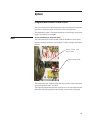
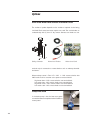
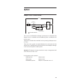
®
Marley CoolBoost Fan and Pump Control Panel System
User Manual 09-1368
Introduction
NEMA 4X fiberglass outdoor enclosure with the following features:
• Hinged and lockable outer door
• Swing-out dead front inner door
• Corrosion resistant enclosure
• Operators mounted on inner door
Electrical Components
• External disconnect handle with padlocking provisions to meet lockout,
tag-out safety requirements
• Main circuit breaker with thermal and magnetic overload protection
• Solid-state temperature controller with two-line display showing setpoint and coil fluid temperature
• RTD with dry well
• Fan and pump starter
• Pilot lights
• Status contacts
• Wiring diagram laminated and mounted on inside door
• Built to UL508 and CUL508 safety requirements
Options:
2
• Single Point Power Connection
• Integrated basin heater controls
• Integrated water level controls
• Integrated damper power circuit
• VFD feeder breaker if fan is controlled with remote VFD
• Factory installed and wired on selected products
Introduction
These instructions are intended to assure that field connections are completed
properly and the control system operates for the maximum time possible. Since
product warranty may depend on your actions, please read these instructions
thoroughly prior to operation.
If you have questions about the operation and/or maintenance of this control
system and you do not find the answers in this manual, please contact your
Marley sales representative.
Warning
Hazard of electrical shock or burn. Be sure to turn off power to the
panel before servicing. If working on equipment out of site of panel
disconnect, lockout using standard lockout procedure.
Safety First
®
The Marley control system uses UL listed components installed in accordance
with the National Electric Code. The location of the cooling product and field
installation of the control system can affect the safety of those responsible
for installing, operating or maintaining the tower and controls. However, since
SPX Cooling Technologies does not control the fluid cooler location, or field
installation, we cannot be responsible for addressing safety issues that are
affected by these items.
Warning
The following safety issues should be addressed by those responsible
for installation, maintenance or repair of the tower and controls:
• Access to and from the control panel (including the customer
supplied main disconnect/branch circuit protection.)
• Proper grounding of electrical control circuits.
• Sizing and protection of branch circuits feeding the control
panel.
• Qualification of persons who will install, maintain and service
the electrical equipment.
These are only some of the safety issues that may arise in the design and
installation process. SPX Cooling Technologies strongly recommends that
you consult a safety engineer to be sure that all safety considerations have
been addressed.
Warning
Other safety issues are addressed in literature supplied with your
cooling product. You should closely review the literature prior to
installing, maintaining or repairing your cooling product.
3
Installation
The control panel may be mounted indoors or outdoors. Inside the control
panel are steel mounting feet which may be bolted into the enclosure mounting
holes and extend beyond the outside dimensions of the enclosure.
Locate all incoming and outgoing terminations in the bottom of the enclosure
to avoid water entering the control panel.
Install the Marley RTD in the discharge piping coming from the coil discharge.
Note
Do not install the RTD in the fluid cooler coil piping.
Locate the RTD close to the fluid cooler to avoid building in a delayed reaction
time. The dry well is furnished with a ½” NPT stainless steel fitting. Insertion
length is 2½” or less into the pipe depending on pipe fitting. Locate the dry
well in the side or bottom of the pipe to assure the tip of the dry well is covered
with fluid at all times.
Run control wiring from the RTD to terminal points located in the control panel.
Belden # 8770 wire is recommended.
RTD SENSOR
FLUID RETURN
LINE
1/2" NPT COUPLING
THERMOWELL
SENSOR WIRING
RTD
Temperature
Controller–located
in CoolBoost panel
Belden #8770
3-wire plus Shield
4
Installation
Circulating Pump Circuits
The circulating pump circuit utilizes two safety circuits to protect the pump,
a low water shut off and freezing water shut off. These circuits are furnished
as standard on every fluid cooler.
A dedicated stilling chamber with one reference probe and one level probe is
furnished in the cold water basin serving as water level feedback for the low
water safety circuit. An optional second stilling chamber may be furnished
with additional level probes but services a different purpose such as water
make up and alarm. Connect the two low water probes located in the basin
stilling chamber to user terminal points in the CoolBoost control panel. Marley
probes are furnished with 20'-0" leads which may be lengthened by splicing
18 gauge control wiring. Refer to the wiring diagram in the CoolBoost control
panel for connection points.
Stilling Chamber
Water Level Probes
Water Level Card
5
Installation
For the freeze safety circuit run two 18 gauge control wires from the thermostat
located on the fluid cooler side casing to user terminal points in the CoolBoost
control panel. The thermostat has two sets of terminal points. Use either the
left or right two points oriented in a vertical column.
Note
Adjust the temperature range so the red arrow on the left points to
35˚F as shown below.
The thermostat, provided with this system, requires adjustment.
Remove the inner most brass fitting located on the thermostat
enclosure to gain access to the adjusting screw. Adjust cut-out set
point temperature to 45˚F. This automatically sets the cut-in point
at 35˚F.
THERMOSTAT
PROBE
Thermostat Installed on Casing
Thermostat and Probe
Use this
Adjustment Screw
Set at 35°F
THERMOSTAT
PROBE
Thermostat Probe Installation
6
Thermostat
N.O. Contact
Operation
Main circuit breaker: Operating handle for the main breaker is located behind
the outer door which is pad-lockable for lock out/tag out.
Rotating the handle to the OFF position turns power off to the panel.
Rotating the handle to the ON position provides power to the control panel.
If servicing the panel hot (door open and main breaker in energized position)
be sure to align the keyed slot on back of the operating handle with the key
on the main breaker shaft before closing the door.
Power “ON” light: A pilot light indicates the main disconnect is on and the
control panel is powered.
Fan circuit:
Full voltage across the line starter.
Bi-metal type motor overload protection.
H-O-A selector switch control.
Solid state PI type temperature controller.
Dual display on the Pi temperature controller shows process fluid
(PV) and set point (SP) temperatures.
Set point temperature is adjustable from the controller’s keypad by
pressing the up and down arrows on the keypad.
RTD with dry well used to sense temperature for the temperature
controller.
User terminal points for vibration switch shut down circuit.
Fan Operation: Program the temperature controller with the required set
point value. 85°F is the factory default and may be field adjusted. On the Love
Controls series 16B controller press UP or DOWN arrow button to adjust
the set point temperature. The display will revert to the normal screen within
30 seconds.
HAND position - With the selector switch in HAND the fan motor will energize and will run at a constant full speed. The HAND position may be used
to bump the motor to check fan rotation or manual motor operation.
OFF position – Fan motor will be de-energized
AUTO position – In AUTO position the temperature controller controls
the ON and OFF cycling of the fan motor. The temperature controller
compares the error difference between the discharge fluid measurement
by the RTD and the set point value making the decision to turn the fan
motor on or off.
7
Operation
Temperature Controller Information
Solid State Temperature Control for one and two speed control panels
Temperature Controller: Love Control cat # 16B-33 controller
RTD: Marley item # D37528 RTD 3 wire PT100
Love solid state temperature controller using an RTD to measure cold water
discharge temperature providing ON-OFF starter control.
The Love 16B-33 temperature controller furnished in this control panel has
been preprogrammed as follows.
Marley CoolBoost Programming Parameters:
Single speed motor programming:
Primary menu:
SV = 85Push (enter) for 3 sec.
CnPt = Pt (enter) push index
tPun = F (enter) push index
tP-h = 300 (enter) push index
tP-L = 0 (enter) push index
CtrL = onoF (enter) push index
S-HC = Cool (enter) push index
ALA1 = 6 (enter) push index
ALA2 = 7 (enter) push index
ALA3 = 11 (enter) push index
SALA = oFF (enter) push index
CosH = oFF
Ignore everything below CosH
Push (enter) twice
Cts = 5.0 (enter) push index
tPoF = 0.0 (enter) push index
Push (enter)
Push index
8
Operation
r-S = rUn (enter) push index
SP =0 (enter) push index
AL1H = 110 (enter) push index
AL2L = 43 (enter) push index
AL3H = 13 (enter) push index
AL3L = 8 (enter) push index
LoC = LoC2 Push (enter)
These settings yield the following operation:
Single speed motor programming:
Low speed ON at 90°F (Setpt 1 / Output A)
Low speed OFF at 85°F (Setpt 1 / Output A)
Alarm ON above 110°F and below 43(AL1)
Note: Out put #2 is programmed but not used for 1S1W motor.
Two speed motor programming:
Low speed ON at 90°F (Setpt 1 / Output A)
High speed ON at 99°F (Setpt 2 / Output B)
High speed OFF at 93°F (Setpt 2 / Output B)
Low speed OFF at 85°F (Setpt 1 / Output A)
Alarm ON above 110°F and below 43 (AL1)
Note
Setpoint 2 is a deviation of Setpoint 1, so the actual ON and OFF
points will change when Setpoint 1 is changed.
9
Operation
Pump Operation
Standard operation of the pump is by manual control only, using a two-position
selector switch located on the door. A removable “run enable” jumper is
provided so customer may take control of cycling the pump. See the control
panel wiring diagram.
Caution
Cycling the pump on and off for temperature control could cause
scaling on the coils and is not recommended.
OFF-ON Selector Switch
• OFF position – pump motor is off.
•O
N position – pump motor will run constantly unless a safety circuit is
activated.
If the water temperature in the cold water basin drops to 35°F a N.O. contact
from the remote thermostat will close and latch-in a relay, which in turn shuts
off the circulating pump. This is a safety circuit to prevent pumping freezing
water. To reset this circuit, press the reset button on the door. The circuit can
be only reset once the cold water basin temperature rises above 45°F.
If the basin water drops to a dangerously low level, the water level card contact
will close and also energize the latch-in relay shutting the circulating pump
off. This is a safety circuit preventing the pump from running dry. To reset this
circuit, press the reset button on the door. The circuit can only be reset if the
water in the basin has risen to an acceptable operating level.
10
Options
Integrated Basin Heater Control Circuit
This circuit monitors the water temperature in the cold water basin via a probe
type sensor mounted through the side wall of the cold water basin.
The temperature probe is furnished with 22 feet of lead length. Longer lead
lengths up to 99 feet are available.
Note
Do not add wiring to the probe lead.
The solid state control card is located inside the CoolBoost control panel.
A power contactor inside the control panel is used to energize the heating
element.
Sensor Probe with
22 foot lead
Basin Heater Card
The temperature card and basin heater element maintains water temperature
in the basin between 40° F and 45° F.
The temperature probe includes a low water cut off circuit. If the water level falls
below the temperature probe the basin heater contactor will not energize.
11
Options
Solid State Water Level Control and Alarm Circuit
The number of probes depends on the number of optional circuits being
furnished. Each water level event requires one card. The card includes an
on-board relay with (1) form “C” dry contact. Contacts are wired to a user
Stilling Chamber
Water Level Probes
Water Level Card
terminal strip for connection to remote devices such as makeup solenoids
and alarms.
Water make-up control – Form “C” 1- N.O. 1 – N.C. contact wired to 120
VAC fused circuit for customer use to power a remote solenoid.
High water alarm - N.O. contact wired to user terminal block
Low water alarm - N.O. contact wired to user terminal block
High water cutoff – N.C. contact wired to user terminal block
Low water cutoff - N.C. contact wired to user terminal block
Pump Heat Trace
If circulation pump is has the heat trace option
connect the heat trace tape back to the CoolBoost
control panel.
12
Options
Damper “Local” Control Circuit
120VAC
CLOSE
OPEN
AUTO
DAMPER
MOTOR
FUSE
OPEN
XOO
CLOSED
OXO
OOX
M1-2
M1-3
FAN CONTACTOR
AUXILLARY CONTACTS
CUSTOMER CONNECTION
This circuit is furnished when a damper control option is ordered and the
damper circuit is controlled from the CoolBoost panel in coordination with
the fan starter.
The panel is furnished with a 120 VAC circuit for powering the damper actuator motor.
Three wires and a ground are required between the control panel and the
damper motor. 120 VAC power for the actuator motor on the damper is brought
out to user terminal points inside the panel.
Operation: The damper will open when the fan motor is energized and will
close when the fan motor is off.
H-O-A selector switch operation:
HAND position: Damper opens
OFF position:
Damper closes
AUTOMATIC position:
Damper is closed when fan is off
13
14
Typical Schematic Showing Options
15
11
10
9
8
6
7
5
4
3
2
1
5
5
FU 6
7
21
19
G1
COM
120
OFF
CB
AMPS
HAND
FNM 1 1/4
GROUND
TEMPERATURE /
LEVEL PROBE IN
WATER BASIN
5
VIB. SW.
3
INCOMING LINE POWER
VOLTS
PHASE
HERTZ
SUPPLY
8
L1
G2
5A
16
22
20
FU 4
(97)
T2
T1
SH
C1
25
H2
X2
DH
(8)
(2)
P1HT
120 VOLTS
FNQR 2
C2
C1
C2
F1
17
(12)
TEMPERATURE
CONTROLLER
(7)
(1)
H4
(11)
11
50W STRIP HEATER
NC
NO
N
(98)
F1 LOW ALARM
10
PURPLE JUMPER
H3
300 VA
480 VOLTS
REMOTE ENABLE
FU 5
X1
H1
FU 1
FNM 1 1/4
FNM 1
FU 3
FNM 4
FNQR 2
INDEECO HEATER
CONTROL CARD
OOX
OOX
XOO
XOO
AUTO
L3
L2
FU 2
29
7
9
30
F1
B
(A1)
(13)
R
C1
CR3
10
DAMPER HEATER
PUMP 1 HEAT TRACING
(SELF REGULATING)
(A2)
(14)
3
3
B
(95)
OL
(96)
6
6
6
120V FOR
CUSTOMER USE
BASIN HEATER
ON LIGHT
BASIN HEATER
CONTACTOR
BASIN HEATER
CONTROLLER
FAN O.L. TRIP
RELAY
FAN O.L. TRIP
TEMPERATURE
CONTROLLER
FAN STARTER
DAMPER HEATER
PUMP 1 HEAT
TRACE
5
FU 7
43
OFF
Wht
Red
Red
RTD
CONNECTION
(5)
(10)
4
S
1
3
CBL1
(5)
(4)
36
49
45
40
NC
NO
COM
N
L
RESET
F1
F1
47
10
PURPLE JUMPER
CIRC. PUMP CUT-OFF
RELAY
LLC24A2F50N
"A"
CARD
TEMPERATURE
CONTROLLER
CONNECTION
WHT (3)
RED
BLK
OOX
OXO
XOO
(2)
CR2-2
COM
CLOSE
AUTO
46 OPEN
(98)
44
39
BLUE WIRE
LO
HI
LOW TEMP ALARM
BLUE WIRE
P1 ALARM
OX
OX
ON
(97)
FNM 1 1/4
5
13B
19B
(9)
CR2-1
3
JOHNSON CONTROLS
Continued On Page 2
R
(14)
CR5
B
P1
CLOSED
OPEN
B
CR6
(13)
(A1)
42
(13)
DAMPER
CONTROL
(14)
(A2)
(3)
38
(14)
(95)
(96)
P1 OL
CR2
(7)
6
DAMPER CONTROL
DAMPER OPEN
LIGHT
PUMP 1
OVERLOAD
TRIP LIGHT
PUMP 1 OVERLOAD
TRIP RELAY
PUMP 1 RUNNING
LIGHT
WATER PUMP 1
CIRC. PUMP CUT-OFF
PUMP SAFETY CIRCUT
SHUT DOWN RELAY
PUMP SAFETY CIRCUT
SHUT DOWN LIGHT
2 SEC DELAY FAULT
TIMER
Marley CoolBoost Fan and Pump Panel
Options: Basin Heater Control Ciruit
48
(13)
41
(1)
R
TR2-1
TR2
Typical wiring diagram. Not to be used for construction.
See as built wiring diagrams for specific projects.
36
37
(2)
6
16
24
23
F1
GROUND
LOAD
POWER
TERMINAL
TORQUE
12.39 IN/LBS.
CONTINUED FROM
VOLTS
PAGE 1
PHASE
HERTZ
SUPPLY
F1
P1
T2
T3
8
480 VOLTS
480 VOLTS
6
P1
5
GROUND
20 AMPS.
T1N020TL
56
C1
5
LOAD
POWER
TERMINAL
TORQUE
12.39 IN/LBS.
C1
55
FNQR 8
Set high and low overload amperage to motor nameplate.
Remove purple jumper when adding heater cut off.
Incoming power wire rating: 60 degrees celcius.
Field wire: 16 AWG.
Remove purple jumper when remote enable is used.
C1 & C2 connects to thermal cut off basin heater element.
6
7
8
9
10
11
Jumper must be removed when vibration switch is used.
5
Field wiring by others. USE COPPER WIRE ONLY.
Remote located equipment
4
( ) Indicates actual markings on device
3
Terminal point number on terminal block
2
1
Note:
CANDO Control Panel
Two Speed, One Winding, Three Phase
7.6 FLA
29.5 FLA
5 HP
T1
OVERLOAD RELAY
P1
PUMP MOTOR #1
5
GROUND
LOAD
POWER
TERMINAL
TORQUE
12.39 IN/LBS.
54
P1
25 HP
8
6
F1
53
FAN MOTOR #1
T3
L3
MOTOR
T2
L1
L2
MOTOR
T1
OVERLOAD RELAY
F1
CB
AMPS
FNQR 8
FU 9
C1
480 VOLTS
19 FLA
6 KW
Heater Element
C1
FNQR 8
FU 10
FU 8
C1
(8)
(5)
(5)
(9)
(5)
DAMPER OPEN
STATUS CONTACT
CR6-1
63
64
(9)
PUMP 1 O.L.
STATUS CONTACT
CR5-1
62
61
(9)
FAN O.L.
STATUS CONTACT
CR3-1
60
59
(12)
PUMP SAFETY CUT-OFF
STATUS CONTACT
CR2-4
58
57
Marley CoolBoost Fan and Pump Panel
Optional Basin Heater Control Cirucit
Typical wiring diagram. Not to be used for construction.
See as built wiring diagrams for specific projects.
Optional Basin Heater
Power Circuit
9
FAN LOW OVERLOAD
FAN REMOTE ENABLE
VIBRATION SWITCH
JUMPER
C1-C2 THERMAL CUT OFF
C1-C2 THERMAL CUT OFF
RTD SHIELD
RTD CONTACT
RTD CONTACT
RTD CONTACT
HEAT TRACE HOT WIRE
DAMPER HEATER HOT WIRE
63-64 DAMPER OPEN DRY CONTACT
63-64 DAMPER OPEN DRY CONTACT
61-62 PUMP 1 O.L. DRY CONTACT
61-62 PUMP 1 O.L. DRY CONTACT
59-60 FAN O.L. DRY CONTACT
59-60 FAN O.L. DRY CONTACT
57-58 PUMP SAFETY DRY CONTACT
57-58 PUMP SAFETY DRY CONTACT
55-56 HEATER CONTACTOR ON
55-56 HEATER CONTACTOR ON
53-54 PUMP 1 CONTACTOR ON
53-54 PUMP 1 CONTACTOR ON
43-44 PUMP 1 SEL. SW. ON
43-44 PUMP 1 SEL. SW. ON
PUMP 1 REMOTE ENABLE
PUMP 1 REMOTE ENABLE
HEATER REMOTE ENABLE
HEATER REMOTE ENABLE
FAN REMOTE ENABLE
23-24 FAN RUNNING
23-24 FAN RUNNING
21-22 FAN IN AUTO DRY CONTACT
21-22 FAN IN AUTO DRY CONTACT
19-20 FAN IN HAND DRY CONTACT
C2
C1
S
4
3
1
P1HT
DH
64
63
62
61
60
59
58
57
56
55
54
53
49
48
47
46
45
44
43
42
41
40
39
37
36
30
29
25
24
23
22
21
20
19
17
16
12
10
9
7
6
6
6
5
5
10
REMOVE
JUMPER
WHEN
USING
REMOTE
ENABLE
FACTORY
JUMPERS
TERMINAL STRIP
19-20 FAN IN HAND DRY CONTACT
FIELD WIRE TERMINAL
POINT
TORQUE:18IN./LBS.
5
120V 50VA
SUPPLY FOR
CUSTOMER USE
Troubleshooting
Trouble
Cause
Remedy
Main disconnect OFF
Make sure main disconnect switch is in the ON position
Blown fuse(s)
Check primary and secondary fuses for the control supply voltage located
on top of the control power transformer. Check incoming Line Voltage fuses.
(replace fuses as necessary.)
Vibration switch, external safeties, or run
permission contacts are inhibiting closure of
the fan motor contactor (open circuit between
terminals 5 and 7).
Reset vibration limit switch and/or verify customer start inhibit does not exist.
(e.g. Building automation, Emergency Stop)
Fan motor OL (Over-Load) tripped.
Verify the OLs sized correctly. (heater size or dial setting.) Reset motor OL.
To reset OLs, sufficient time must elapse to cool the bi-metal OL heaters.*
Set point temperature programmed into the
temperature controller is higher then the actual
temperature of the fluid in the coil therefore there
is no call for cooling.
Lower the set point value in the controller
Temperature controller indicates an alarm.
(Amber AL)**
Program controller to an appropriate alarm setting.** Then, press reset button
located on the front door of the control panel.
Temperature controller is not functioning
properly.
First, verify the controller is not in a fault condition, that the setpoint of the
controller is accurately programmed, and the fluid being cooled has reached
the temperature required to run the fan motors. Then using a voltage meter,
check for 120VAC being present between terminals 16 and 6. Then check
for 120VAC between terminals 9 and 6. If voltage exists between 16 and 6
and not between 9 and 6 call for assistance to replace the PI controller.
Pump motor OL. (Over-Load) tripped.
Verify the OLs sized correctly. (dial setting) Reset motor OL. To reset OLs,
sufficient time must elapse to cool the bi-metal OL heaters.**
Tripped circuit breaker for pump motor supply
voltage.
Reset the circuit breaker
The pump alarm light has energized.
Make appropriate adjustments to insure basin water level meets requirements.
Once basin water has reached its required level press the alarm reset located
on the front of the control panel.
The pump alarm light has energized.
Make appropriate adjustments to insure basin water temperature meets
requirements. Once basin water has reached its required temperature press
the alarm reset located on the front of the control panel.
Water temperature is above 45°F.
The water temperature must drop to 45°F before the basin heater circuit will
energize the heater contactor. Once the contactor is energized, the heater(s)
will remain on until the temperature is above 50°F.
The fan motor is running.
The heater contactor circuit is designed not to energize the heater elements
while the fan motor is running.
Blown fuse(s).
If the fan motor is running and the basin cold water temperature is below
45°F. Check the voltage supply fuses to the heating elements. (replace fuses
as necessary.)
Heater Control circuit card or heater elements
not functioning correctly.
If the fan motor is running and the basin cold water temperature is below
45°F. Call for troubleshooting assistance in determining if replacement of
heater control card or heater element is necessary.
Integrated Damper Control
Option
Damper switch will not manually open
or close the damper.
Blown fuse.
If by switching the OPEN, OFF, AUTO selector between OPEN and OFF does
not change the position of the damper. Check FU3 fuse which supplies the
damper control circuit. (replace blown fuse.)
Integrated Damper Control
Option
Damper will open and close manually
but will not open in AUTO.
Fan motor is not running.
To check AUTO operation of the damper control, the fan motor must be running.
When fan is running, dampers should open. When fan is off, dampers should
close. Check for correct wiring at the damper logic contacts.
Fan motor ALARM LIGHTS
Fan motor OL (Over-Load) tripped.
Verify the OLs sized correctly. (dial setting.) Reset motor OL. To reset OLs,
sufficient time must elapse to cool the bi-metal OL heaters.*
Pump motor ALARM LIGHTS
Pump motor OL (Over-Load) tripped.
Verify the OLs sized correctly. (dial setting.) Reset motor OL. To reset OLs,
sufficient time must elapse to cool the bi-metal OL heaters.*
Control Power
No power ON light
Fan Motor
Power Light is ON but the fan
motor(s) will not operate in the HAND
position.
Fan Motor
Power Light is ON but the fan
motor(s) will not operate in the AUTO
position only.
Pump Motor
When the pump switch is turned to
the ON position, the circulating pump
motor will not run.
Integrated Basin Heater Control
Option
Basin heater control is not turning on.
Heater element(s) in the cold water
basin are not heating the water.
* Over Load tripping is caused by excessive motor current. Frequent and continued tripping indicates possible motor and or mechanical operation problems. Troubleshooting
procedures must be performed on these associated components to determine the cause of the over current condition.
** The alarm setting on the temperature controller has been factory preset at 40°F. A 5° differential exists between the when alarm is activated and when a reset
is accepted. For example if the programmed alarm temperature is reached, the fluid temperature would need to rise an additional 5° in order to reset the controller
(if set at 40°, it must rise above 45°).
17
SPX COOLING TECHNOLOGIES, INC.
7401 WEST 129 STREET | OVERLAND PARK, KANSAS 66213 UNITED STATES | 913 664 7400 | [email protected] | spxcooling.com
In the interest of technological progress, all products are subject to design and/or material change without notice.
©2011 SPX | Printed in USA
Manual 09-1368