1
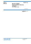
User’s
Manual
Model RC400G
Residual Chlorine Analyzer
[Style: S3]
IM 12F4A1-01E
IM 12F4A1-01E
8th Edition
i
Introduction
The RC400G Residual Chlorine Analyzer is a process analyzer for continuous measurement of
free chlorine concentration and residual chlorine contained in chlorine-treated water.
1. Confirmation of Specifications
The RC400G comprises Tap Water type (RC400G-1), Raw Water type (RC400G-2) and Treated
Water type (RC400G-3).
When the RC400G has been delivered to your location, carefully unpack and check the equipment for any transportation damage, and ensure that the equipment is of the correct specifications as ordered. Confirm this by the model code indicated on the nameplate or the package tag
referring to Chapter 2 of this manual.
NOTE
1. Unpack the equipment at a location close to its installation site.
2. Locate on power to read to version number of ROM loaded on the equipment. Then, follow
the procedures as instructed in item (10) of subsection 5.3.3 after completion of the installation work, such as wiring.
2. Caution for Transfer and Storage
Observe the following notices so as not to damage the RC400G on transfer and storage.
• When transferring the RC400G to its installation site or elsewhere, prevent the equipment
from receiving strong impact, and exercise care to minimize the vibration received.
CAUTION
Carry the RC400G in the same attitude as it will be installed. the RC400G weight exceeds 60 kg.
(For details, see subsection 2.1.1.)
• For storing the RC400G, select a place where the ambient temperature is in the range of
from -30 to 70 °C. Humidity must be of a level that does not result in dew condensation.
Exposure to corrosive gases or water splash must be avoided as well.
Media No. IM 12F4A1-01E
8th Edition : Aug, 2014 (YK)
All Rights Reserved Copyright © 1992, Yokogawa Electric Corporation
IM 12F4A1-01E
8th Edition : Aug. 2014
ii
3. Content of User’s Manual
This user’s manual fully describes the handling of the RC400G, including installation, wiring,
operation, inspection/maintenance and so forth.
Operating principle and specifications are also shown to help in the understanding of the
RC400G Residual Chlorine Analyzer.
To achieve full performance of this equipment, the user id recommended to peruse this manual
before handling the equipment.
This manual also introduces various peripheral equipment prepared by Yokogawa such as the
RC401G Reagent Tank which is used in combination with the RC400G analyzer.
Note: This manual does not describe any equipment or attachments that are supplied on special order.
CAUTION
If this manual is used during the planning stage in advance of equipment order placement,
please be note that the content of this manual is subject to change without prior notice for product
improvement or other reasons.
When the manual is revised, the edition number or version number in the cover of the manual
changes.
u Safety Precautions
n Safety, Protection, and Modification of the Product
• In order to protect the system controlled by the product and the product itself and ensure
safe operation, observe the safety precautions described in this user’s manual. We assume
no liability for safety if users fail to observe these instructions when operating the product.
• If this instrument is used in a manner not specified in this user’s manual, the protection
provided by this instrument may be impaired.
• If any protection or safety circuit is required for the system controlled by the product or for
the product itself, prepare it separately.
• Be sure to use the spare parts approved by Yokogawa Electric Corporation (hereafter simply
referred to as YOKOGAWA) when replacing parts or consumables.
• Modification of the product is strictly prohibited.
• The following symbols are used in the product and user’s manual to indicate that there are
precautions for safety:
IM 12F4A1-01E
8th Edition : Aug. 2014
iii
n Symbol Marks
Throughout this user’s manual, you will find several different types of symbols are used to identify
different sections of text. This section describes these icons.
CAUTION
Identifies instructions that must be observed in order to avoid physical injury and electric
shock or death of the operator.
WARNING
Identifies instructions that must be observed in order to prevent the software or hardware
from being damaged or the system from becoming faulty.
NOTE
Identifies information required to understand operations or functions.
n Notes on Handling User’s Manuals
• Please hand over the user’s manuals to your end users so that they can keep the user’s
manuals on hand for convenient reference.
• Please read the information thoroughly before using the product.
• The purpose of these user’s manuals is not to warrant that the product is well suited to any
particular purpose but rather to describe the functional details of the product.
• No part of the user’s manuals may be transferred or reproduced without prior written consent from YOKOGAWA.
• YOKOGAWA reserves the right to make improvements in the user’s manuals and product at
any time, without notice or obligation.
• If you have any questions, or you find mistakes or omissions in the user’s manuals, please
contact our sales representative or your local distributor.
n Warning and Disclaimer
The product is provided on an “as is” basis. YOKOGAWA shall have neither liability nor responsibility to any person or entity with respect to any direct or indirect loss or damage arising from
using the product or any defect of the product that YOKOGAWA can not predict in advance.
IM 12F4A1-01E
8th Edition : Aug. 2014
iv
u After-sales Warranty
n Do not modify the product.
n During the warranty period, for repair under warranty carry consult
local sales representative or service office. Yokogawa will replace or
repair any damaged parts. Before consulting a product for repair under warranty, provide us with the model name and serial number and a
description of the problem. Any diagrams or data explaining the problem would also be appreciated.
l If we replace the product with a new one, we won’t provide you with a repair report.
l Yokogawa warrants the product for the period stated in the pre-purchase quotation
Yokogawa shall conduct defined warranty service based on its standard. When the customer site is located outside of the service area, a fee for dispatching the maintenance engineer
will be charged to the customer.
n In the following cases, customer will be charged repair fee regardless
of warranty period.
• Failure of components which are out of scope of warranty stated in instruction manual.
• Failure caused by usage of software, hardware or auxiliary equipment, which Yokogawa
Electric did not supply.
• Failure due to improper or insufficient maintenance by user.
• Failure due to modification, misuse or outside-of-specifications operation which Yokogawa
does not authorize.
• Failure due to power supply (voltage, frequency) being outside specifications or abnormal.
• Failure caused by any usage out of scope of recommended usage.
• Any damage from fire, earthquake, storms and floods, lightning, disturbances, riots, warfare,
radiation and other natural changes.
n Yokogawa does not warrant conformance with the specific application
at the user site. Yokogawa will not bear direct/indirect responsibility
for damage due to a specific application.
n Yokogawa Electric will not bear responsibility when the user configures the product into systems or resells the product.
n Maintenance service and supplying repair parts will be covered for five
years after the production ends. For repair for this product, please
contact the nearest sales office described in this instruction manual.
IM 12F4A1-01E
8th Edition : Aug. 2014
Toc-1
Model RC400G
Residual Chlorine Analyzer
[Style: S3]
IM 12F4A1-01E 8th Edition
CONTENTS
Introduction...............................................................................................................i
u Safety Precautions..............................................................................................ii
u After-sales Warranty...........................................................................................iv
1.Outline........................................................................................................ 1-1
2.
1.1
RC400G Residual Chlorine Analyzer Configuration...................................... 1-2
1.2
Operating Principle of RC400G Residual Chlorine Analyzer........................ 1-3
Specifications............................................................................................ 2-1
2.1
RC400G Residual Chlorine Analyzer............................................................... 2-1
2.1.1
Standard specifications....................................................................... 2-1
2.1.2Characteristics.................................................................................... 2-5
2.1.3Accessories......................................................................................... 2-5
2.2
2.1.4
Product model and suffix codes.......................................................... 2-6
2.1.5
Flow diagrams and outline drawings.................................................. 2-8
RC401G Reagent Tank.................................................................................... 2-11
2.2.1
Standard specifications..................................................................... 2-11
2.2.2
Product model and suffix codes........................................................ 2-12
2.2.3Accessories....................................................................................... 2-12
2.2.4
3.
Outline drawings............................................................................... 2-12
Installation, Tubing and Wiring................................................................ 3-1
3.1Installation.......................................................................................................... 3-1
3.1.1Location............................................................................................... 3-1
3.1.2Installation........................................................................................... 3-1
3.2
3.3
Tubing.................................................................................................................. 3-1
3.2.1
Sample Water Tubing......................................................................... 3-6
3.2.2
Reagent Tubing................................................................................... 3-6
3.2.3
Cleaning Water Tubing....................................................................... 3-6
3.2.4
Drain Tubing........................................................................................ 3-7
3.2.5
Purge Air Tubing................................................................................. 3-7
3.2.6
Standard Solution Tubing................................................................... 3-7
3.2.7
Automatic Zero Calibration Tubing..................................................... 3-7
Wiring.................................................................................................................. 3-8
3.3.1
Wiring for Power Supply and Grounding.......................................... 3-13
3.3.2
Wiring for Analog Output Signals...................................................... 3-14
IM 12F4A1-01E
8th Edition : Aug. 2014
Toc-2
4.
3.3.3
Wiring for Contact Input (<remote> Range Switching)..................... 3-14
3.3.4
Wiring for Contact Output................................................................. 3-15
Operation.................................................................................................... 4-1
4.1
Component Identification and Function......................................................... 4-1
4.2
Preparation for Operation................................................................................. 4-4
4.3
4.2.1
Reagent Preparation........................................................................... 4-4
4.2.2
Filling Bead Case with Electrode Polishing Glass Beads................... 4-5
4.2.3
Checking the Sand in the Sand Filter................................................. 4-5
Startup................................................................................................................. 4-6
4.3.1
Confirming Tubing and Wiring Implementation.................................. 4-6
4.3.2
Feeding Sample Water and Adjusting Flow........................................ 4-6
4.3.3
Supplying Cleaning Water.................................................................. 4-6
4.3.4
Turning on Power................................................................................ 4-6
4.3.5 Confirming Sample Water Metering Pump Delivery Flow..................... 4-6
4.3.6
Confirming Reagent Metering Pump Delivery Flow........................... 4-7
4.3.7
Confirming Indicator Electrode Operation.......................................... 4-8
4.3.8
Confirming Cleaning Solenoid Valve Operation and Adjusting Ball Valve
Opening.............................................................................................. 4-8
4.3.9
Purging Air Supplying.......................................................................... 4-9
4.3.10
Polishing Indicator Electrode.............................................................. 4-9
4.3.11
Filling the Zero Filter Case and Running-in Operation..................... 4-10
4.3.12
Output Range Setting....................................................................... 4-11
4.3.13Calibration......................................................................................... 4-11
4.4
5.
Converter Operation................................................................................. 5-1
5.1
Component Identification and Functions on the Control Panel................... 5-1
5.2
Operation Modes and Functions...................................................................... 5-2
5.3
6.
Operation.......................................................................................................... 4-11
5.2.1
Function Codes and Their Description in <MEAS.> Mode................. 5-3
5.2.2
Function Codes and Their Description in <MAINT.> Mode................ 5-4
5.2.3
Function Codes and Their Description in <PROGRAM.1> Mode...... 5-4
5.2.4
Function Codes and Their Description in <PROGRAM.2> Mode...... 5-6
Key Operation..................................................................................................... 5-7
5.3.1
Operation Key Types and Functions.................................................. 5-7
5.3.2
Key Operation in <MEAS.> Mode...................................................... 5-9
5.3.3
Key Operation in <MAINT.> Mode.................................................... 5-11
5.3.4
Key Operations in <PROGRAM.1> Mode........................................ 5-21
5.3.5
Key Operation in <PROGRAM.2> Mode.......................................... 5-32
Converter Operating Functions............................................................... 6-1
6.1
<failure> Detecting Operation.......................................................................... 6-1
6.1.1
Concentration Range Exceeded (Err11)............................................ 6-1
6.1.2
Sample Temperature Failure (Err12, Err24)....................................... 6-1
6.1.3
Out-of-Sample in the Measuring Tank (Err13).................................... 6-1
IM 12F4A1-01E
8th Edition : Aug. 2014
Toc-3
6.1.4
Converter Failure (Err14, Err15, Err16, and Err17)............................ 6-3
6.1.5Concentration Upper Limit Setpoint Exceeded (Err25)...................... 6-3
7.
6.2
Analog Output Signal........................................................................................ 6-4
6.3
Contact Output................................................................................................... 6-4
6.4
Contact Input...................................................................................................... 6-4
6.5
Default Status When Mode Change................................................................. 6-5
Calibration.................................................................................................. 7-1
7.1
Running-in Operation........................................................................................ 7-1
7.2
Zero Calibration.................................................................................................. 7-1
7.3
8.
Zero Calibration Using Open Input Circuit Method............................. 7-1
7.2.2
Zero Calibration Using Chlorine-Free Water ..................................... 7-2
7.2.3
Automatic Zero Calibration Using Chlorine-Free Water .................... 7-3
Span Calibration................................................................................................ 7-5
Maintenance............................................................................................... 8-1
8.1
Inspection/Maintenance Items and Intervals.................................................. 8-1
8.2
Reagent Replenishment.................................................................................... 8-1
8.3
Indicator Electrode Polishing........................................................................... 8-1
8.4
Glass Beads and Measuring Tank Cleaning................................................... 8-2
8.5
Calibration.......................................................................................................... 8-3
8.6
Metering Pump Driving Section Oiling............................................................ 8-3
8.7
Replacement of “Bellofram” and Valve Sheet in Metering Pump................ 8-3
8.7.1
“Bellofram” Replacement.................................................................... 8-4
8.7.2
Valve Sheet Replacement.................................................................. 8-5
8.8
Metering Pump Delivery Flow Rate Confirmation and Adjustment............. 8-5
8.9
Inspection and Maintenance of Sand Filters.................................................. 8-6
8.10
9.
7.2.1
8.9.1
Inspection of Sand Filter Surface........................................................ 8-6
8.9.2
Checking the Sand Volume in Sand Filters........................................ 8-6
8.9.3
Checking the Discoloration of Sand in Sand Filters........................... 8-7
8.9.4
Filter Replacement.............................................................................. 8-7
Inspection of Electrode Mechanism Block and Replacement of Damaged Parts....8-8
8.10.1
Inspection, Maintenance and Replacement of Brush and Slip Ring.. 8-9
8.10.2
Inspection, Maintenance and Replacement of Drive Belt................ 8-10
8.10.3
Inspection, Maintenance and Replacement of Driven Shaft Assembly.8-11
8.10.4
Inspection, Maintenance and Replacement of Motor Assembly/Gear
Head.................................................................................................. 8-13
8.10.5
Replacement of Activated Charcoal Filter........................................ 8-14
Troubleshooting........................................................................................ 9-1
9.1
9.2
When <failure> is Indicated.............................................................................. 9-1
9.1.1
Indication of Error Message or Error Code During Operation............ 9-1
9.1.2
<FAIL> Lamp Lit.................................................................................. 9-4
Operation Failures in Measurement Without <failure> Detection................ 9-8
IM 12F4A1-01E
8th Edition : Aug. 2014
Toc-4
9.3
10.
Other Failures................................................................................................... 9-10
9.3.1
Analog Output does not Correspond to Indicated Value.................. 9-10
9.3.2
Cleaning is not Conducted Properly................................................. 9-10
9.3.3
“Remote” Range Switching does not Work...................................... 9-10
Spare Parts and Consumables.............................................................. 10-1
10.1
Spare Parts and Consumables List............................................................... 10-1
10.2
Complementary Description........................................................................... 10-2
10.2.1
Reagent (K9041TH, K9041TG, K9041TJ, K9041TQ)..................... 10-2
10.2.2
Lubricating oil (K9041RA)................................................................. 10-2
10.2.3
Polishing Powder (K9088PE)........................................................... 10-2
10.2.4
Glass Beads (K9332ZJ).................................................................... 10-2
10.2.5
Sand (K9720FZ)............................................................................... 10-2
10.2.6
Valve Sheet (K9041HC).................................................................... 10-2
10.2.7
“Bellofram” (L9819AA, L9819AB)..................................................... 10-3
10.2.8
Indicator Electrode (K9334JP).......................................................... 10-3
10.2.9
Counter Electrode (K9332MJ), for Combined Chlorine (K9332MK).10-3
10.2.10
Fuse (A1113EF, A1109EF)................................................................ 10-3
10.2.11
Brush (K9332JX) and Slip Ring (K9332JZ)...................................... 10-4
10.2.12
Driven Shaft Assembly (K9334JV)................................................... 10-4
10.2.13
Drive Belt (L9804UK)........................................................................ 10-4
10.2.14
Motor Assembly (See CMPL for Part Number)................................. 10-4
10.2.15
Gear Head (See CMPL for Part Number)......................................... 10-4
10.2.16
Activated Charcoal Filter (L9862AY)................................................ 10-4
10.2.17
Filter (K9332NN)............................................................................... 10-4
Customer Maintenance Parts List....................................... CMPL 12F04A01-03E
Customer Maintenance Parts List....................................... CMPL 12F04A01-11E
Revision Information................................................................................................i
IM 12F4A1-01E
8th Edition : Aug. 2014
1-1
<1. Outline>
1.Outline
In chlorinated tap water and industrial water, the chlorination effect can be determined by
measuring residual chlorine contact.
The RC400G Residual Chlorine Analyzer is for process use and employs rotating electrode polarography as its measuring principle.
It can be used for continuous measurement of residual chlorine composed of free available chlorine and combined available chlorine or for free available chlorine only.
The RC400G Residual Chlorine Analyzer includes “Tap Water type (Model RC400G-1)”
suitable for measurement of tap water or filtered water, “Raw Water type (Model RC400G2)” suitable for measurement of raw water and “Treated Water type (Model RC400G-3)”
suitable for measurement of treated water such as sewer water after secondary treatment
or plant waste water.
l Combined Chlorine Insensitive Version
If raw water contains large quantities of ammonia nitrogen, combined chlorine will form and remain in the reaction process even if necessary and sufficient chlorine is added at prechlorination
point. In particular, when the pH and temperature of the water are low, combined chlorine (dichloramine) remains longer and breaks down slowly.
In measurement of free available chlorine in sample water that contains a high concentration of
combined chlorine, measurement errors may occur when the previous model of residual chlorine
analyzer is used. To solve this problem the combined chlorine insensitive version should be used.
It has modified electrode and reagent composition, thereby improving sensitivity to free available
chlorine in the presence of combined chlorine. The electrode configuration, reagent composition and applied voltage have been changed, otherwise, the measurement principle, equipment,
specifications and performance remain unchanged from the previous model.
In this chapter, the operating principle and structural outline of the RC400G Residual Chlorine
Analyzer is described.
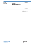
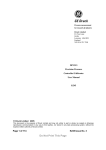
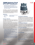
Converter
Detector
Metering pump
Front
Figure 1.1
Side
Back
F1.1E.ai
Appearance of RC400G Residual Chlorine Analyzer (RC400G-1, Tap Water type)
IM 12F4A1-01E
8th Edition : Aug. 2014
1.1
1-2
<1. Outline>
RC400G Residual Chlorine Analyzer
Configuration
The RC400G Residual Chlorine Analyzer is mainly composed of a “measuring system”, a “sampling system” and an “air tubing system”.
In addition, a “cleaning piping system” is added to raw water treated water analyzers.
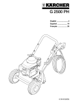
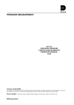
n Measuring System
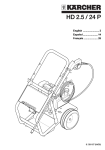
“Measuring System” mainly consists of a detector and a converter.
The detector contains a measuring tank and an electrode mechanism block. The electrode
mechanism block incorporates two electrodes, indicator electrode (gold alloy electrode) and
counter electrode (platinum electrode with built-in Pt1000 temperature sensor), and a drive assembly composed of a starting motor for rotating the indicator electrode at a constant speed, a
drive belt, etc.
The electrodes obtain diffusion currents by electrolytic reduction of iodine (for measuring total
residual chlorine) or bromine (for measuring free available chlorine) in the plateau region, which
is liberated corresponding to sample water chlorine concentration in mixed solution of sample
water with reagent fed into the measuring tank. The electrodes also serve to obtain a signal for
automatic temperature compensation of the diffusion current which varies with temperature.
The measuring tank is made of acrylic resin, and the place of indicator electrode insertion houses
the glass beads for polishing the electrode.
The measuring circuit part of the converter is housed in a sealed case of aluminium alloy together
with an operating panel and an external cable connecting the terminal board.
The measuring circuit part serves to amplify and carry out computation based on the input (diffusion current and temperature compensating signal) from the detector, and to obtain output
signals of 1 to 5 V DC or 4 to 20 mA DC, corresponding to the output range.
Drive assembly
SV1 SV2 SV3 SV4 SV5 SV6
5
MEAS
MABT
ppm
PROGRAM 1
PROGRAM 2
DATASET
,
,
.
MODE
MANUAL OPERATION
SY1
SY2
SY3
SY4
SY5
SY6
Indicator electrode
Counter
electrode
+
-
R1
R2
T1
T2
O
O1
11
U1
Operating panel
O2
12
U2
O1
U3
V1
V2
O2
P1
P2
M1
V4
J1
J2
M2
L2
L1
A1
A2
U4
V3
External cable
connecting
terminal
Measuring tank
Glass beads
F1.3.ai
Figure 1.2
Detector
Figure 1.3
Converter
n Sampling System
“Sampling System” consists primarily of sample water tubing and reagent tubing.
The system conditions the sample water and reagent fed to the measuring tank in the detector to
a specified flow rate.
The sample tubing incorporates a ball valve, a head tank (for tap water) or a sand filter (for raw or
treated water), and a metering pump.
IM 12F4A1-01E
8th Edition : Aug. 2014
1-3
<1. Outline>
The sand filter used for the raw and treated water analyzers serves to remove from sampled water flocks which contaminate electrodes and also iron and manganese ions that liberate iodine.
Another metering pump is incorporated in the reagent tubing to mix reagent from the reagent
tank with the sample water being fed to the measuring tank at a constant flow rate.
n Air Tubing System
The “air tubing system” consists of air purge tubing, etc.. The air purge tubing is provided for
preventing the components of electrode drive assembly, the converter, pump drive assembly, etc.
from corrosion due to halogen gases generated from the sample water.
When an air pump is included in the system, it supplies purging air. If no air pump is attached,
connect the system through a regulating valve to a clean and dry air source like instrument air.
n Cleaning Tubing System
The cleaning tubing system added to the raw treated water analyzers functions to clean filter
sand in the sand filter, the measuring tank and glass beads, and to remove and drain flocks.
Cleaning is automatically carried out by opening and closing the solenoid valve in cleaning water
tubing with sequence signals from the converter. The cleaning water tubing is also provided with
a regulating valve to adjust the cleaning water pressure.
n Automatic Zero Calibration Tubing System
The residual chlorine analyzer with automatic zero calibration performs zero calibration using an
activated charcoal filter. In the automatic zero calibration, the solenoid valve SV6 is opened and
closed by a sequence signal from the converter.
1.2
Operating Principle of RC400G Residual
Chlorine Analyzer
The measuring object of the RC400G residual Chlorine Analyzer is either free available chlorine
or combined available chlorine.
Free available chlorine exists in the forms of chlorine (Cl2), hypochlorous acid (HClO), or hypochlorite ion (ClO-) in water. Combined available chlorine exists in the from of chloramines, such
as trichloramine (NCl3) and dichloramine (NHCl2), generated through reactions of chlorine with
ammonia nitrogen from contaminants in polluted rivers and other sources.
The residual chlorine analyzer operates on the principle of rotating electrode polarography.
Measurement of free available chlorine content or total residual chlorine content including free
and combined available chlorine contents can be performed by adequate selection of reagent,
electrode and applied voltage.
For measurement of total residual chlorine, reaction of chlorine with sample water added with
potassium iodide (KI) is implemented. Since KI is dissociated into K+ and I- in aqueous solution,
the iodine equivalent to the amount of residual chlorine is liberated as shown in equations (1), (2),
(3) and (4).
Cl2 + 2ll2 + 2Cl- ........................................
NH2Cl (monochloramine) + 2l- + 2H+
l + NH Cl ................................
Combined available chlorine NHCl + 4l- + 3H+ 2 2l 4+ NH Cl + Cl........
2
2
4
NCl3 + 6l- + 4H+
3l2 + NH4Cl + 2Cl- ................
Free available chlorine
IM 12F4A1-01E
(1)
(2)
(3)
(4)
8th Edition : Aug. 2014
1-4
<1. Outline>
The iodine concentration (indirectly chlorine concentration) is determined by applying a voltage
across the indicator and counter electrodes to conduct electrolytic reduction of the free iodine and
simultaneously measuring the current.
Therefore, the voltage to be applied is selected as a value at which the so-called polarograph
concentration polarization occurs, that is, current does not change when voltage changes. For
measuring total residual chlorine, -0.40 V is applied.
The diffusion current observed under this condition is approx. 2.0 µA/mg/l in reference to the
sample water at 20 °C and temperature coefficient is approx. 2.2 %/°C in the range of 0 to 40 °C.
The effect of temperature coefficient on measurement values is compensated by processing
temperature signals from the temperature sensor (Pt 1000 Ω) built in the counter electrode.
In addition to potassium iodide, acetic acid and sodium acetate are added to the reagent to make
the reagent act as a pH buffer. All the chlorine components are effectively detected by reducing
the pH of sample water to 4.5 or below.
For measurement of free available chlorine content, potassium bromide (KBr) is added to sample
water and bromine is liberated by reacting with chlorine as seen in equation (5).
-
Cl2 + 2Br
Br2 + 2Cl
-
........................................................ (5)
Except for the liberation of bromine, the measurement of free available chlorine is the same as
the measurement of total residual chlorine.
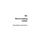
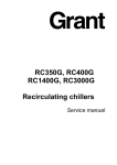
Figure 1.4 illustrates the principle of the RC400G Residual Chlorine Analyzer.
The current flowing between the indicator (ME) and the counter (RE) electrodes is measured
when a specific voltage is applied across the electrodes.
Temperature compensation is implemented through CPU computation based on temperature
signals from the temperature-measuring circuit.
Is
Amplifier
Current/
voltage
conversion
circuit
ME
RE
Voltageapplication
circuit
LED
indicator
CPU
Current/
voltage
output
circuit
4 to 20 mA DC,
or 1 to 5 V DC
Temperaturemeasuring
circuit
Counter electrode
Indicator electrode
Measuring tank
Figure 1.4
F1.4.ai
Schematic Diagram of Measuring Circuit
IM 12F4A1-01E
8th Edition : Aug. 2014
2.
<2. Specifications>
2-1
Specifications
In this chapter, specifications are given for the RC400G Residual Chlorine Analyzer, the RC401G Reagent
Tank and others.
2.1
RC400G Residual Chlorine Analyzer
2.1.1
Standard specifications
n Residual chlorine analyzer
Measurement object: Free chlorine or residual chlorine (total chlorine) in water
Measurement method:Rotating electrode type polarographic system
Measurement range: 0 to 10 mg/l (mg/l used as concentration units per JIS K0101 and municipal water test methods)
Output range:
Can be freely set within ranges with spans of 1 mg/l or greater. (Range
set when shipment. No.1: 0 to 5 mg/l No.2: 0 to 10 mg/l. Allows selection
between 2 ranges (selected with contact input signal).
2-line-segment output available: Any desired point between 0% and
100% of measurement span can be set as the 50% point of the output
range.
Output signal:
4 to 20 mA (load resistance, 550 Ω Max.) or 1 to 5 V DC (output resistance, 300 Ω Max.), isolated
Display range:
-1.00 to 12.00 mg/l
Display method: Digital display (4-digit LED)
Output contacts:
Voltage-free (“dry”) contacts
Contact rating:
Max. 250 V AC, Max. 2 A, Max. 125 VA (resistive load)
Max. 220 V DC, Max. 2 A, Max. 60 W (resistive load)
Input contacts:
Voltage-free (“dry”) contact
ON resistance:
200 Ω Max.
OFF resistance:
100 kΩ Min.
Open circuit voltage: 10 V
Closed circuit current: 100 mA
Automatic zero calibration: Zero calibration using activated charcoal filter (optional)
Contact inputs:
Remote range switching:Switching between 2 preset ranges (range 1 and range 2)
Contact open: Range 1
Contact closed: Range 2
Contact outputs:
FAIL contact:
Activate when concentration over range, measurement temperature error, no liquid in flow cell converter error, temperature compensation over range, setting upper limit exceeded
Range switching contact
MAINT contact:
Activate when analyzer is in maintenance mode
FAIL contact
MAINT contact
Main power OFF
--Open
Closed
Main power ON
Not operating
Operating
Closed
Open
Open
Closed
IM 12F4A1-01E
8th Edition : Aug. 2014
2-2
<2. Specifications>
Sample conditions:
Temperature:
pH:
Flow:
Pressure:
Electrodes:
Indicator electrode:
Counter electrode:
Reagents:
Composition:
0 to 50 °C
pH 3 to 9
1 to 4 l/min, for pure water or municipal water application.
5 to 10 l/min, for raw water or sea water application.
10 to 20 l/min, for secondary sewage treatment application.
20 to 500 kPa
Rotating gold alloy electrode
Platinum electrode (built-in Pt1000 RTD), the combined chlorine
insensitive version uses a silver chlorine electrode.
The following reagents are dissolved in pure water to give 100 l of
solution.
(Note)Pure water should be equal to or exceed level of tap water and should not contain oxidizing and reducing substances
such as chlorine.
For residual chlorine
measurement
Maximum
Up to 6 mg/l Over 6 up to 10 mg/l
concentration
Potassium iodide,
500 g
1000 g
extra pure
Potassium bromide,
----extra pure
Anhydrous sodium
150 g
acetate, extra pure
Glacial acetic acid,
1000 ml
extra pure
For free chlorine
measurement
For combined chlorine
measurement
Up to 10 mg/l
Up to 10 mg/l
---
---
4000 g
4000 g
1000 g
5400 g
1000 ml
200 ml
Consumption: 1.5 ml/min ±10%
Constant flow pump:
Sample flow:
50 ml/min ±10%
Reagent flow:
1.5 ml/min ±10%
Converter functions:
Display functions:
Data:
Concentration, temperature, applied voltage, diffusion current,
output signal %, pump flow, zero point, slope
Status indicators: Measurement, maintenance, hold, calibration in progress, cleaning, fail
Operating status : Rotating gold alloy electrode, mertering pump, air pump, solenoid valve ON/OFF
Diagnostic functions: Concentration over range, measurement temperature error, no liquid in
flow cell, converter error, temperature compensation over range, setting
upper limit exceeded, zero point error, slope error, response error
Maintenance functions (MAINT mode):
One-touch calibration, flow cell and sand filter system cleaning, pump
flow measurement, one-touch plateau characteristic acquisition, failure
error information
Setup functions:
PROGRAM 1 mode
Output Range 1 and Range 2 settings, 2-line-segment output setting,
applied voltage setting, response time and stability parameter settings,
contact output during FAIL condition (ON/OFF), indication hold during
MAINT (ON/OFF), remote range switching ON/OFF
IM 12F4A1-01E
8th Edition : Aug. 2014
2-3
<2. Specifications>
PROGRAM 2 mode
Cleaning sequence setup, auto zero calibration sequence setup
Automatic cleaning functions: Electrode and flow cell cleaning methods
For pure water:
Glass-bead cleaning
For raw/sea water, secondary sewage treatment:
Glass-bead cleaning+water jet cleaning; Water jet cleaning flow: 2 to 3 l/min
Sand filter system:
Filter sand:
Filter sand for municipal water (high-speed filtering sand, approx.
550 ml per tube)
Filtering flow: approx. 500 ml/min (per cylinder)
Backwash water flow: 8 to 9 l/min (per cylinder)
Standard cleaning sequence (factory settings)
1-cylinder system
2-cylinder system
Setting range
Sand filter backwash interval 2 hours
30 min
0.1 to 24 h, 0.1 h steps
Sand filter backwash time
1 min
1 min
0.1 to 25 min, 0.1 min steps
Flow cell jet cleaning interval
2 hours
1 hour
0.1 to 24 h, 0.1 h steps
Flow cell jet cleaning time
1 min
1 min
0.1 to 25 min, 0.1 min steps
Waiting time
5 min
3 min
0.1 to 25 min, 0.1 min steps
Output hold time
6 min
4 min
Jet cleaning time + waiting time
In a 1-cylinder system, sand filter backwash and flow cell jet cleaning are performed at the same time.
Wetted part materials
Measurement tank:
Pump:
Tubing/piping:
Stand materials:
Acrylic resin
Fluorinated rubber (Viton), hardened PVC, SUS316
Polyethylene, hardened PVC
Carbon steel or stainless steel
Paint colors
Mounting stand:
Munsell 0.6GY3.1/2.0
Other parts:
Munsell 0.6GY3.1/2.0 and 2.5Y8.4/1.2
Finish:
Baked polyurethane resin coating
Operating conditions
Ambient temperature: -5 to 55 °C (However, measure to prevent freezing are required if
the water sample or reagent appears to freeze.)
Ambient humidity:
5 to 95% RH (non-condensing)
Storage temperature: -30 to 70 °C
Installation:
Indoors (A separate rainproof cover is required for outdoor installation. Avoid direct sunlight.)
Utilities
Power supply:
100/110/220 V AC ±10%, 50/60 Hz
Power consumption:
RC400G-1: Approx. 65 VA
RC400G-2: Approx. 125 VA
RC400G-3: Approx. 210 VA
Cleaning water (required with sand filter system)
Quality:
clean water
Pressure:
100 to 500 kPa
Flow:
10 to 12 l/min
Consumption: Approx. 130 l/day (1-cylinder sand filter type)
Approx. 470 l/day (2-cylinder sand filter type)
(With standard cleaning sequence [factory settings])
IM 12F4A1-01E
8th Edition : Aug. 2014
2-4
<2. Specifications>
Air purge (using instrument air)
Supply pressure:140 kPa
Air consumption:Approx. 5 l/min
Weight
For pure water: Approx. 65 kg
For raw water (1-cylinder): Approx. 70 kg
For raw water (2-cylinder): Approx. 75 kg
Optional specifications
Pump for air purge (if instrument air cannot be used)
Install to enable intake of clean air.
Intake/discharge:
5 l/min, at 50 Hz (Intake/discharge outlets: Open)
Maximum pressure: 80 kPa
Power consumption: Approx. 23 VA
Weight:
Approx. 2 kg
Regulatory Compliance:
EMC Regulatory Arrangement in Australia and New Zealand (RCM)
EN 55011 Class A, Group 1
한국 전자파적합성 기준
Korea Electromagnetic Conformity Standard Class A
A급 기기 (업무용 방송통신기자재)
이 기기는 업무용(A급) 전자파적합기기로서 판매자 또는
사용자는 이 점을 주의하시기 바라며, 가정외의 지역에서
사용하는 것을 목적으로 합니다.
n Reagent sets (for one year)
l For free chlorine
Potassium bromide extra pure:
Anhydrous sodium acetate extra pure:
Acetic acid extra pure:
64 containers, 500 g each
16 containers, 500 g each
17 containers, 500 ml each
l For residual chlorine (Total chlorine)
Potassium iodide extra pure:
Anhydrous sodium acetate extra pure:
Acetic acid extra pure:
8 containers, 500 g each
3 containers, 500 g each
17 containers, 500 ml each
l For high concentration of residual chlorine (Total chlorine)
Potassium iodide extra pure:
Anhydrous sodium acetate extra pure:
Acetic acid extra pure:
16 containers, 500 g each
3 containers, 500 g each
17 containers, 500 ml each
l For combined chlorine insensitive version (Free chlorine)
Potassium bromide extra pure: 64 containers, 500 g each
Anhydrous sodium acetate extra pure: 87 containers, 500 g each
Acetic acid extra pure: 4 containers, 500 ml each
(Note)These reagents sets are not imported from Japan because of both safety and transportation cost issues. Purchase them directly
in your local reagent supplier.
IM 12F4A1-01E
8th Edition : Aug. 2014
2-5
<2. Specifications>
2.1.2Characteristics
(Percent display is computed with respect to whichever of output range 1 or output range 2 has
the highest upper range value)
Repeatability:
2%
Linearity:
±3%
Drift:
Zero drift:
±1%/month Max.
Span drift:
-5%/month Max.
Response time:
Displayed as 90% response time
For pure water:
Approx. 3 min
For raw water:
Approx. 4 min (Within 3 min from standard liquid inlet)
Temperature compensation error (water temperature):
±1% Max. (Temperature compensation range: 0 to 40 °C)
Effect of ambient temperature: ±0.5%/10 °C
Effect of power variation:
±0.5%/10% of rated voltage
Effect of combined chlorine: 5% or less, of concentration of combined chlorine for combined
chlorine insensitive version
2.1.3Accessories
l Residual chlorine meter
Name
Quantity
Remark
Polishing powder
1 bottle
For polishing electrode
Lubricating oil
1
For metering pump drive
Fuses
4 each
1 A and 3 A (for spare)
Glass beads
1
(including for spare) (2 bags)
Valve sheet
4
For pump (for spare)
1
For sample pump (for spare)
1
For reagent pump (for spare)
Special tool
1
For pump valve replacement
Tool
1
For Bellofram replacement
Allen wrenches
1 set
1.5, 2, 2.5, 4, 5, 6 (mm)
Reagent set
(*)
For startup
Bellofram
(*)
These reagents sets are not imported from Japan because of both safety and transportation cost issues. Purchase them directly in your local reagent supplier.
IM 12F4A1-01E
8th Edition : Aug. 2014
2-6
<2. Specifications>
2.1.4
Product model and suffix codes
l Residual chlorine analyzer
[Style: S3]
Model
Option
code
Suffix code
Description
RC400G
---------------------------------
---------- Residual chlorine analyzer
Application
(cleaning unit)
(*1)
-1
---------- For pure water, for municipal water (with glass-bead
cleaning)
-2
---------- For raw water (1-cylinder) (with glass-beads cleaning, jet
cleaning, and one cylinder sand filter unit) (*6)
-3
---------- For raw water (2-cylinder) (with glass-beads cleaning, jet
cleaning, and two cylinder sand filter unit) (*6)
Output signal
5
---------- 1 to 5 V DC
6
---------- 4 to 20 mA DC
Power supply
Measurement object
(*2)
-
2
---------- 200 V AC, 60 Hz
3
---------- 220 V AC, 50 Hz
4
---------- 220 V AC, 60 Hz
5
---------- 100 V AC, 50 Hz
6
---------- 100 V AC, 60 Hz
7
---------- 110 V AC, 50 Hz
8
---------- 110 V AC, 60 Hz
F
---------- Free chlorine
T
---------- Residual chlorine (total chlorine)
C
---------- Combined chlorine insensitive version (free chlorine) (*3)
---------- Always -N
*A ---------- Always A
Optional specifications
*5:
*6:
*7:
---------- 200 V AC, 50 Hz
-N
-
*1:
*2:
*3:
*4:
1
/AP1
With air purge pump (200 V AC, 50/60 Hz) (*7)
/AP3
With air purge pump (220 V AC, 50/60 Hz) (*7)
/AP5
With air purge pump (100 V AC, 50/60 Hz) (*7)
/AP7
With air purge pump (110 V AC, 50/60 Hz) (*7)
/PPM
Units: ppm
/NR
Without reagent set for start-up (*4)
/SCT
Stainless tag plate
/S
Stainless stand (*5)
/AZC
With automatic zero calibration
/ARS
With arrestor (power and signal lines)
“Application” indicates general guidelines. Select the cleaning equipment appropriate for the contamination in the sample.
Measurement object selection is indicated in the following.
Less affected by combined chlorine in free chlorine measurement.
When ordering the RC400G, select /NR and get reagent sets for start-up from local reagent supplier.
These reagent sets can not be exported from Japan due to both safety and transportation issues.
Stanchion, base and bracket are stainless steel.
Please contact Yokogawa regarding the adequate number of the cylinder.
Installation of air purge is always required for all application. If instrument air cannot be used, select the air purge pump.
IM 12F4A1-01E
8th Edition : Aug. 2014
<2. Specifications>
2-7
Measurement object
Application
Free chlorine
Total chlorine
Water purification: raw water
(*1)
Water purification: mixed water, sedimentation water
(*1)
Water purification: mains water
Sea water
x
x (*3)
Factory wastewater, treated effluent
x
x
Factory cooling water (industrial water)
x
(*2)
Factory drinking water
Sewage secondary treatment
x
x (*3)
: Can be measured
x: Cannot be measured
*1:
If ammoniacal contaminants are present in large quantity, high concentrations of combined chlorine may remain if sampling is
performed soon after chlorine injection in prechlorination treatment, or in intermediate treatment without prechlorination treatment. In this case, combined chlorine type is recommended
*2:
Oxidizing or reducing agents other than chlorine may be present. If so, chlorine concentration measurement may not be possible.
*3:
There are Residual chlorine analyzer for sewage secondary treatment or sea water. Please ask.
l Spare parts
Name
Indicator electrode
(Rotating electrode)
Part No.
K9334JP
Description
Q'ty
Recommended
replacement interval (*1)
Gold alloy electrode (*4)
1
Yearly
(*2)
Counter electrode
K9332MJ
Reference electrode
1
Counter electrode
K9332MK
For combined chlorine insensitive type
1
(*2)
Glass beads
K9332ZJ
For cleaning indicator electrode. (2 bags/Q’ty)
1
Yearly
Polishing powder (Alumina)
K9088PE
For polishing indicator electrode
1
-
Brush
K9332JX
Part for electrode mechanism
1
2 years
Slip ring
K9332JZ
Part for electrode mechanism
1
2 years
Drive belt
L9804UK
Part for electrode mechanism
1
3 years
Driven shaft assembly
K9334JV
Part for electrode mechanism (*4)
1
3 years
O-ring
Y9115XB
Part for electrode mechanism
1
3 years
Motor assembly (100 V)
K9334JY
Part for electrode mechanism
1
3 years
Motor assembly (110 V)
K9334VQ
Part for electrode mechanism
1
3 years
Motor assembly (200 V)
K9334VR
Part for electrode mechanism
1
3 years
Motor assembly (220 V)
K9334VS
Part for electrode mechanism
1
3 years
Gear head (100 V / 110 V)
K9332JP
Part for electrode mechanism
1
3 years
Gear head (200 V/220 V)
K9334VA
Part for electrode mechanism
1
3 years
Fuse (1 A)
A1109EF
For electric circuit
1
Yearly (*5)
Fuse (3A)
A1113EF
For power supply
1
Yearly (*5)
Sand
K9720FZ
For sand filter unit (1liter)
1
yearly
Air pump (100 V)
K9087XA
For air purgepump
1
3 years
Air pump (110 V)
K9087XF
For air purgepump
1
3 years
Air pump (200 V)
K9087XG
For air purgepump
1
3 years
Air pump (220 V)
K9087XH
For air purgepump
1
3 years
Lubricating oil (engine oil)
K9041RA
For metering pump drive
1
1 month (*3)
Bellofram
L9819AA
For reagent pump
1
6 months
Bellopfram
L9819AB
For sample water pump
1
6 months
Valve sheet
K9041HC
For metering pump
1
6 months
Activated charcoal filter
L9862AY
For automatic zero calibration
1
Yearly
Filter
K9332NN
For head tank or sand filter
1
Yearly
(*1)
(*3)
(*5)
Replacement intervals vary depending on the application.
(*2) At the time of damage
30 ml, for lubricating the metering pump drive assembly
(*4) P/N changed by style S3.
Fuse may be used more than one year, we recommend periodical replace for planning maintenance.
IM 12F4A1-01E
8th Edition : Aug. 2014
2-8
<2. Specifications>
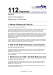
2.1.5
Flow diagrams and outline drawings
n RC400G-1 Residual chlorine analyzer for tap water
unit : mm
Air purge inlet
Rc1/4(female)
Standard solution inlet
Rc1/4(female)
Reagent inlet
Rc1/4 (female)
Maintenance
space
Approx. 200
530
Stand
600
Front
350
Ball valve (V3)
Approx. 500
100
4-ø15 holes
for anchor bolt
Maintenance
space
Approx. 200
100
Strainer (S1)
20
490
Maintenance
space
20
Cross section A-A
Air pump (*3)
Converter
(CON)
(AP)
Detector
(CELL)
Power terminal
box (*1)
Head tank
(HD)
Ball valve
(V11,12)
(*2)
(F11) (*2)
A
3-way solenoid
valve (SV6)
(*2)
530
Ball valve (*2)
(V4)
Measuring
sample inlet
VP16 pipe
93
A
Pressure reducing
valve (*2) (PR)
Ball valve
(V1)
550
50
Tap water inlet
VP16 pipe
(*2)
120
Activated
charcoal filter
80
(V2)
Drain
VP40 pipe
1450
Metering
pump
(PU)
Meas. / Std. solution
switching valve
85 60
150
40
150
(*1) Option / ARS applies to model with arrestors
(*2) Option / AZC applies to model with auto zero calibration
(*3) Option / AP applies to model with air purge pump
F2_1E.ai
IM 12F4A1-01E
8th Edition : Aug. 2014
2-9
<2. Specifications>
n RC400G-2 Residual chlorine analyzer for raw water with one cylinder
sand filter unit
unit : mm
Air purge inlet
Rc1/4 (female)
Standard solution inlet
Rc1/4 (female)
Reagent inlet
Rc1/4 (female)
Maintenance
4-ø15 holes
for anchor bolt
Maintenance
space
Approx. 200
space
Approx. 200
Stand
600
350
Ball valve (V6)
Front
Approx. 500
100
530
100
Strainer (S1)
20
490
20
Maintenance
space
Cross section A-A
Air pump (*3)
(AP)
Detector
(CELL)
Sand filter
(F1)
Solenoid
valve
(SV1,2)
Ball valve
(V1)
Drain VP40 pipe
Ball valve
(V11,12)
Activated
charcoal filter
(F11) (*2)
Ball valve
(V3)
(*2)
3-way solenoid
A
valve (SV6)
A
Ball valve
(V4)
Measuring
sample inlet
VP16 pipe
93
(*2)
530
Pressure reducing
valve (PR)
550
Tap water inlet
VP16 pipe
120
Metering
pump
(PU)
Meas. / Std. solution
switching valve
(V5)
1450
Ball valve
(V2)
Power terminal
box (*1)
80
Converter
(CON)
50
(*1) Option / ARS applies to model with arrestors
(*2) Option /AZC applies to model with auto zero calibration
(*3) Option / AP applies to model with air purge pump
F2_2E.ai
IM 12F4A1-01E
8th Edition : Aug. 2014
2-10
<2. Specifications>
n RC400G-3 Residual chlorine analyzer for treated water with two cylinder sand filter unit
unit : mm
Air purge inlet
Rc1/4 (female)
Standard solution inlet
Rc1/4 (female)
Reagent inlet
Rc1/4 (female)
Maintenance
530
Maintenance
space
Approx. 200
Stand
600
350
Ball valve (V8)
Front
Approx. 500
100
4-ø15 holes
for anchor bolt
space
Approx. 200
100
Strainer (S1)
20
490
20
Maintenance
space
Cross section A-A
Air pump (*3)
(AP)
Converter
(CON)
Detector
(CELL)
Sand filter
(F2)
Sand filter
(F1)
Solenoid
valve (SV1)
Solenoid
valve (SV3, 4)
Ball valve
(V1, 5)
Ball valve
(V2)
Solenoid
valve (SV1, 2, 5)
Power terminal
box (*1)
(PU)
Drain
VP40 pipe
1450
Metering
pump
Meas. / Std. solution
switching valve (V7)
Pressure reducing
valve (PR)
Ball valve
(V11,12)
(*2)
93
530
550
50
Tap water inlet
VP16 pipe
120
A
A
Ball valve
(V4)
Measuring
sample inlet
VP16 pipe
3-way solenoid
valve (SV6)
(*2)
80
Activated
charcoal filter
(F11) (*2)
85 60
150
40
150
(*1) Option /ARS applies to model with arrestors
(*2) Option /AZC applies to model with auto zero calibration
(*3) Option / AP applies to model with air purge pump
F2_3E.ai
IM 12F4A1-01E
8th Edition : Aug. 2014
2.2
2-11
<2. Specifications>
RC401G Reagent Tank
It is a tank to hold reagent to be supplied to the residual chlorine analyzer. It is equipped with a
stirrer (manual) and a level gauge.
Either a tank only or a tank installed on a stand are available.
NOTE
When the tank with a stand (RC401G-B) is used, open a needle valve gradually and stop it at the
position when reagent starts to flow. Don’t open more, otherwise leakage may happen.
2.2.1
(1)
Standard specifications
Reagent tank (RC401G-A)
Capacity:
100 l
Materials:
Rigid PVC
Weight:
Approx. 15 kg
Other:
With manual mixer, and level gauge
(2)
Reagent tank with stand (RC401G-B)
Incorporates the reagent tank in item (1) with a stand and a needle valve.
Materials:
Carbon steel
Stand color:
Munsell 2.5Y8.4/1.2
Stand finish:
Baked polyurethane resin coating
Weight:
Approx. 25 kg
(3)
Reagent mixing tank with cart (RC401G-C)
This is a tank to prepare reagent. It is mounted on a cart and provided with a manual stirrer and a
pump to transfer the prepared reagent to the reagent tank (RC401G). The pump is driven by 100
V AC.
A reagent mixing tank mounted on a cart. With manual mixer, and pump for transferring reagents.
Note: This tank is for reagent mixing, and is not a substitute for the reagent tank.
Tank capacity: 100 L
Tank materials:Rigid PVC
Cart materials:
Frame: Steel pipe (SPG30A)
Bracket: Steel plate (SPCC)
Pump (Seal-less Pump)
Discharge flow rate: 14 to 35 L/min
Wetted part material: Polypropylene resin, Hastelloy, ceramics, fluorinated rubber
Power supply: 100 V AC, 50/60 Hz
Power consumption: Approx. 100 VA
Power cord: PVC sheathed cable, 5 m
Weight:
Approx. 40 kg
IM 12F4A1-01E
8th Edition : Aug. 2014
<2. Specifications>
2.2.2
2-12
Product model and suffix codes
Model
Suffix code
Option code
Description
RC401G
-----------------------
--------------------
Reagent tank
Type
-A
--------------------
Reagent tank only
-B
--------------------
Reagent tank with stand
--------------------
Reagent mixing tank with mobile stand
--------------------
With manual mixer
--------------------
Style A
-C
-
-HM
-
*A
2.2.3Accessories
l Reagent tank (RC401G-A, RC401G-B)
Name
Quantity
Couplings
2 sets
Polyethylene tubing
5m
Remark
Outside diameter 6 mm, Inside
diameter 4 mm.
Note: These are not included in reagent mising tank (RC401G-C).
2.2.4
Outline drawings
Unit: mm
● RC401G-B
● RC401G-A
Reagent tank
415 450
Reagent output
(Rc1/4)
415
Reagent input
Needle
valve
Manual mixer
Approx.1600
Level gauge
Reagent
output
(Rc1/4)
Approx.
Approx.
955
805
Approx.
700
20
225
410
450
(20)
100
250
450
4-ø13 holes
(100)
● RC401G-C
Approx.1280
770
460
F0204.ai
IM 12F4A1-01E
8th Edition : Aug. 2014
3.
3-1
<3. Installation, Tubing and Wiring>
Installation, Tubing and Wiring
Instructions for installation, tubing and wiring of the RC400G Residual Chlorine Analyzer
are given in this chapter.
When transferring the RC400G from storage or in unpacking it, observe the caution in the
foreword in the early part of this user’s manual.
3.1Installation
3.1.1
Location
Install the RC400G analyzer in a location to satisfying the following conditions.
• A building or a cabinet free rain water.
• Slight vibration
• Substantially free from corrosive gases.
• Low humidity.
• Slight temperature variation. Ambient temperature should be approximately maintainable
near ordinary temperatures.
• Sufficient and accessible space for maintenance.
• Provision for drainage.
3.1.2Installation
Securely fix the analyzer to a well-drained concrete foundation or the equivalent.
NOTE
Refer to the external dimension figures in Chapter 2 for the position of anchor bolting, etc..
When using “RC401G-A Reagent Tank” for supplying reagent to the analyzer, install the tank in
such a manner that its bottom is positioned about 70 cm above the floor surface where the analyzer is installed.
3.2
Tubing
Tubing for the analyzer include the following:
(1) Sample water tubing [see subsection 3.2.1]
(2) Reagent tubing [see subsection 3.2.2]
(3) Washing water tubing (for raw or treated water type analyzers) [see subsection 3.2.3]
(4) Drain tubing [see subsection 3.2.4]
(5) Purge air tubing (when the analyzer is not provided with air pump) [see subsection 3.2.5]
(6) Standard solution tubing (for calibration) [see subsection 3.2.6]
(7) Automatic zero calibration tubing [see subsection 3.2.7]
IM 12F4A1-01E
8th Edition : Aug. 2014
<3. Installation, Tubing and Wiring>
3-2
Tubing connections and flow charts for the RC400G-1, RC400G-2 and RC400G-3 are illustrated in Figure 3.1.1 to 3.1.3, Figure 3.2.1 to 3.2.3 and Figure 3.3.1 to 3.3.3, respectively.
(1) RC400G-1 Residual Chlorine Analyzer for Tap Water
Drain
VP40 pipe
Standard solution inlet
For air purge inlet
Reagent inlet
Measuring sample inlet
VP16 pipe
Tap water inlet (*1)
VP16 pipe
(*1) Option /AZC applies to model with auto zero calibration
F3_1_1E.ai
Figure 3.1.1
Piping of RC400G-1 Residual Chlorine Analyzer for Tap Water
Tubing materials
ø6 x ø4
polyethylene tube
Converter
ø22 x ø15
braided wire reinforced
soft PVC tube
ø33 x ø25
braided wire reinforced
soft PVC tube
HD
Head tank
CON
VP16 pipe
CELL Measuring
tank
VP40 pipe
* option
PU
Metering
pump
Ball valve
V2
COM
Measuring sample (VP16)
Standard solution (Rc1/4)
Reagent (Rc1/4)
Air (Rc1/4)
V1
V3
Strainer
S1
AP
*Air pump
Vat
Drain (VP40)
F1_4_1E.ai
Figure 3.1.2
Tubing Diagram of RC400G-1
IM 12F4A1-01E
8th Edition : Aug. 2014
3-3
<3. Installation, Tubing and Wiring>
Tubing materials
ø6 x ø4
polyethylene tube
Converter
ø22 x ø15
braided wire reinforced
soft PVC tube
ø33 x ø25
braided wire reinforced
soft PVC tube
HD
Head tank
VP16 pipe
CON
V12
VP40 pipe
SV6 NO
3-way solenoid
valve
* option
NC
Measuring sample (VP16)
Calibration solution (VP16)
Standard solution (Rc1/4)
Reagent (Rc1/4)
Air (Rc1/4)
Ball valve
V1
CELL Measuring
tank
COM
Activated
charcoal
filter
F11
Ball
valve
V11
V2
PU
Metering
pump
COM
Pressure reducing valve
V13
PR
V3
Strainer
S1
AP
Vat
*Air pump
Drain (VP40)
F1_4_4E.ai
Figure 3.1.3
Tubing Diagram RC400G-1/AZC
(2) RC400G-2 Residual Chlorine Analyzer for Raw Water
Drain
VP40 pipe
Standard solution inlet
For air purge inlet
Measuring sample inlet
VR16 pipe
Reagent inlet
Tap water inlet
VR16 pipe
F3_2_1E.ai
Figure 3.2.1
Piping of RC400G-2 Residual Chlorine Analyzer for Raw Water
IM 12F4A1-01E
8th Edition : Aug. 2014
3-4
<3. Installation, Tubing and Wiring>
Tubing materials
ø6 x ø4
polyethylene tube
ø8 x ø6
polyethylene tube
Converter
Sand filter
F1
CON
ø22 x ø15
braided wire reinforced
soft PVC tube
ø33 x ø25
braided wire reinforced
soft PVC tube
CELL Measuring
tank
V1
VP16 pipe
VP40 pipe
V2
* option
PU
Metering
pump
Ball valve
V5
V3
SV1
Measuring sample (VP16)
Pressure reducing valve
V4
Tap water (VP16)
Ball valve PR
Standard solution (Rc1/4)
V6
Strainer
Reagent (Rc1/4)
S1
COM
Solenoid
valve
SV2
AP
Air (Rc1/4)
*Air pump
Vat
Drain (VP40)
F1_4_2E.ai
Figure 3.2.2
Tubing Diagram of RC400G-2
Tubing materials
ø6 x ø4
polyethylene tube
ø8 x ø6
polyethylene tube
F1
Converter
CON
Sand filter
ø22 x ø15
braided wire reinforced soft PVC tube
ø33 x ø25
braided wire reinforced soft PVC tube
VP16 pipe
V1
V12
VP40 pipe
SV6
* option
NC
V3
Measuring sample (VP16)
SV1
Pressure reducing valve
V4
Tap water (VP16)
PR
Ball valve
Standard solution (Rc1/4)
Strainer
V6
S1
Reagent (Rc1/4)
Air (Rc1/4)
CELL Measuring
tank
Solenoid
valve
NO
3-way solenoid
valve
V2
COM
Activated
charcoal
filter
Ball
valve
F11
V5
V11
PU
Metering
pump
COM
SV2
AP
*Air pump
Vat
Drain (VP40)
F1_4_5E.ai
Figure 3.2.3
Tubing Diagram of RC400G-2/AZC
IM 12F4A1-01E
8th Edition : Aug. 2014
3-5
<3. Installation, Tubing and Wiring>
(3) RC400G-3 Residual Chlorine Analyzer for Treated Water
Drain
VP40 pipe
Standard solution inlet
For air purge inlet
Reagent inlet
Measuring sample inlet
Tap water inlet
VP16 pipe
VP16 pipe
F3_3_1E.ai
Figure 3.3.1
Piping of RC400G-3 Residual Chlorine Analyzer for Treated Water
Tubing materials
Converter
ø6 x ø4
polyethylene tube
F1
ø8 x ø6
polyethylene tube
ø22 x ø15
braided wire reinforced
soft PVC tube
ø33 x ø25
braided wire reinforced
soft PVC tube
Sand filter
Sand filter
F2
CON
Solenoid valve
SV4
SV3
V1
CELL Measuring
tank
V5
VP16 pipe
V2
VP40 pipe
* option
PU
V4
Ball valve
V3
V7
Measuring sample (VP16)
Pressure reducing valve
V6
Tap water (VP16)
PR
Standard solution (Rc1/4)
Reagent (Rc1/4)
Air (Rc1/4)
Metering
pump
V8
SV1
SV5
COM
SV2
Strainer
S1
AP
*Air pump
Vat
Drain (VP40)
F1_4_3E.ai
Figure 3.3.2
Tubing Diagram of RC400G-3
IM 12F4A1-01E
8th Edition : Aug. 2014
3-6
<3. Installation, Tubing and Wiring>
Tubing materials
ø6 x ø4
polyethylene tube
Converter
F1 Sand filter
F2
Sand filter
ø8 x ø6
polyethylene tube
ø22 x ø15
braided wire reinforced
soft PVC tube
CON
Solenoid valve
SV4
SV3
ø33 x ø25
braided wire reinforced
soft PVC tube
V1
VP16 pipe
VP40 pipe
V12
CELL Measuring
tank
Metering
pump
V2
V5
3-way solenoid
valve SV6 COM
* option
NC
V4
V3
Ball valve
Measuring sample (VP16)
SV1
Pressure reducing valve
V6
Tap water (VP16)
PR
Standard solution (Rc1/4)
Reagent (Rc1/4)
Air (Rc1/4)
V8
NO
F11
Activated
charcoal
V11 filter
Ball
SV5
valve
PU
V7
COM
SV2
Strainer
S1
AP
*Air pump
Vat
Drain (VP40)
F1_4_6E.ai
Figure 3.3.3
3.2.1
Tubing Diagram of RC400G-3/AZC
Sample Water Tubing
This is the tubing for taking sample water and feeding it to the analyzer.
The connection is a rigid PVC tube of nominal dia. 16 (O.D. 22 mm). Implement tubing using
proper joints, i.e. unions and flanges etc., which fit the connection. Note: Perform tubing so that
sample water pressure at the connection falls within the range of 20 to 500 kPa.
Sample water flow rates to the analyzer in operation are as follows:
3.2.2
In RC400G-1:
In RC400G-2:
In RC400G-3:
1 to 4 l/min
5 to 10 l/min
10 to 20 l/min
Reagent Tubing
Residual chlorine content is determined by sample water mixed with reagent. The reagent tubing
supplies reagent to the measuring cell of the analyzer.
Connect the outlet of the reagent tank to the reagent inlet of the analyzer using Rc1/4 joint and
O.D. 6 mm x I.D. 4 mm polyethylene tube.
There is a reagent level limit in the tank.
Check that the position of the reagent tank is in accordance with Figure 2.4 RC401G Reagent
Tank.
3.2.3
Cleaning Water Tubing
This tubing is required for the raw water type and treated water type analyzers.
In these types of analyzers, intake sample water is filtered by the sand filter. For maintaining
filtering capacity, the sand filter is flushed with water at regular intervals to remove floccules, etc.
deposited in the filter.
IM 12F4A1-01E
8th Edition : Aug. 2014
3-7
<3. Installation, Tubing and Wiring>
The cleaning water tubing leads tap water for washing to the analyzer.
The connection is a rigid PVC tube of nominal dia. 16 (O.D. 22 mm).
Perform tubing in the same manner as the sample water tubing, using proper joints, so as to allow cleaning water pressure to fall within the range of 100 to 500 kPa.
3.2.4
Drain Tubing
This is the tubing to discharge sample water and cleaning water from the analyzer to a drainage
ditch, etc..
The specifications of the tubing connections are given below.
In RC400G-1:
In RC400G-2:
In RC400G-3:
Rigid PVC tube, nominal dia. 40 (O.D. 48 mm)
Rigid PVC tube, nominal dia. 40 (O.D. 48 mm)
Rigid PVC tube, nominal dia. 40 (O.D. 48 mm)
Perform tubing so as to prevent sedimentation and formation of any dead spot in the tubing.
3.2.5
Purge Air Tubing
This is the tubing to supply clean dry air to the cases which house the converter, electrode
mechanism block and pump drive assembly for air purging.
When the RC400G is provided with an air pump, extend the tubing to an area free from corrosive gases for intake of clean air. If an air pump is not available, employ instrument air, etc. and
perform tubing so that air is supplied at a pressure of approx. 140 kPa.
The connection is Rc1/4.
3.2.6
Standard Solution Tubing
This supplies standard solution to the analyzer for calibrating zero point or span.
Usually, this tubing is set up every time when calibration (refer to Chapter 7) is conducted.
The tubing connection is Rc1/4.
NOTE
Standard solution supplied from the tubing connection is directly fed to the metering pump. If the
pressure of the supplied standard solution largely exceeds 10 kPa, standard solution may enter
the reagent line or some quantity of solution more than specified may be sent to the detector
causing the measuring cell to overflow. As a rule, standard solution should be supplied only in the
manner described in Chapter 7.
3.2.7
Automatic Zero Calibration Tubing
This is the tubing that is used when zero calibration using an activated charcoal filter is performed. If the option has been specified, this tubing is installed at the factory before shipment.
IM 12F4A1-01E
8th Edition : Aug. 2014
3.3
<3. Installation, Tubing and Wiring>
3-8
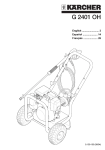
Wiring
The type of wiring required by the residual chlorine analyzer are as shown below. All are connected to wiring terminals (M4 screw) in the converter. When the analyzer with arrestors, connect
terminals of power and analog output to the terminal box.
(1) Wiring for power supply and grounding.
(2) Wiring for analog output signals.
(3) Wiring for contact input (<remote> range switching).
(4) Wiring for contact output (<maintenance>, <failure>). (when required)
Analyzer converter
Range
1
2
output
POWER
L1 L2
Grounding
Receiver
G
+
OUTPUT –
R1
RANGE R2
FAIL
M1
M2
F1
F2
Analog output signal wiring
+
–
Contact input wiring for range selection
G
<maintenance> contact
<failure> contact output
Power supply
Power supply
F030401.ai
Figure 3.4
External Wiring Diagram
IM 12F4A1-01E
8th Edition : Aug. 2014
3-9
<3. Installation, Tubing and Wiring>
RC400G-1 Residual Chlorine Analyzer for Tap Water
Converter
(CON)
Fail contact output
Maintenance contact output
(Wired by customer)
Range switching output
Remote range switching input
Power terminal box
ME
F2
RE
M1
T1
M2
T2
O1
G
O2
C1
R1
C2
(*2)
Analog output
+
S
AR2x2
F1
Dedicated cable
K9332WA
Bk
Detector
(CELL)
ME
W
RE
Bw
T1
Gn
T2
Terminal
mounting
C1 screw
Rd
Bl
C2
R2
-
+
P1
G
G
P2
Dedicated cable
K9332WB
Bk
Pump
(PU)
P1
P2
W
G
+
G
G
L2
L2
L1
L1
G
V1
L2
V2
L1
G
CB1
2
G
L1
1 AR1
A1
* Case ground terminal must be
grounded.
If this is not possible connect
to power source ground wire.
AR1,2 : Arrestors
CB1 : Circuit breaker
A2
Power
Figure 3.5
Dedicated cable
K9460CN
Bk
Analog output
Solenoid valve
(option)
(SV6) (*1)
1
2
W
L2
* Ground
Dedicated cable
K9332WJ
Bk
W
Air pump
(option)
(AP) (*3)
A1
A2
(Note)
F16.EPS
Dotted lines : external wiring
Use cable of 6 to 12 mm OD, however when connecting via power
terminal box option use cable of 9 to 11 mm OD for both power and
analog output cables.
(*1) Option /AZC applies to auto zero calibration
(*2) Option /ARS applies to version with arrestor
(*3) Option /AP applies to version with air purge pump
RC400G-1/ARC/AZC
IM 12F4A1-01E
8th Edition : Aug. 2014
3-10
<3. Installation, Tubing and Wiring>
RC400G-2 Residual Chlorine Analyzer for Raw Water
Converter
(CON)
Fail contact output
Maintenance contact output
(Wired by customer)
Range switching output
Remote range switching input
F1
ME
F2
RE
M1
T1
M2
T2
O1
G
O2
C1
R1
C2
Power terminal box (*2)
Analog output
+
S
AR2x2
Dedicated cable
K9332WA
Bk
W
T1
Gn
T2
Terminal
mounting
C1 screw
Rd
Bl
C2
Dedicated cable
-
P1
+
G
P2
G
G
K9332WB
Bk
L1
G
L2
L2
B1
L1
B2
L1
2
1
G
J1
J2
L1
K9332WC
Bk
Power
V1
V2
Analog output
A1
A2
Solenoid valve
(SV1)
1
2
W
K9332WD
Bk
Solenoid valve
(SV2)
1
2
W
AR1
* Case ground terminal must be
grounded.
If this is not possible connect to
power source ground wire.
AR1,2 : Arrestors
CB1 : Circuit breaker
P1
G
Dedicated cable
L2
Pump
(PU)
P2
W
Dedicated cable
G
L2
CB1
ME
RE
Bw
+
G
Detector
(CELL)
R2
* Ground
Dedicated cable
K9460CN
Bk
W
Dedicated cable
K9332WJ
Bk
Solenoid valve
(SV6) (*1)
1
2
Air pump (option)
(AP) (*3)
A1
A2
W
(Note)
Dotted lines : external wiring
Use cable of 6 to 12 mm OD, however when connecting via power
terminal box option use cable of 9 to 11 mm OD for both power and
analog output cables.
(*1) Option /AZC applies to auto zero calibration
(*2) Option /ARS applies to version with arrestor
(*3) Option /AP applies to version with air purge pump
F17.EPS
Figure 3.6
RC400G-2/ARS/AZC
IM 12F4A1-01E
8th Edition : Aug. 2014
3-11
<3. Installation, Tubing and Wiring>
RC400G-3 Residual Chlorine Analyzer for Raw Water
Converter
(CON)
(Wired by customer)
Fail contact output
Maintenance contact output
F1
ME
F2
RE
M1
T1
M2
T2
Range switching output
O1
G
O2
C1
Remote range switching input
R1
C2
Power terminal box (*2)
-
AR2x2
Dedicated cable
K9332WA
Bk
W
Bw
Gn
Rd
Bl
Detector
(CELL)
ME
RE
T1
T2
Terminal
mounting
C1 screw
C2
R2
Analog
output
-
+
+
S
G
+
P1
P2
G
Dedicated cable
K9332WB
Bk
W
Pump
(PU)
P1
P2
G
Dedicated cable
K9332WL
J1
G
G
L2
Bk
J2
W
L2
L1
L1
G
L2
Dedicated cable
K9460CN
L1
G
CB1
2
1
G
V1
L2
Bk
V2
L1
AR1
* Ground
G
W
Dedicated cable
K9332WK
Terminal box
B1
B2
Power Analog
output
* Case ground terminal must be
grounded.
If this is not possible connect to
power source ground wire.
AR1,2 : Arrestors
CB1 : Circuit breaker
1
Dedicated cable
K9332WH
2
Bk
W
3
B3
4
B4
Dedicated cable
K9332WG
Bk
5
S1
6
S2
7
S3
8
S4
A1
A2
W
Dedicated cable
K9332WJ
Bk
W
Air pump (option)
(AP) (*3)
Dedicated cable
K9332WE
Bk
W
Dedicated cable
K9332WF
Bk
W
Solenoid valve
(SV2)
1
2
Solenoid valve
(SV6) (*)
(option)
1
2
Solenoid valve
(SV1)
1
2
Solenoid valve
(SV5)
1
2
Solenoid valve
(SV3)
1
2
Solenoid valve
(SV4)
1
2
A1
A2
(Note)
Dotted lines : external wiring
Use cable of 6 to 12 mm OD, however when connecting via
power terminal box option use cable of 9 to 11 mm OD for both
power and analog output cables.
(*1) Option /AZC applies to auto zero calibration
(*2) Option /ARS applies to version with arrestor
(*3) Option /AP applies to version with air purge pump
F18.EPS
Figure 3.7
RC400G-3/ARS/AZC
IM 12F4A1-01E
8th Edition : Aug. 2014
3-12
<3. Installation, Tubing and Wiring>
SV1 SV2 SV3 SV4 SV5 SV6
5
MEAS
MABT
ppm
PROGRAM 1
PROGRAM 2
DATASET
,
.
MODE
,
MANUAL OPERATION
SY1
SY2
SY3
SY4
SY5
SY6
Wiring terminal board
+
-
R1
R2
T1
T2
O
O1
11
U1
O2
12
U2
O1
U3
V1
V2
O2
P1
P2
M1
V4
J1
J2
M2
L2
L1
A1
A2
U4
V3
Wiring cable inlet port
(3 or 4 ports for external wiring)
Figure 3.8
F3.5.ai
External Wiring Terminal Board and Cable Inlet Port in Converter
Whereas the converter has 8 cable inlet ports, 5 out of the 8 ports have been assigned to internal
wiring and only 3 ports are available for external wiring.
NOTE
In the RC400G-1 analyzer which has no air pump, 4 ports are available for external wiring.
Use one cable for each wiring. The analog output wiring and contact input wiring are collected
together in one cable as a rule, but they can be assigned separate cables if cable ports are available.
NOTE
Stop cable ports not in use with plugged cable glands.
IM 12F4A1-01E
8th Edition : Aug. 2014
3-13
<3. Installation, Tubing and Wiring>
3.3.1
Wiring for Power Supply and Grounding
This is for supplying power of voltage and frequency meeting the specification of the analyzer
and for grounding the converter case.
Connect the terminals L1 and L2 of the converter to power supply with a two-conductor cable of 6
to 12 mm finished O.D..
When the analyzer is equipped with arrestors (when option code “/ARS” is specified), connect
terminals L1 and L2 to the power terminal box (a circuit breaker is incorporated).
Refer to Figures 3.5 to 3.7.
NOTE
The converter does not have a power switch. A double-pole switch should be installed in the
power line. A power switch for the converter is necessary to prevent electric shock or damage to
the instrument when inspection or maintenance of electric system is performed with power supplied.
Treat the end of cable to be connected to the converter terminal in the following manner:
(1) Strip of the insulation covering from the cable at its end approx. 80 mm.
(2) Attach to the tip of the conductor a crimping type terminal lug which fits an M4 screw.
For grounding, use the grounding terminal marked “
” at the bottom of the converter case.
Provide grounding by connecting the end-treated (for sufficient conduction) grounding lead to the
M5 screw of the grounding terminal (grounding resistance must be 100 Ω or less).
NOTE
When the grounding terminal of the converter case cannot be used, connect the grounding lead
to terminal G (M4 screw) inside the converter and ground the lead at the power supply. For this,
use a two- or three-conductor shielded cable for power supply and grounding wiring.
+
-
R1
R2
11
U1
T1
T2
O
O1
O2
12
U2
O1
U3
V1
V2
O2
P1
P2
M1
V4
J1
J2
M2
G
L2
L1
A1
A2
U4
V3
Power fuse
F3.6.ai
Figure 3.9
Wiring Terminals of Converter
IM 12F4A1-01E
8th Edition : Aug. 2014
3.3.2
3-14
<3. Installation, Tubing and Wiring>
Wiring for Analog Output Signals
This is for transmitting output signals of 1 to 5 V DC or 4 to 20 mA DC by the respective range to
receives such as a recorder. Use a two-conductor shielded cable of 6 to 12 mm finished O.D..
When the analyzer is equipped with arrestors (when option code “/ARS” is specified), connect
terminals L1 and L2 to the power terminal box (a circuit breaker is incorporated).
Refer to Figures 3.5 to 3.7.
NOTE
For <remote> range switching, use a four-conductor (including this wiring) shielded cable.
Treat the cable at its end to be connected to the converter terminal in the following manner.
(1) Strip of the insulation covering of the cable at its end, approx. 60 mm, and solder a lead wire
to the base of the exposed shield.
Protect the soldered part by wrapping with insulation tape or other means.
(2) Cut the lead wire and each conductor to equal length and attach to the lead wire and conductors tips crimping type terminal lugs which fit M4 screws.
(3) Connect the cable to + and - terminals of the converter. Connect the positive pole conductor
to the terminal OUTPUT at “+”, and the negative pole conductor to “-”, respectively.
3.3.3
Connect the lead wire of the shield to terminal G. (Do not double ground the shield connected to terminal G at the receiver end.)
Wiring for Contact Input (<remote> Range Switching)
The two output ranges are switchable to each other arbitrarily. Range switching can be performed either <remote> or <local>.
The wiring herewith described is provided for switching the range with <remote> (see subsection
5.3.4 (10)).
Use the remainder of the cable used for the analog output signal wiring described in subsection
3.3.2.
Connect the two conductors of the cable to terminals R1 and R2.
NOTE
When cable inlet ports are available, the wiring described above can be made with two separate
cables. For that, employ a two-conductor cable of 6 to 12 mm finished O.D.. Treat the cable end
in the same manner as the analog output signal cable.
Contact inputs ON (“Output range-2” is selected) and OFF (“Output range-1” is selected) are
identified by the resistance condition shown in Table 3.1. On wiring, ensure that a contact meeting this condition is used.
Table 3.1
Identification of ON and OFF of Contact Input for <remote> Range Selection
Identification ON (Output range-2)
Resistance (contact)
200 W or less
Identification OFF (Output range-1)
100 kW or more
IM 12F4A1-01E
8th Edition : Aug. 2014
3.3.4
<3. Installation, Tubing and Wiring>
3-15
Wiring for Contact Output
The converter supplies contact signals of either <failure>, <maintenance> or <range>, for which
contact output wiring is provided.
For the wiring, use a cable or 6 to 12 mm finished O.D. (select a two-, three- or four-conductor
cable depending on the number of contract outputs used.)
Treat the cable end to be connected to the converter terminals in the same manner as the analog
output signal cable (see subsection 3.3.2.)
Connect each conductor of the cable to terminals F1, F2 (contact output <failure>), M1, M2 (contact output <maintenance>) and O1, O2 (<range> switching contact), respectively.
Contact capacity of the contact output relay is given in Table 3.2. Equipment to be connected
must meet the condition shown by the table.
Table 3.2
Contact Capacity of Contact Output Relay
Contact maximum allowable voltage
Contact maximum allowable current
Contact maximum allowable power
with DC
with AC
220 V
2A
60 W
250 V
2A
125 VA
IM 12F4A1-01E
8th Edition : Aug. 2014
Blank Page
8th Edition : Aug. 2014
4-1
<4. Operation>
4.
Operation
This chapter chiefly describes preparation procedures for stable analyzer operation.
4.1
Component Identification and Function
<RC400G-1>
Air pump (*3)
Converter
(CON)
(AP)
Detector
(CELL)
Power terminal
box (*1)
Meas./Std. solution
switching valve
(V2)
Head tank
(HD)
Metering
pump
(PU)
Drain VP40 pipe
Ball valve
(V11,12)
(*2)
Activated
charcoal filter
(F11) (*2)
3-way solenoid
valve (SV6)
(*2)
Pressure reducing
valve (PR) (*2)
Ball valve
(V1)
Ball valve (*2)
(V4)
Measuring
sample inlet
VP16 pipe
Tap water inlet
VP16 pipe
(*2)
(*1) Option / ARS applies to model with arrestors
(*2) Option / AZC applies to model with auto zero calibration
(*3) Option / AP applies to model with air pump
<RC400G-2>
Converter
(CON)
Air pump (*3)
(AP)
Detector
(CELL)
Power terminal
box (*1)
Meas./Std. solution
switching valve
(V5)
Activated
charcoal filter
(F11) *2)
Solenoid
valve
(SV1,2)
Ball valve (V2)
Sand filter
(F1)
Ball valve
(V1)
Metering
pump
(PU)
Drain VP40 pipe
Ball valve
(V11,12)
(*2)
3-way solenoid
valve (SV6)
(*2)
Pressure reducing
valve (PR)
Ball valve
(V3)
Ball valve (V4)
Measuring
sample inlet
VP16 pipe
Tap water inlet
VP16 pipe
(*1) Option / ARS applies to model with arrestors
(*2) Option /AZC applies to model with auto zero calibration
(*3) Option / AP applies to model with air pump
F040101.ai
IM 12F4A1-01E
8th Edition : Aug. 2014
4-2
<4. Operation>
<RC400G-3>
Converter
(CON)
Air pump (*3)
(AP)
Detector
(CELL)
Power terminal
box (*1)
Meas./Std. solution
switching valve
(V7)
Sand filter
(F2)
Sand filter
(F1)
Solenoid
valve (SV1)
Solenoid
valve (SV3, 4)
Ball valve
(V15)
Ball valve
(V2)
Solenoid
valve (SV1, 2, 5)
Metering
pump
Drain VP40 pipe
(PU)
Pressure reducing
valve (PR)
Ball valve
(V11,12)
Activated
charcoal filter
(F11) (*2)
(*2)
Ball valve
(V4)
Measuring
sample inlet
VP16 pipe
3-way solenoid
valve (SV6)
(*2)
Tap water inlet
VP16 pipe
(*1) Option /ARS applies to model with arrestors
(*2) Option /AZC applies to model with auto zero calibration
(*3) Option / AP applies to model with air pump
F040102.ai
Figure 4.1
Component Identification and Functions and Residual Chlorine Analyzer (1)
nConverter
Analyzer operation display
<Fail> indicator
Operation status indicator
Data display
Mode display
Data set keys
Unit indicator
Function code display
CELL PUMP
FAIL
AIRPUMP
SV1 SV2 SV3 SV4 SV5 SV6
ppm
MEAS.
MAINT.
PROGRAM. 1
PROGRAM. 2
mg/l
?
A
ml/min
V
%
Function key
FUNC
HOLD CAL WASM
DATA SET
>
>
>
MODE
ENT
FUNC
MANUAL OPERATION
CELL
AIR
PUMP
PUMP
+
-
R1
R2
T1
T2
O
O1
11
U1
O2
12
U2
SV1
O1
U3
V1
V2
O2
SV2
P1
P2
M1
V4
J1
J2
SV3
SV4
SV5
M2
L2
L1
A1
A2
SV6
Fuse (1 A)
U4
V3
Fuse (3 A)
Handling outline description
Function code list
Wiring procedure
Error code list
Figure 4.2
Mode change key
Operation command key
Terminal board for wiring
Terminal code indication
F4.3.ai
Component Identification and Functions of Residual Chlorine Analyzer (2)
IM 12F4A1-01E
8th Edition : Aug. 2014
4-3
<4. Operation>
n Detector and electrode mechanism block
Cover
Prevents the ingress of corrosive gases.
Base
Electrode Mechanism
Block
Fixing Screws
Measuring Tank
Glass Beads
Polishes rotating indicator electrode
to keep electrode surface clean.
Brush
Driven Shaft
Receives power transmitted from
drive shaft via drive belt and rotates
indicator electrode. Also, transmits
electrode signal to brush.
Drive Shaft
Gear Head
Cell Motor
Rotates indicator
electrode at a constant
speed.
Clamp
Holds counter electrode.
Measuring tank
Sample Water Inlet
Counter (Reference) Electrode*1
Platinum electrode with built-in
Pt1000 temperature sensor.
Indicator Electrode
(Rotating Gold Alloy Electrode)
Pipe Fitting with Plug
Pipe connection for cleaning
water. Not used for RC400G-1.
Drain Cock
Used to drain measuring tank.
*1 In the case of combined chlorine insensitive version, silver chloride
electrode with built-in Pt1000 temperature sensor is used.
F4.2.ai
Figure 4.3
Component Identification and Functions of Residual Chlorine Analyzer (3)
IM 12F4A1-01E
8th Edition : Aug. 2014
4-4
<4. Operation>
4.2
Preparation for Operation
4.2.1
Reagent Preparation
Reagent used for measurement differs in free available chlorine measurement and residual chlorine (total chlorine) measurement. Also, in total chlorine measurement, the component amounts
in the reagent must be changed depending on the chlorine concentration in the solution to be
measured.
Prepare reagents using the following procedure for each case. Keep prepared reagents in reagent tanks.
l Preparation of Reagent for Free Available Chlorine Measurement (max. concentration: 10 mg/l)
As reagent components, use potassium bromide (KBr) which reacts with the free available chlorine present in a measuring sample to liberate bromine, acetic acid (CH3COOH) for maintaining
measuring sample pH at 4.5 to 5.0, and sodium acetate (CH3COONa).
If a reagent solution of 100 liter is to be prepared, obtain a mixed reagent solution of a total of a
100 liter by dissolving 4000 g of JIS grade 1 KBr, 1000 g of sodium acetate and 1000 ml of acetic
acid (95 % or higher) into approx. 80 liter of purified water, and then adding additional purified
water to make 100 liter.
Table 4.1
Reagent Composition and Its Component Quantities
Reagent Composition
Measurement Object
Free Chlorine
Quantity in 100 l
KBr
4000 g
CH3COONa
1000 g
CH3COOH
1000 ml
l Preparation for Combined Chlorine
Table 4.2
Reagent Composition and Its Component Quantities
Reagent Composition
Measurement Object
Free Chlorine
Quantity in 100 l
KBr
4000 g
CH3COONa
5400 g
CH3COOH
200 ml
l Preparation of Reagent for Measuring Residual Chlorine
As reagent components, use potassium iodide (KI) which reacts with free chlorine present in a
measuring sample to liberate iodine, acetic acid (CH3COOH) for maintaining measuring sample
pH at 4.5 or less, and sodium acetate (CH3COONa).
The amount of potassium iodide to be used varies with the residual chlorine concentration. See
Table 4.3.
Table 4.3
Reagent Composition and Its Component Quantities
Measurement Object and Max. Concentration
Residual Chlorine
Up to 6 mg/l
More than 6 mg/l to 10 mg/l (inclusive)
Quantity in 100 l
KI
500 g
1000 g
CH3COONa
150 g
150 g
CH3COOH
1000 ml
1000 ml
IM 12F4A1-01E
8th Edition : Aug. 2014
4.2.2
4-5
<4. Operation>
Filling Bead Case with Electrode Polishing Glass
Beads
Contamination adhering to the gold alloy surface of the gold alloy rotating electrode results in
measured value error. To prevent such error owing to contamination, the gold alloy surface is
continuously polished with glass beads during operation.
Fill the bead case in the measuring tank with glass beads which are delivered by placing in the
accessory box.
n Glass Beads Filling Procedure
(1) Remove the electrode mechanism block by loosening two fixing screws.
(2) Put the glass beads into the bead case.
Feed the glass beads up to the lowest slit position (approx. 4 cm above the bottom) of the
bead case.
(3) Restore the electrode mechanism block.
Note: The upper surface of the glass beads with the indicator electrode placed in the bead case is to be located 1 cm higher than the
lowest slit position.
Electrode mechanism
block
Measuring tank
Counter electrode
Fixing screws
(2 pcs)
Lowest slit
position
Status in which the electrode
mechanism block has been
removed.
Indicator electrode
Bead case
Glass beads
Bead case cover
F 4.2.2.ai
Figure 4.4
4.2.3
Detector Construction
Checking the Sand in the Sand Filter
This is a check to be performed when a residual chlorine analyzer for raw water or treated water
is used.
Confirm that the sand filter is filled with sand up to the scale “10” position of the filter cylinder. If
lacking, replenish the sand by opening the upper cover of the cylinder. Use filter sand having an
effective dia. of 0.6 mm and uniformity coefficient of 1.4 as adopted in filtration plants.
IM 12F4A1-01E
8th Edition : Aug. 2014
4.3
<4. Operation>
4-6
Startup
Proceed with the work sequentially in accordance with subsections 4.3.1 to 4.3.12.
Prior to starting work, reviews chapter 5 and 6 to understand the outlines of the key operations
and analyzer operation.
4.3.1
Confirming Tubing and Wiring Implementation
Confirm the proper connections of tubing and wiring to the residual chlorine analyzer referring to
sections 3.2 and 3.3.
4.3.2
Feeding Sample Water and Adjusting Flow
(1) Feed sample water with the ball valve (*1) in the sample water line at the rear of the analyzer fully closed.
*1:RC400G-1 For tap water:
RC400G-2 For raw water:
RC400G-3 For treated water:
V1 (see subsection 3.2)
V3 (see subsection 3.2)
V3, V4 (see subsection 3.2)
(2) Gradually open the ball valve described in (1) to feed the sample water at the predetermined
rate (*2).
*2:RC400G-1 For tap water:
RC400G-2 For raw water:
RC400G-3 For treated water:
1 to 4 l/min
5 to 10 l/min
10 to 20 l/min (5 to 10 l/min for one stream)
Adjust valve opening so that the sample water flows out of the drain port on the side of the head
tank or sand filter keeping the drain water at the level of one quarter of the drain port diameter.
4.3.3
Supplying Cleaning Water
This step is necessary only for an analyzer for raw water (the RC400G-2) or treated water (the
RC400G-3) measurement. Supply cleaning water at a pressure of 100 to 500 kPa to the analyzer.
In so doing, leave the ball valve in the cleaning water line, (V4 for raw water), (V6 for treated
water), at the rear of the analyzer, open. Also, keep the ball valves in the filter sand cleaning line
located under the sand filter and in the glass bead cleaning line [V1, V2 (for raw water)], [V1, V2,
V5 (for treated water)] fully closed after confirming that no cleaning water leaks from the solenoid
valve in the "closed" state.
4.3.4
Turning on Power
First confirm that the power supply voltage and frequency meet the analyzer specifications. In
addition, verify to ensure that the converter fuse holder cap is not loose.
The analyzer itself has no power switch. It operates by the turning On of a switch provided in the
power line.
When the power is supplied, analyzer start in <MEAS.> mode and metering pump and cell motor
which rotate indicator electrode are always turned on.
After starting analyzer operation, press [MODE] key in the converter to enter in <MAINT.> mode.
Note: When option code “/ARS” (with flame arrester) is specified, there is a power switch (circuit breaker) in the power terminal box.
4.3.5 Confirming Sample Water Metering Pump Delivery Flow
The sample water metering pump has been adjusted to deliver the required flow. Verify to ensure
the flow using the following procedure:
Prepare a 200 ml graduated cylinder to be used for verifying.
(1) Confirm that the analyzer is in <MAINT.> mode and then display “7” in the function code
display using the [FUNC] key. The content of this code is “measurement of sample water
metering pump flow”. The data display indicates “FLo_1”.
IM 12F4A1-01E
8th Edition : Aug. 2014
4-7
<4. Operation>
(2) Drain the sample water out of the drain cock at the bottom of the measuring tank and measure the delivery flow rate by cylinder to a definite volume (150 ml).
• Loosen the drain cock. Drain out the water stored in the measuring tank and then introduce
the sample water flowing out of the drain cock into the graduated cylinder.
• Press [ENT] key the instant the sample water reaches the reference graduation of the
graduated cylinder. At this moment, the data display indication changes to "sec" count.
• Press [ENT] key again the instant the sample water in the cylinder increases by 150 ml from
the reference graduation.
After the above operation is performed, the converter computes taking the number of
seconds counted as the time per pump delivery of 150 ml and indicates flow rate in the data
display. If the flow rate is 50 ±5 ml/min, the sample water metering pump delivery flow is
normal.
If incorrect, make adjustment by changing the stopper position in the pump driving assembly
(see section 8.8).
(3) Close the drain cock. next confirm the reagent metering pump delivery flow.
4.3.6
Confirming Reagent Metering Pump Delivery Flow
The reagent metering pump has been adjusted to deliver the required flow. Verify to ensure the
flow in a similar manner to that of sample water:
Prepare a 50 ml burette and an approx. 120 cm-long soft PVC tube of O.D. 6 mm and I.D. 4 mm.
To facilitate the work, also prepare a burette stand.
(1) Confirm that the analyzer is in <MAINT.> mode and then display “8” in the function code
display using the [FUNC] key. The content of this code is “measurement of reagent metering
pump flow”. The data display indicates “FLo_2”.
(2) Press [PUMP] key to once stop the metering pump operation.
(3) Close the ball valve (*1) in the reagent flow line. Remove the tubing connected to the reagent metering pump suction tubing joint.
*1:RC400G-1 For tap water:
RC400G-2 For raw water:
RC400G-3 For treated water:
V3
V6
V8
(4) Connect the prepared soft PVC tube to the burette and fill the tube and burette with water
(alternative of reagent). Connect the opposite end of the PVC tube to the reagent metering
pump suction tube joint and then set the burette as shown in Figure 4.5.
Consumption measuring range
10 cm
10 cm
Detector
50ml burette
Burette stand
Reagent metering pump
suction tubing joint
Metering pump
Soft PVC tube,
6 mm O.D. x 4 mm I.D.
F4.5.ai
Figure 4.5
Burette Setting
IM 12F4A1-01E
8th Edition : Aug. 2014
4-8
<4. Operation>
(5) Measure the delivery flow rate using the method for measuring a time interval in which water
in the burette is consumed by a definite volume (4.5 ml). Consumption should be measured
in the range of ±10 cm at the upper end position (reference) of the detector.
• Press [PUMP] key and again operate the metering pump.
• Press [ENT] key the instant when the water level inside the burette lowers to the reference
graduation (arbitrarily specified) within the limited burette range. At this moment, the data
display indication changes to “sec” count.
• Since water level in the burette further declines, again press [ENT] key when the water level
lowers by 4.5 ml from the reference graduation.
After the above operation is performed, the converter computes taking the number of seconds counted as the time per pump delivery of 4.5 ml and indicates flow rate in the data display. If the flow rate is 1.5 ±0.15 ml/min, the reagent metering pump delivery flow is normal.
If incorrect, make adjustment by changing the stopper position in the pump driving assembly
(see section 8.8).
(6) Press [PUMP] key and once stop the metering pump. Remove the tube connected to the
reagent metering pump suction tubing joint and restore the tubing.
(7) Open the ball valve in the reagent flow line. Also, press [PUMP] key to operate the metering
pump.
4.3.7
Confirming Indicator Electrode Operation
Remove the electrode mechanism block cover and confirm that the cell motor is rotating. Also
confirm that there is no fluttering or eccentric deflection in the indicator electrode revolution.
If the cell motor is in operating status, <CELL> lamp is lit.
4.3.8
Confirming Cleaning Solenoid Valve Operation and
Adjusting Ball Valve Opening
There are performed only for the residual chlorine analyzer RC400G-2 or RC400G-3 for raw
water or treated water.
Perform solenoid valve operation confirmation and ball valve opening adjustment in the following
procedure:
(1) Adjust the flow rate of cleaning water entering the sand filter.
• First press [SV1] key and actuate solenoid valve SV1 (valve: open). Confirm that solenoid
valve SV1 has operated, though lighting of <SV1> lamp.
• Next, adjust the opening of ball valve V1 located under the sand filter. Open the valve to the
extent that the sand in the sand filter is not forced up above the sample water inlet.
• After adjusting the ball valve opening, again press [SV1] key to stop operation of solenoid
valve SV1.
If a residual chlorine analyzer for treated water is used, adjust also the flow of cleaning water
entering another sand filter.
• Press [SV5] key to operate solenoid valve SV5 (valve: open). Adjust ball valve V5 to the
extent that the sand in the sand filter is not forced up above the sample water inlet.
(2) Adjust the flow rate of cleaning water entering the measuring tank.
• First press [SV2] key to operate solenoid valve SV2 (valve: open). When solenoid valve
SV2 operates, <SV2> lamp is lit.
• Next, gradually open ball valve V2 to adjust the flow. Adjust it to the extent that glass beads
float in the measuring tank and that the water level does not exceed the second slit of the
bead case from its top.
IM 12F4A1-01E
8th Edition : Aug. 2014
4-9
<4. Operation>
• After adjusting cleaning water flow rate, press again [SV1], [SV2], and [SV5] keys to stop
operation of solenoid valves SV1, SV2, and SV5.
Operating times related to cleaning are already set on shipment. Since these sequential operations become stopping states in <MAINT.> mode, set the mode in <MEAS.> mode for sequence
operation. However, even in <MAINT.> mode, cleaning operation can be manual-started though
operations at the function codes “4”, “5”, and “6” (see 5.3.3 (3)).
If setting times related to cleaning are to be changed, perform setting referring to subsection
5.3.5.
4.3.9
Purging Air Supplying
Halogen gases are strongly corrosive. To protect metallic parts from corrosion owing to intrusion
of halogen gases generated from sample water, purge the inside of enclosures such as the electrode mechanism block with air.
If an air pump is attaches, press [AIRPUMP] key to operate this pump. If “on” has been selected
with the function code “d.” in <PROGRAM. 1> mode, setting <MEAS.> mode starts pump operation without pressing the key for selecting the operation status.
NOTE
If optionally specified for air pump addition, the analyzer is shipped from the factory with the setting “on”.
If instrument air is to be used, supply it by regulating the pressure to 140 kPa.
Tightly close the cover of the enclosure to be air-purged.
4.3.10
Polishing Indicator Electrode
The gold alloy surface of the indicator electrode must be kept clean. Polish the gold alloy surface
in the following procedure:
(1) Confirm that the mode is <MAINT.> and then press [CELL] key on the control panel to stop
revolution of the indicator electrode. When the electrode stops rotating, <CELL> lamp extinguishes.
(2) Remove the electrode mechanism block from the measuring tank and set it as shown in
Figure 4.7. The electrode mechanism block is fixed with two screws to the measuring tank
bracket.
Electrode mechanism
block
Electrode mechanism
block cover
Measuring tank
Fixing screws
F4.6.ai
F 4.7.ai
Figure 4.6 Electrode mechanism block fixing screws Figure 4.7 Measuring tank status in maintenance
IM 12F4A1-01E
8th Edition : Aug. 2014
4-10
<4. Operation>
(3) Remove the indicator electrode.
Remove the electrode mechanism block cover of the detector. Detach the rotating electrode
with the end of the driven shaft supported by hand so that the driven shaft does not rotate.
Since the electrode is screws into the driven shaft, turn the electrode counterclockwise.
Exercise care not to touch the brush.
Driven shaft
Brush
Collar
Gold alloy surface
Indicator electrode
Figure 4.8
F4.8.ai
Appearance of electrode mechanism block and Indicator electrode
(4) Polish the gold alloy surface of the indicator electrode.
Place the polishing agent (alumina) supplied as one of the accessories on a piece of moist
gauze and carefully polish the electrode until any contamination owing to oil and grease is
completely removed using clean water.
After polishing, confirm that the contamination is completely removed. The cleaned surface
of the gold alloy must be uniformly wet with water. When dried, the gold alloy surface also
dries uniformly. No undried water drops will remain.
(5) Mount the indicator electrode.
Fully screw in the electrode while supporting the driven shaft by hand so that it does not
rotate. Do not touch the gold alloy surface.
(6) Mount the electrode mechanism block cover. Return the electrode mechanism block into the
measuring tank and fix it to the bracket using two screws.
(7) Press [CELL] key to rotate the electrode.
4.3.11
Filling the Zero Filter Case and Running-in Operation
To allow smooth automatic zero calibration, the zero filter case should be filled with zero water in
advance. Immediately after a filter is installed or when time has passes since the last calibration
was performed, operate the analyzer without turning on zero calibration and conduct running-in
operation.
(1) Make sure that solenoid valve SV2 is closed. Then, open the solenoid valve SV6. (The
RC400G for tap water does not have the solenoid valve SV2.)
(2) Check that no leakage has occurred and no air bubbles have formed.
IM 12F4A1-01E
8th Edition : Aug. 2014
<4. Operation>
4-11
(3) Allow the analyzer to operate continuously for about 20 minutes. Make sure that the residual
chlorine analyzer reads approximately zero. After the running-in is completed, set the cycle,
preparation time and relaxation time of automatic zero calibration to the values in accordance with the sample water and measurement conditions. (Refer to subsections 5.2.3 and
5.2.4.)
4.3.12
Output Range Setting
There are two output ranges “output range-1” and “output range-2” and either of them can be
output.
The above two ranges can be selected <local> or <remote>.
In <remote> selection, “output range-1” is output when the contact of the range selection contact
input is “open”, while “output range-2” is output when the above contact is “closed”. On shipment,
the range selection is set to <local>.
If the range is to be selected <remote> or “output range-2” is to be output, reset the range selection referring to 5.3.4 (7).
The range for “output range-1” set on shipment is 0.00 to 5.00 mg/l and the range for “output
range-2” set is 0.00 to 10.00 mg/l.
If range change is required, refer to 5.3.4 (1).
4.3.13
Calibration
Calibrate zero and span. For practical calibration procedure, see 5.3.3 (1) and (2) and chapter 7.
Now the startup takes are completed.
If the data set on shipment from the factory are changed, note them.
The setting data is stored in EEPROM. Hence, the data is not lost even if power is turned OFF.
However, if memory failure is detected and memory contents are initialized, the data may be lost
in this case.
4.4
Operation
If operation conditions are arranged at startup, there is no need to perform adjustment or control
in actual operation.
However, inspection and maintenance for maintaining good operating condition are necessary,
such as replenishing consumed reagent at a predetermined period. Determine maintenance
items and periods referring to Chapter 8 “Maintenance”.
The RC400G residual chlorine analyzers have the function for displaying various data items effective for understanding operating conditions, not limited to residual chlorine concentration (see
subsection 5.3.2).
It is recommended that this function be fully utilized.
IM 12F4A1-01E
8th Edition : Aug. 2014
Blank Page
5.
5-1
<5. Converter Operation>
Converter Operation
The converter has functions for cleaning sequence, failure detection, and self-diagnosis
by fully utilizing the incorporated microprocessor as well as the residual chlorine concentration measuring function.
The converter is operated when executing various data value display, solenoid valve operation commanding, and operation parameters entry, etc..
This chapter describes key operations and display contents indicated in this displays.
Component Identification and Functions on
the Control Panel
Converter operations are all performed on the control panel. The control panel includes displays
for data, mode, function code, and others, in which measured values and operating conditions
are displayed.
Figure 5.1 shows the control panel.
(1) Data display
(5) <Fail> display
(6) Operation display 1
(7) Operation display 2
(3) Mode display
CELL PUMP
FAIL
AIRPUMP
ppm
mg/l
˚C
A
ml/min
V
%
(8) Status display
FUNC
HOLD CAL WASH
(2) Function code
display
DATA SET
(9) Mode key
(11) Data set keys
>
>
MODE
ENT
FUNC
MANUAL OPERATION
CELL
PUMP
AIR
PUMP
(12) Operation command keys 1
Figure 5.1
(4) Unit display
SV1 SV2 SV3 SV4 SV5 SV6
MEAS.
MAINT.
PROGRAM. 1
PROGRAM. 2
>
5.1
SV1
SV2
SV3
SV4
(13) Operation command keys 2
SV5
SV6
(10) Function key
F5.1.ai
Control Panel
IM 12F4A1-01E
8th Edition : Aug. 2014
Table 5.1
Operation Key/Display Names and Functions
Name
5.2
5-2
<5. Converter Operation>
Function
(1)
Data display (indicated by red LEDs)
Measured values, setting data, message, etc. are displayed.
(2)
Function code display (indicated in red)
A selected function code is displayed.
(3)
Mode display (indicated in green; lamp
lights)
A operation mode is displayed. A lamp relevant to the current
mode is lit.
(4)
Unit display (indicated in green; diffused
lighting)
One of data units is displayed. A unit for the data displayed in
the data display is lit.
(5)
<Fail> display (indicated in red; diffused
lighting)
This is lit when the processor fails or a failure is detected.
(6)
Operation display 1 (indicated in green;
diffused lighting)
This goes ON/OFF corresponding to turning ON/OFF of the
cell motor, pumps and air pump.
(7)
Operation display 2 (indicated in green;
diffused lighting)
This goes ON/OFF corresponding to turning ON/OFF of
solenoid valves.
(8)
Status display (indicated in green; diffused lighting
Each status item of "output HOLD", "CALibration", and
"WASHing" lights, flashes, and flashes respectively when
actuated, otherwise those extinguish.
(9)
Mode key
This is used for selecting operation mode.
(10) Function key
This is used for selecting the function code.
(11) Data set keys
These are used when set data is to be changed or calibrating
operation is performed.
(12) Operation command keys-1
These are used when the cell motor, pump, or air pump are to
be turned ON/OFF.
Every time a key is pressed, the pump cell motor, or air pump
relevant to that key is turned ON/OFF.
(13) Operation command keys-2
These are used when solenoid valves are to be turned ON/
OFF.
Every time a key is pressed, the solenoid valve relevant to
that key is turned ON/OFF.
Operation Modes and Functions
Operation of the residual chlorine analyzer is determined broadly by three operation modes
(modes are classified into four types).
(1) Measuring mode (<MEAS.> mode)
(2) Maintenance mode (<MAINT.> mode)
(3) Setting mode
• Data setting/operation setting mode (<PROGRAM.1> mode)
• Cleaning sequence setting/Failure detecting function selection mode (<PROGRAM.2>
mode)
Data display items and setting items, and command items such as calibration are determined using Function in each mode. The setting data is stored in EEPROM.
Thus, various operations are performed by specifying a mode and a function code.
Table 5.2 briefly shows each mode and function codes in that mode. For specific contents of
each function code, see subsections 5.2.1 to 5.2.4.
IM 12F4A1-01E
8th Edition : Aug. 2014
5-3
<5. Converter Operation>
Table 5.2
Mode
Outline of Modes and Function Codes
Function
Code
Description
MEAS.
1 to 9
• A mode for actual operation. Residual chlorine concentration is measured.
• By specifying a function code using [FUNC] key, residual chlorine concentration,
liquid temperature, applied voltage, diffusion current, etc. can be displayed.
• If "execution" of cleaning function is selected, sequence operation is performed
(for RC400G-2 or RC400G-3).
MAINT.
1 to F
• This is the mode in which maintenance is performed and calibration or taking plateau characteristics can be done (execution items are selected using [FUNC] key.
• Operations using data set keys or operation command keys are available.
1 to F
• Data setting can be performed, such as output range setting or applied voltage
setting (setting items are selected using ([FUNC] key).
• Operations using data set keys or operation command keys are available.
1. to F.
• Operating functions can be selected, such as range selection (remote/local) or
cleaning function "execution/stop" (setting items are selected using [FUNC] key).
• Operations using data set keys or operation command keys are available.
1 to F
• Time settings for cleaning sequence can be performed (setting items are selected
using [FUNC] key).
• Operations using data set keys or operation command keys are available.
1. to F.
• Failure detecting function "execution/stop" can be selected (setting items are
selected using [FUNC] key).
• Operations using data set keys or operation command keys are available.
PROGRAM.1
PROGRAM.2
5.2.1
Function Codes and Their Description in <MEAS.>
Mode
Table 5.3 shows types of function code in <MEAS.> mode and their description.
Table 5.3
F
Functions List in <MEAS.> Mode
Description
Display Range
Display
(example)
Initial
Value (*1)
Remarks
0.35 mg/l
___
Display in ppm is
also available.
1
Residual chlorine concentration
display
-1.00 to 12.00 mg/l
(O.L is displayed
for out of range.)
2
Sample water temperature display
-5.0 to 55.0 °C
(O.L is displayed
for out of range.)
20.0 °C
___
3
Applied voltage display
-1.50 to 1.50 V
-0.40 V
-0.40 (*2)
4
Diffusion current display
-15.00 to 65.00 µA
(O.L is displayed
for out of range.)
2.62 µA
___
5
Display for “%FS” of output signal
-10.0 to 110.0 %
50.0 %
___
6
Display for sample water metering
pump flow
0.0 to 100.0 ml/min
50.0 ml/min
0.0
7
Display for reagent metering pump
flow
0.00 to 3.00 ml/min
1.50 ml/min
0.00
8
Zero point error display
-1.00 to 1.00 µA
0.02 µA
0.00
9
Slope display
50.0 to 120.0 %
100.0 %
100.0
A
:
F.
(Cannot be selected)
(*1)
(*2)
Values shown in the initial value column are those shown when the memory that stores data is initialized.
In the case of combined chlorine insensitive version, the initial value is +0.6 V.
IM 12F4A1-01E
8th Edition : Aug. 2014
5-4
<5. Converter Operation>
5.2.2
Function Codes and Their Description in <MAINT.>
Mode
Table 5.4 shows the types of function code and their description in <MAINT.> mode.
Table 5.4
F
Functions List in <MAINT.> Mode
Description
Setting Range
Display
(example)
Initial
Value
Remarks
1
Zero calibration
0.00 mg/l
(Display: -1.00 to
12.00)
000.02 mg/l
Display in ppm is
also available.
2
Span calibration
0.00 to 10.00 mg/l
(Display: -1.00 to
12.00)
004.02 mg/l
Display in ppm is
also available.
3
4
Manual start of measuring tank cleaning
5
Manual start of sand filter cylinder-1
cleaning
"bLo_1"
6
Manual start of sand filter cylinder-2
cleaning
"bLo_2"
7
Sample water metering pump flow
measurement
"FLo_1"
8
Reagent metering pump flow measurement
"FLo_2"
9
Taking plateau characteristics
"PLt_E"
A
Plateau characteristics display
"PLt_d"
b
Error code display
"CHEC"
c
<FAIL> display/contact output reset
"CL_Er"
d
Span calibration (reference sensitivity
updating)
E
Version number
F
Entry of password for transferring to
"service mode"
1.
:
F.
(These are usually not selected owing
to "service mode".)
Note 1:
Note 2:
5.2.3
"JEt"
"CAL"
1.02
Password
"_ _ _ 77"
"_ _ _ 00"
Message shown in the display example column shows the content shown first when the relevant function code is selected.
If an unused function code is selected, "- - - - -" is displayed.
Function Codes and Their Description in
<PROGRAM.1> Mode
Table 5.5 shows the types of function code and their description in <PROGRAM.1> mode.
IM 12F4A1-01E
8th Edition : Aug. 2014
Table 5.5
F
5-5
<5. Converter Operation>
Functions List in <PROGRAM.1> Mode
Description
Setting Range
Display
(example)
Initial
Value
Remarks
1
Output range setting for "output range-1"
0.00 to 10.00 mg/l
(Span 1.00 or more)
L00.00 mg/l
L00.00
H05.00
Display in ppm is
also available.
2
Output range setting for "output range-2"
0.00 to 10.00 mg/l
(Span 1.00 or more)
L00.00 mg/l
L00.00
H10.00
Display in ppm is
also available.
Reference sensitivity setting
1.00 to 5.00 µA/(mg/l)
002.62 µA/(mg/l)
2.62
3
4
5
Applied voltage setting
-1.50 to 1.50 V
-00.40 V
-0.40
(*4)
6
Parameter setting for response checking
0.1 to 10.0 min
0007.0 min
7.0
7
Setting concentration for stable indication
detection
0.01 to 2.00 mg/l
000.01 mg/l
0.01
8
Setting time for stable indication detection
2 to 180 sec
00060 sec
60
Display in ppm is
also available.
9
Output signal setting in the case of <failure>
-10 to 110 %
00000 %
0
A
Line-segment function output setting
0 to 100 %
00050 %
50
b
Concentration upper limit alarm setpoint setting 0.00 to 11.00 mg/l
011.00 mg/l
11.00
Display in ppm is
also available.
c
Setting out-of-sample detection starting concentration
0.00 to 5.00 mg/l
000.10 mg/l
0.10
Display in ppm is
also available.
d
Setting averaging coefficient (time constant)
1 to 20
00001
1
1.
Range transfer selection
Remote/local
on/oFF
oFF
2.
Output range type (1 or 2) when local range
transfer is selected.
(Range-1)/(Range2)
_ _ 1/_ _ 2
__1
3.
Provision of output signal hold in <MAINT.>,
<PROGRAM.1> or <PROGRAM.2> mode
(Provided/not provided)
on/oFF
on
4.
Output signal mode when <FAIL> contact
signal is output
Hold/no hold/preset
_ _ 1/_ _ 2/_
_3
__2
5.
Automatic zero calibration function
“execution/stop”
Execution/stop
on/oFF
oFF (*5)
8.
Selecting cleaning sequence to be used
(Sand filter single cylinder/double cylinders)
_ _ 1/_ _ 2
__1
9.
Measuring tank cleaning function "execution/
stop"
on/oFF
on
A.
Sand filter cylinder cleaning function "execution/stop"
on/oFF
on
b.
Out-of-sample detecting function "execution/
stop"
on/oFF
on
c.
Concentration display unit
_ _ 1/_ _ 2
__1
d.
Air pump operation in <MEAS.> mode
on/oFF
oFF
on: Always operates
E
F
oFF at local
6.
7.
(mg/l/ppm)
E.
Negative (below-zero) display selection in <MEAS.>
mode
on/oFF
oFF
on: If the value is below
zero, “0.00” is displayed
(* 6) (* 7)
F.
Below-4-mA output hold selection in <MEAS.> mode
on/oFF
oFF
on: If the value is below 4
mA, it is held at 4 mA (* 7)
Note 1:
Note 2:
Note 3:
(*4)
(*5)
(*6)
(*7)
If an unused function code is selected, "- - - - -" is displayed.
If a value outside the setting range is set, "not" is displayed (pressing [>] key returns the display to data display).
Values shown in the initial value column are those to be shown when the memory that stores data is initialized.
In the case of combined chlorine insensitive version, the initial value is +0.6 V.
When option code “/AZC” is specified, the initial value is “on.”
If the value is below -1.00 mg/l, “O.L” is displayed, regardless of the setting.
The setting can only be enabled in <MEAS.> mode.
IM 12F4A1-01E
8th Edition : Aug. 2014
5-6
<5. Converter Operation>
5.2.4
Function Codes and Their Description in
<PROGRAM.2> Mode
Table 5.6 shows the types of function code and their description in <PROGRAM.2> mode.
Table 5.6
F
Functions List in <PROGRAM.2> Mode
Description
Setting Range
Display
(example)
Initial
Value
Remarks
Applied to RC400G3 analyzer only
1
2
3
Setting measuring tank cleaning cycle
0.1 to 24.0 hours
0001.0 hours
1.0
4
Setting measuring tank cleaning time
0.1 to 25.0 min
0001.0 min
1.0
5
Setting relaxation time after cleaning
0.1 to 25.0 min
0005.0 min
5.0
(3.0)
The value in ( ) is for
RC400G-3 analyzer.
6
Setting and filter cylinder cleaning
cycle
0.1 to 24.0 hours
0002.0 hours
2.0
(0.5)
The value in ( ) is for
RC400G-3 analyzer.
7
Setting sand filter cylinder cleaning
time
0.1 to 25.0 min
0001.0 min
1.0
8
Setting substitution time
0.1 to 25.0 min
0006.0 min
6.0
Applied to RC400G3 analyzer only
9
Setting cross time
0.1 to 25.0 min
0001.0 min
1.0
Applied to RC400G3 analyzer only
A
Setting automatic zero calibration
cycle
0.1 to 99.9 days
0010.0 days
10.0
b
Setting automatic zero calibration
preparation time
1 to 100 min
0010 min
10
c
Setting automatic zero calibration
relaxation time
1 to 100 min
0010 min
10
d
E
F
1.
2.
3.
4.
Temperature compensation range
exceeding detection function "execution/stop"
on/oFF
on
5.
Residual chlorine concentration upper
limit alarm function "execution/stop"
on/oFF
on
6.
7.
8.
9.
A.
b.
c.
d.
E.
F.
Note 1:
Note 2:
Note 3:
If an unused function code is selected, "- - - - -" is displayed.
If a value outside the setting range is set, "not" is displayed (pressing [>] key returns the display to data display).
Values shown in the initial value column are those to be shown when the memory that stores data is initialized.
IM 12F4A1-01E
8th Edition : Aug. 2014
<5. Converter Operation>
5.3
5-7
Key Operation
5.3.1
Operation Key Types and Functions
(1)Mode Key ([MODE])
By pressing [MODE] key, the operation mode changes. The current operation mode is known
through a mode lamp which is lit.
Mode is transferred in the order shown in Figure 5.2 every time the [MODE] key is pressed. However, when a function code other than “1” is selected in each mode, mode does not change for
the first key operation and only the function code returns to “1”.
<MEAS.>
<MAINT.>
<PROGRAM.1>
<PROGRAM.2>
F5.2.ai
Figure 5.2
Mode Transfer by [MODE] Key Operation
(2)Function Key ([FUNC])
When [FUNC] key is pressed, the function code is transferred. The transferred function code is
displayed in the function code display. Function code contents vary in each mode (see section
5.2). The number of selectable codes also varies in each mode.
Figure 5.3 shows how the function codes are transferred by [FUNC] key operation.
1
2
9
A
F
1.
9.
A.
F.
For <MEAS.>
For <MAINT.>
For <PROGRAM.1> or <PROGRAM.2>
Note:
Figure 5.3
By pressing [MODE] key with the function code set to other than “1”,
the function code returns to “1”.
F5.3.ai
How the Function Codes are Transferred by [FUNC] Key Operation
(3)Data Set Keys
Operation using data set keys is valid in modes other than <MEAS.> mode. There are the following four types of data set key:
(a)[>] key (digit selection key):
This is used when a digit to be changed displayed in the data display is selected. The digit
selected flashes. Digit selection is performed in such a manner as the digit moves from the
most significant digit in the leftmost position to the right by one digit every time the key is
pressed and returning from the right end to the left end.
(b)[Λ] key (numeric value increasing key):
The numeric value in the selected digit increments in turn every time this key is pressed and
when it reaches 9 then next time it returns to 0. In the most significant digit, “-” (minus sign)
is inserted next to 9. However, if negative numbers do not exist in the displayed data, that
sign is not inserted.
IM 12F4A1-01E
8th Edition : Aug. 2014
5-8
<5. Converter Operation>
(c)[v] key (numeric value decreasing key):
The numeric value in the selected digit decreases in turn every time this key is pressed and
when it reaches 0 then next time it returns to 9. In the most significant digit, “-” (minus sign)
is inserted next to 0. However, if negative numbers do not exit in the displayed data, that
sign is not inserted.
(d)[ENT] key (entry key)
This is used for entering the displayed data. When data is entered, the entire displayed data
flashes only once.
(4)Operation Command Keys-1
Operation of operation command keys-1 is valid in modes other than <MEAS.> mode.
Operation command keys-1 include the following three keys:
(a)[CELL] key (cell motor ON/OFF key):
The cell motor which operates the indicator electrode operates/stops every time this key is
pressed. When the cell motor is stopped, <CELL> lamp which has lit during running extinguishes.
(b)[PUMP] key (metering pump ON/OFF key):
The sample water and reagent metering pumps operate/stop every time this key is pressed.
When the metering pumps are stopped, <PUMP> lamp which has lit during running extinguishes.
(c)[AIR PUMP] key (air pump ON/OFF key):
For an analyzer which is provided with an air pump, the air pump operates/stops every time
this key is pressed. When the air pump is stopped, <AIR PUMP> lamp which has lit during
running extinguishes.
Even if the air pump is not provided, <AIR PUMP> lamp lights/extinguishes every time the
key is pressed.
NOTE
If “on” is selected with function code “d.” in <PROGRAM.1> mode, the air pump automatically
operates when <MEAS.> mode is selected, even if the air pump operation is set to be stopped.
(5)Operation Command Keys-2
Operation of operation command keys-2 is valid in modes other than <MEAS.> mode. Operation
command keys-2 include the following six keys shown in Table 5.7. These keys are for operating/
stopping solenoid valves for the measuring tank and the sand filter cylinder cleaning.
Accordingly, none of these keys are used in the “the RC400G-1 residual chlorine analyzer for tap
water” which does not incorporate cleaning functions for measuring tank and sand filter cylinder.
Also, in “the RC400G-2 residual chlorine analyzer for raw water”, although cleaning functions are
provided, only [SV1] and [SV2] keys are used.
When a solenoid valve is operating, the relevant lamp lights. If, to whatever operating condition
each solenoid valve state is changed using key operation, the normal state is restored by selecting <MEAS.> mode.
The relevant lamp to that key lights/extinguishes every time the relevant key is pressed, even
when no solenoid valve is provided.
IM 12F4A1-01E
8th Edition : Aug. 2014
5-9
<5. Converter Operation>
Table 5.7
Operation Command Keys-2 and Relevant Solenoid Valves
Operation
Command
Key
Relevant Solenoid Valve
RC400G-1
(no cleaning
function)
RC400G-2
RC400G-3
(number of
(number of
sand filters: 1) sand filters: 2)
SV1
SV1: Solenoid valve in one sand filter
cylinder cleaning water line
x
A
A
SV2
SV2: Solenoid valve in measuring tank
cleaning water line
x
A
A
SV3
SV3: Solenoid valve in one sand filter
cylinder sample water line
x
x
A
SV4
SV4: Solenoid valve in two sand filter
cylinder sample water line
x
x
A
SV5
SV5: Solenoid valve in two sand filter
cylinder cleaning water line
x
x
A
SV6
Switching of automatic zero calibration
solution/sample water
A (Note)
A (Note)
A (Note)
A: Relevant solenoid valve is provided.
x: Relevant solenoid valve is not provided.
Note: Provided when option code “/AZC” is specified.
5.3.2
Key Operation in <MEAS.> Mode
Each data in Table 5.3 is displayed by [FUNC] key operation. Those contents are described
below in the order shown:
(1)Residual Chlorine concentration display (Function code “1”)
(2)Sample water temperature display (Function code “2")
(3)Applied voltage display (Function code “3")
(4)Diffusion current display (Function code “4")
(5)Display for % FS of output signal (Function code “5")
(6)Display for sample water metering pump flow rate (Function code “6")
(7)Display for reagent meter pump flow rate (Function code “7")
(8)Zero point error display (Function code “8")
(9)Slope display (Function code “9")
(1)Residual Chlorine Connection Display (Function code “1”)
Function code “1” displays residual chlorine concentration of -1.00 to 12.00 mg/l (or ppm).
The unit is represented by “mg/l” or “ppm” selected using the function code “c.” in <PROGRAM.1> mode.
(2)Sample Water Temperature Display (Function code “2”)
Function code “2” displays sample water temperature in the range of -5.0 to 55.0 °C.
The temperature sensor used for measuring sample temperature is a Pt 1000 RTD incorporated
in the counter electrode.
(3)Applied Voltage Display (Function code “3”)
Function code “3” displays an applied voltage across the electrodes. The applied voltage is set
using function code “5” in <PROGRAM.1> mode.
IM 12F4A1-01E
8th Edition : Aug. 2014
5-10
<5. Converter Operation>
(4)Diffusion Current Display (Function code “4”)
Function code “4” displays a diffusion current in the range of -15.00 to 65.00 µA.
However, if the limit of “output range-1” and “output range-2”, whichever is greater, is set at 5.00
mg/l (ppm) or lower, the maximum displayed value is approx. 35 µA because the current input
range is set to “Low” (approx. -5 to 35 µA).
When the diffusion current exceeds a value corresponding to 5.00 mg/l, “O.L” is displayed.
NOTE
For the current input range, see subsection 6.1.1.
(5)Display for “%FS” of Output Signal (Function code “5”)
Function code “5” displays what percentage of the selected output range span the current residual chlorine concentration measured value corresponds to. The display range is -10.0 to 110.0 %.
(Example)For output range: 0 to 3 mg/l, Current residual chlorine concentration measured
value: 0.54 mg/l;
Display for “%FS” of output = 0.54 / (3-0) x 100 = 18.0 (%)
The analog output is sent out in the range of -10.0 to 110.0 %.
(6)Display for Sample Water Metering Pump Flow (Function code “6”)
Function code “6” displays the sample water metering pump delivery flow rate. This flow rate
displayed value is that computed from the result of operation conducted using function code “7”
in <MAINT.> mode (see subsection 4.3.5).
Hence, if operation is not conducted even once, “0.00 ml/min” is displayed.
(7)Display for Reagent Metering Pump Flow (Function code “7”)
Function code “7” displays the reagent metering pump delivery flow rate. This flow rate displayed
value is that computed from the result of operation conducted using function code “8” in
<MAINT.> mode (see subsection 4.3.6).
Hence, if operation is not conducted even once, “0.00 ml/min” is displayed.
(8)Zero Point Error Display (Function code “8”)
Function code "8" displays the diffusion current (µA) obtained in the latest zero calibration. Since
the zero point reference diffusion current is 0 µA, this value shows the zero point error.
If the diffusion current in zero calibration exceeds the range of -1.0 to 1.0 µA, an error message of
"Err21" is issued.
(9)Slope Display (Function code “9”)
Function code "9" displays the sensitivity in % obtained in the latest span calibration to the reference sensitivity.
If the sensitivity decreases below 50 % of the reference sensitivity in span calibration, an error
message of "Err22" is issued.
IM 12F4A1-01E
8th Edition : Aug. 2014
5-11
<5. Converter Operation>
NOTE
The reference sensitivity which has been set on shipment is the value "2.62 µA/(mg/l) at 20 °C"
based on the amperometric titration.
5.3.3
Key Operation in <MAINT.> Mode
This subsection describes key operations to be conducted by specifying function codes in
<MAINT.> mode and displays associated with the key operations.
(1) Zero calibration (Function code “1”)
(2) Span calibration (Function code “2”)
(3) Span calibration (reference sensitivity updating) (Function code “d”)
(4) Manual start of measuring tank cleaning and sand filter cylinder cleaning (Function code
“4”, “5”, and “6”)
(5) Measurement of sample water and reagent metering pump flow (Function code “7” and
“8”)
(6) Taking plateau characteristics (Function code “9”)
(7) Plateau characteristics display (Function code “A”)
(8) Error code display (Confirmation of <FAIL> contents) (Function code “b”)
(9) <failure> display/contact output resetting (Function code “c”)
(10)Version number display
(11)Password input for transferring to the “service mode” (Function code “F”)
(1)Zero Calibration (Function code “1”)
There are two methods for calibrating the residual chlorine analyzer: one is the method to be
performed with input open circuit and the other is the method to be conducted using chlorine-free
water. For details, see section 7.2 “Zero Calibration”. In this subsection, the key operation for it is
described.
Calibration operation starts at key operation. The procedure for key operation is as follows:
(Example)
(a) Select function code “1” in <MAINT.> mode.
=> 000.24 mg/l
(b) Press [ENT] key. (<CAL> lamp starts flashing.)
• Indication stability is checked.
=> 000.03 mg/l
• When stabilized, the entire display flashes once and
the calibration is performed.
=> 000.00 mg/l
<CAL> lamp extinguishes at the same time.
If [ENT] key is pressed before stabilization is judged to be completed, calibration is performed at
that instant.
When indication is stable, zero point error is examined and if it is out of permissible range, the
following message is displayed:
“Err21” (zero point failure in calibration)
If indication is not stabilized within the predetermined time, the following message is displayed:
“Err23” (response failure in calibration)
IM 12F4A1-01E
8th Edition : Aug. 2014
5-12
<5. Converter Operation>
In either case, only the message is displayed and no lighting of <FAIL> lamp and no output of
<FAIL>contact signal occur.
The error message display is reset by pressing [ENT] key returning to the residual chlorine concentration display.
The criteria for zero point failure and response failure are as shown in Table 5.8.
Table 5.8
Failures in Zero Calibration and Their Criteria
Failure
Criteria
Zero point failure
Diffusion current exceeding the range -1 to 1 µA (fixed)
Response failure
Stabilizing time exceeding the setpoint (set using function code "6" in
<PROGRAM.1> mode). Set at 7 min on shipment.
In any stage of zero point calibrating operation, transferring to other modes or function codes is
available by pressing [MODE] key or [FUNC] key. However, unless calibration is completed, the
calibrating operation conducted before becomes invalid.
(2)Span Calibration (Function code “2”)
Span calibration is performed using a standard calibration solution. For details, see section 7.3
“Span Calibration”. In this subsection, key operation for it is described.
First set the residual chlorine concentration in the standard calibration solution and then start the
calibration operation. The key operation procedure is as follows:
(Example)
(a) Select function code “2” in <MAINT.> mode.
(b) Press [>] key.
→ 000.46 mg/l
→ 000.46 mg/l
(The most significant digit flashes.)
(c) Select a digit to be set by pressing [>] key.and set
the calibration concentration using [Λ] and [v] keys.
→ 000.57 mg/l
(d) Press [ENT] key. (<CAL> lamp starts flash.)
(The last set digit flashes.)
→ 000.48 mg/l
(Current concentration)
If calibration concentration setpoint is out of the permissible range, the following message is
displayed: "not" (setpoint failure)
The message is reset by pressing [>] key and the display returns to the indication in (b).
• Indication stability is checked.
→ 000.54 mg/l
• When stabilized, the entire display flashes once and
the calibrated.
→ 000.57 mg/l
At the same time <CAL> lamp extinguishes.
If [ENT] key is pressed before stabilization judgment, calibration is performed at that instant.
When indication is stable, the sensitivity is examined and if it is out of permissible range, the following message is displayed:
"Err22" (sensitivity failure in calibration)
If indication is not stabilized within the predetermined time, the following message is displayed:
"Err23" (response failure in calibration)
In either case, only the message is displayed and no lighting of <FAIL> lamp and no output of
<FAIL> contact signal occur.
The error message display is reset by pressing [ENT] key returning to the residual chlorine concentration display.
The criteria for setpoint failure, response failure, and sensitivity failure are as shown in Table 5.9.
IM 12F4A1-01E
8th Edition : Aug. 2014
5-13
<5. Converter Operation>
Table 5.9
Failures in Span Calibration and Their Criteria
Failure
Criteria
Setpoint failure
Setpoint exceeding the range of 0.00 to 10.00 mg/l (ppm) (fixed)
Response failure
Stabilizing time exceeding the setpoint (set using function code "6" in
<PROGRAM.1> mode). Set at 7 min on shipment.
Sensitivity failure
Ration to the reference sensitivity decreasing below 50 % (fixed)
In any stage of span calibrating operation, transferring to other modes or function codes is
available by pressing [MODE] key or [FUNC] key. However, unless calibration is completed, the
calibrating operation conducted before becomes invalid.
Table 5.10 summarizes error messages displayed in zero point and span calibration and their
detecting conditions for reference.
Table 5.10
Error Message
Error Messages displayed in Zero and Span Calibration
Error Contents
Permissible Range
Range Setting
Resetting
Err21
Zero point failure
-1.0 to 1.0 µA
Fixed
[ENT] key
Err22
Sensitivity failure
(Note)
50 % or more of reference
sensitivity
Fixed
[ENT] key
Err23
Response failure
Setpoint
Variable
[ENT] key
not
Calibration value
setting failure
0.00 to 10.00 mg/l
Fixed
[>] key
Note: • The reference sensitivity set on shipment is the value of 2.62 µA/(mg/l) at 20 °C based on amperometric titration.
• In the case that, for example, a standard solution whose residual chloric concentration is low is measured by manual
analytical methods other than amperometric titration (colorimetry, iodometric titration), an error may occur even if sensitivity is
normal because of the difference in sensitivity owing to manual analysis.
• If calibration is impossible because of error, automatically update the reference sensitivity using the next operation (3) or
change the reference sensitivity according to the manual analysis adopted using the method shown in subsection 5.3.4 (2).
(3)Span Calibration (Reference Sensitivity Updating) (Function code
“d”)
If span calibration is executed with function code set to “d”, the reference sensitivity set in function
code “4” in <PROGRAM.1> mode is automatically updated.
Since the RC400G residual chlorine analyzer is calibrated for span using the amperometric titration in the factory, the reference sensitivity on shipment is also set to “2.62 µA/(mg/l) at 20 °C”
based on amperometric titration.
When a problem occurs, for example, the error message “Err22” display appears in the case of
measuring residual chlorine concentration in a standard solution using a manual analysis other
than amperometric titration, once execute span calibration accompanied by this reference sensitivity updating.
NOTE
Manual setting of reference sensitivity, such as modification of updated sensitivity, should be
performed using function code “4” in <PROGRAM.1> mode. (See subsection 5.3.4)
Key operation procedure is as follows:
(Example)
(a) Select function code “d” in <MAINT.> mode.
→ CAL
(b) Press [ENT] key.
→ 000.46 mg/l
(Subsequent procedure is the same as operations (b) in (2) Span Calibration.)
IM 12F4A1-01E
8th Edition : Aug. 2014
5-14
<5. Converter Operation>
(4)Manual Start of Measuring Tank Cleaning and Sand Filter Cylinder
Cleaning (Function codes “4”, “5”, and “6”)
By specifying a predetermined function code and pressing [ENT] key, cleaning of the measuring
tank and sand filter cylinder(s) can be executed.
WARNING
Electric Shock Hazard
Even if the cleaning system tubing is not provided, manual cleaning start command operation is
available. Exercise care to prevent electric shock since solenoid valve driving power is applied to
predetermined terminals by start command operation.
Key operations for start command are common to cleaning of each item.
Cleaning operation time is the same as that set in function codes in <PROGRAM.2> mode.
Key operation procedure is shown below.
(a) Select function code “4”, "5", or "6" in <MAINT.> mode.
The data display indicates as shown below.
Function code "4" (measuring tank cleaning)
:
Function code "5" (sand filter cylinder-1 cleaning)
:
Function code "6" (sand filter cylinder-2 cleaning)
:
(b) Press [ENT] key. (<WASH> lamp starts to flash.)
→
(Example)
"JEt"
"bLo_1"
"bLo_2"
59 (sec)
(Decreases with time lapse.)
• Cleaning action starts and the operation display lamp corresponding to the active
solenoid valve lights.
• Data display indicates time (unit: sec) and elapsed time is counted down.
• When set cleaning operation time is over, <WASH> lamp extinguishes and cleaning
operation is completed.
→ "End"
If [ENT] key is pressed after cleaning operation is completed, the status returns to (a).
If [ENT] key is pressed during cleaning operation, the cleaning operation is aborted at that time.
Also, if one of the other modes or functions is selected using [MODE] key or [FUNC] key, the
cleaning operation is aborted.
During cleaning, operation of the operation command keys ([SV1] key or others) is invalid.
Table 5.11 shows setting and operation items related to manual cleaning start command.
Table 5.11
Function
Code
4
5
6
Setting and Operation Items Related to Manual Cleaning Start Command
Cleaning Object
Measuring tank cleaning
Sand filter cylinder-1 cleaning
Sand filter cylinder-2 cleaning
Time Setting
Mode
Time Setting
Function
PROGRAM.2
4
7
7
Set Time on
Shipment
One minute
One minute
One minute
Solenoid
Valve to be
Operated
SV2
SV1
SV5
(5)Measurement of Sample Water and Reagent Metering Pump Flow (Function code “7” and “8”)
Metering pump delivery flow rates are measured by measuring the time (sec) during which each
metering pump delivers the predetermined volume. When the time is measured, the converter
computes the flow rate (ml/min) using this time and displays the results.
IM 12F4A1-01E
8th Edition : Aug. 2014
<5. Converter Operation>
5-15
The sample water metering pump delivery volume is measured using function code “7” and the
reagent metering pump delivery volume using function code “8”. Key operation for time measurement is the same for both metering pumps.
Key operation procedure is described below.
(a)
(b)
(c)
(d)
Prepare for measurement according to subsection 4.3.5 (or subsection 4.3.6).
Select function code “7" or "8" in <MAINT.> mode.
The data display indicates as shown below. (Example)
Function code "7" (sample water)
: "FLo_1"
Function code "8" (reagent)
: "FLo_2"
Re-actuate metering pumps stopped for measurement preparation.
Measure the delivery time required for 150 ml of sample water or 4.5 ml of reagent from
the metering pump.
• When the liquid level within a metering apparatus (such as graduated cylinder) reaches
the reference graduation, press [ENT] key. Time measurement starts (data display indication changes to time indication).
→ 1 (sec)
• When the liquid level reaches the predetermined graduation position, press [ENT] key
again.
Time measurement stops.
→ 186 (sec)
The indicated time flashes once and the flow rate is calculated and displayed.
→ 48.4 ml/min
If the time measurement does not reach 90 sec, "O.L" is displayed. If [ENT] key is not
pressed even after 360 sec have elapsed, "Error" is displayed. These displays are reset
by pressing [ENT] key and the message in operation step (b) appears.
(e) After the flow rate is displayed and confirmed normal, restore tubing and the like.
Time to be measured and computable flow rate ranges are as shown in Table 5.12.
Table 5.12
Measurement Flow Rate and Time Ranges
Measuring Item
Computable Flow Rate Range
Sample water flow rate 25.0 to 100.0 ml/min
Reagent flow rate
0.75 to 3.00 ml/min
Measurement Time Range
90 to 360 sec
(6)Taking Plateau Characteristics (Function code “9”)
Function code "9" performs parameter setting and execution commanding for taking plateau
characteristics.
When execution is commanded after start and stop voltages for applied voltage and the number
of steps are set, applied voltage corresponding to set parameters are applied in turn and plateau
characteristics (voltage-current characteristic) taken. The time required for taking a plateau characteristic is approx. 2 or 3 min per step, although it varies depending on the number of steps set
and the voltage.
NOTE
Applied voltage changes during taking of plateau characteristic. Hence, if analog output hold is
reset in maintenance (<MAINT.>, <PROGRAM.1> and <PROGRAM.2>), the output changes
corresponding to the set output range.
Thus, the status of current change is replaced with residual chlorine concentration change and
this can be output to a recorder or the like utilizing the above phenomenon. Set the output range
at an appropriate value depending on plateau characteristics.
IM 12F4A1-01E
8th Edition : Aug. 2014
5-16
<5. Converter Operation>
Figure 5.4 shows the relationship between start to stop voltage and the number of steps.
Plateau characteristic (example)
6
(Setting example)
5
Diffusion current
4
(µA)
3
Starting voltage
Stopping voltage
:0V
: -0.8 V
Number of steps
:8
Relevant to initial values
2
1
0
0
-0.5
-1.0
Applied voltage (V)
Step 0
Step 2
Step 4
Step 6
Step 8
Step 1
Step 3
Step 5
Step 7
Starting
voltage
Stopping
voltage
Note
The applied voltage changes in the direction of increasing negative voltage.
The number of diffusion current samples is “the number of steps plus one”.
Applied voltage at each step are computed automatically when executed.
T6.4.ai
Figure 5.4
Example of Taking Plateau Characteristics
The key operation procedure for <taking plateau characteristic> is as follows:
(Example)
(a) Select function code “9" in <MAINT.> mode.
→ PLt_E (Display)
(b) On pressing [ENT] key, the starting voltage is displayed. → L00.00 V
(c) To change the setting, press [>] key.
→ L00.00 V
(If no setting change is required, operate from step (e).) (Leftmost digit flashes.)
(d) Select a digit using [>] key and set the numeric value using [Λ] and [>] keys.
→ L00.10 V
Pressing [ENT] key now fixes the numeric value. (Last set digit flashes.)
(e) Press [ENT] key to display the stopping voltage.
→ H-1.00 V
(f) To change the setting, press [>] key.
→ H-1.00 V
(If no setpoint change is required, start from step (h).) (Thenegative sign flashes.)
(g) Select a digit using [>] key and set the numeric value using [Λ] and [>] keys.
→ H-0.80 V
By next pressing [ENT] key, the numeric value is fixed. (Last set digit flashes.)
(h) On pressing [ENT] key, the number of steps is displayed. → P0010
(i) To change the setting, press [>] key.
→ P0010
(If no setpoint change is required, start from step (k).) (Leftmost numeral flashes.)
(j) Select a digit using [>] key and set the numeric value using [Λ] and [>] keys.
→ P0008
Pressing [ENT] key now fixes the numeric value. (Last set digit flashes.)
(k) Pressing [ENT] key displays "Execution selection".
→ Go_oF
If each setpoint is to be reconfirmed, press [ENT] key.
The display returns to (b) starting voltage display.
(l) If the displayed item is to be executed, press [>] key.
→ Go_on
IM 12F4A1-01E
8th Edition : Aug. 2014
5-17
<5. Converter Operation>
(m) On pressing [ENT] key, characteristic taking is executed.
• Data taking proceeds in turn by displaying the step No. and time lapse.
00.001
Number of steps
Time lapse (sec)
F5.5.ai
Figure 5.5
Display Content in Taking Plateau Characteristic
• Data taking at a step is over, the next step display appears. Time lapse display is also
reset and counts up from the beginning.
00.002
00.121
00.122
01.001
01.002
01.150
01.151
08.001
08.002
08.119
08.120
....
00.001
Figure 5.6
F5.6.ai
Status of Display Change in Taking Plateau Characteristic
• When the last step is completed, data taken is stored in
memory. Several sec are required to complete string.
→ Stor (Display)
• When completed, "End" is displayed.
→ End
(If data is to be retakes, press [ENT] key. The display returns to the status of (a).)
The above demonstrated the plateau characteristic taking operation including that for changing
setting contents.
Here the notable points in setting data are summarized. Permissible ranges for each setpoint are
as shown in Table 5.13.
Table 5.13
Permissible Ranges and Initial Values for Plateau Characteristic Taking Setpoints
Setting Item
Starting voltage
Stopping voltage
Number of steps
Permissible Range (fixed)
1.50 to -1.50 V
1.50 to -1.50 V
1 to 20 steps
Detection Timing
Initial Value
When [ENT] key is pressed after
each setpoint is changed
0V
-0.8 V
8
When a setpoint exceeds the permissible range, “not" is displayed. Reset it by pressing [>] key.
By resetting, the display returns to the data value before change.
In addition, the starting voltage must be set to be larger than the stopping voltage and also the
setting width must be larger than 0.1 V.
Starting Voltage − 0.1 V > Stopping Voltage
These set data are checked the instant [ENT] key is pressed with "execution selection" display
set to ON. If the conditions are not met, an error message of "not" appears. The error message
is reset by pressing [>] key. By pressing [>] key, the display returns to "Go_oF" display. Then,
change the voltage setpoint.
The operating procedure when taking plateau characteristic with the same setting contents as
the previous time is shown below.
(Example)
(a) Select function code “9" in <MAINT.> mode.
→ PLt_E
(b) On pressing [ENT] key, the starting voltage is displayed. → L00.00 V
(c) On pressing [ENT] key, the stopping voltage is displayed. → H-0.80 V
(d) On pressing [ENT] key, the number of steps is displayed. → P0008
(e) Pressing [ENT] key displays "Execution selection".
→ Go_oF
(f) Pressing [>] key displays "Executable".
→ Go_on
IM 12F4A1-01E
8th Edition : Aug. 2014
5-18
<5. Converter Operation>
(g) On pressing [ENT] key, characteristic taking is executed.
→ 00.001
When a series of taking operations is completed, "End" is displayed.
→ End
During plateau data taking, any step can be skipped and data taking is transferred to the next
step.
This operation is performed using [ENT] key. When [ENT] key is pressed, the step display then
displays the next step number and the time display is also reset to start the next step time counting. No plateau data for the skipped step is taken.
During plateau data taking at any step, the operation can be suspended using [MODE] and
[FUNC] keys. In this case, operations from start to the suspended step all become invalid. However, since those key operations cannot be accepted when "Stor" is displayed, data taken is
updated.
When plateau characteristic taking operations are completed (or aborted), the applied voltage to
the electrode returns to the automatically set value (function code "5" in <PROGRAM. 1> mode).
When this operation is complete, residual chlorine concentration measured value is temporarily
unstable immediately after applied voltage change.
If the current value fails to stabilize in the predetermined time during taking plateau characteristics, the diffusion current value at the predetermined time lapse is sampled. The predetermined
time described above is the same as "response time limit" to be described in subsection 5.3.4(3).
Table 5.14 shows the possible error message that may be issued when taking plateau characteristics and its contents.
Table 5.14
Error in Taking Plateau Characteristics
Error Message
not
Error Content
Reset
Starting and stopping voltage failures, number of steps setpoint
[>] key
failure and starting and stopping voltage setting width failure.
(7)Plateau Characteristics Display (Function code “A”)
When function code is set to "A", the plateau characteristic taken by function code "9" operation
is displayed. The plateau characteristic display contents include each step number, applied voltages at each step, and the diffusion current value.
Key operations for displaying plateau characteristics are shown in the following:
(a) Select function code “A" in <MAINT.> mode.
→ PLt_d (Display)
(b) On pressing [ENT] key, a step number is displayed.
→ P_ _00
(c) On pressing [>] key, the applied voltage at that step is displayed.
→ 00.000 V
(d) On pressing [>] key, the diffusion current at that step is displayed.
→ 000.00 µA
(e) Next, by pressing [>] key, the display returns to the step number display.
→ P_ _00
(Steps (c) to (e) can be repeated using [>] key.)
(f) On pressing [ENT] key with the step number displayed, the procedure moves to the next step.
→ P_ _01
(g) Applied voltages and diffusion currents are displayed by
repeating operations (c) to (f).
(h) When the final step is reached, the next step returns to step "0".
IM 12F4A1-01E
8th Edition : Aug. 2014
5-19
<5. Converter Operation>
If no plateau characteristics have been taken, "noP" is displayed when [ENT] key is pressed
at step (b) of the operating procedure. If a step is skipped in taking plateau characteristic, the
diffusion current display becomes "no_uP" because of data lack at that step.
Figure 5.7 shows an example of key operations for plateau characteristics display (number of
steps: 8).
Ex. number of steps : 8
[>] key operation
P_ _00
00.000 V
000.00 µA
[>] key operation
[ENT] key
operation
P_ _01
-0.100 V
001.50 µA
P_ _02
[>] key operation
P_ _08
Step display
-0.800 V
005.80 µA
Applied voltage display
Diffusion current display
F5.7.ai
Figure 5.7
Key Operations for Displaying Plateau Characteristics
(8)Error Code Display (Function code “b”)
When <FAIL> lamp is lit on detecting a failure during operation, the generated <failure> contents
can be confirmed by error code display.
Note: For countermeasures when failure occurs, see chapter 9 "Troubleshooting".
Key operations for displaying error codes are shown below:
(Example)
(a) Select function code “b" in <MAINT.> mode.
→ CHEC (Display)
(b) On pressing [ENT] key, an error generated is displayed. → Err13
(Flashing)
(If more than one error exists, these error codes are displayed flashing in turn.)
If no error exists, "Good" is displayed.
(c) On pressing [ENT] key, the display returns to "CHEC" display.
→ CHEC
Table 5.15 shows the types of <failure> for which <FAIL> lamp lights and the detecting conditions.
When these <failures> occur, a contact signal is output from the external connecting terminals
F1 and F2. However, as shown in Table 5.15, the contact signal is output only in the determined
modes.
IM 12F4A1-01E
8th Edition : Aug. 2014
5-20
<5. Converter Operation>
Table 5.15
Error
Code
Types of <failure> for Which <FAIL> Lamp Lights
Detecting
Conditions
<failure> Contents
Detectable
Mode
Mode in which
<failure> Contact Signal is
Output
Selection
of Detecting Function "stop"
Err11
Concentration range exceeded
Out of -0.5 to
11.0 mg/l range
All modes
<MEAS.>
Unavailable
Err12
Sample temperature failure
Out of 0 to 50
°C range
All modes
<MEAS.>
Unavailable
Err13
Out-of-sample in the measuring
tank
<MEAS.>
<MEAS.>
Available
Err14
Converter failure
(AD circuit
failure)
All modes
All modes
Unavailable
Err15
Converter failure
(Memory comparison failure)
All modes
All modes
Unavailable
Err16
Converter failure
(Memory R/W
failure)
When power
is turned ON
When power is
turned ON
Unavailable
Err17
Converter failure
(Memory R/W
failure)
When power
is turned ON
When power is
turned ON
Unavailable
Err24
Temperature compensation range
exceeded
Out of 0 to 40
°C range
All modes
<MEAS.>
Available
Err25
Concentration upper limit setpoint
exceeded
When setpoint
is exceeded
All modes
<MEAS.>
Available
Types of <failure> to be detected include those which are only displayed without <FAIL> lamp
lighting and <failure> contact signal output.
These types of <failure> are shown in Table 5.16.
Table 5.16
Error
Message
<failure> Accompanied by Error Message Only
<failure> Contents
Detecting Conditions
Operation in which the Error
is Detected
Err21
Zero point failure
Out of -1.0 to 1.0 µA range
Err22
Sensitivity failure
Less than 50 % of reference
Span calibration
sensitivity
Err23
Response failure
When setpoint is exceeded
Zero and span calibration
Error
Flow rate failure
When six minutes is exceeded
Measurement of metering
pump flow rate
not *1
Setpoint range exceeded
When the permissible range is
Data setting operation
exceeded
*1:
Zero calibration
For permissible range for exceeding the setpoint range, see Table 5.5 and others.
(9)<failure> Display/Contact Output Resetting (Function code “c”)
Once detected, <failure>s shown in Table 5.15 are not automatically reset even if the cause is
removed.
When failed parts are returned to normal, reset <FAIL> lamp lighting and <failure> contact signal
output through the following operations:
(a) Select function code “c" in <MAINT.> mode.
→ CL_Er (Display)
(b) Press [ENT] key.
→ (flashes once.)
• <FAIL> lamp extinguishes. When the <failure> contact signal is output, this output is
turned OFF.
If <FAIL> lamp again lights after an error is reset, it indicates that the failed part is not yet restored. Take countermeasures again referring to the chapter 9 on troubleshooting.
IM 12F4A1-01E
8th Edition : Aug. 2014
5-21
<5. Converter Operation>
(10) Version Number Display
Select function code "E" in <MAINT.> mode, then the converter-incorporated ROM version
number is displayed.
(11) Entry of Password for Transferring to “Service Mode” (Function
code "F")
Function codes "1." to "F." in <MAINT.> mode are provided as function codes in "service mode"
used when YOKOGAWA performs servicing.
These function codes can be selected by entering the password (77) in function code "F".
However, request servicing by YOKOGAWA as a rule if operations are required in "service
mode".
5.3.4
Key Operations in <PROGRAM.1> Mode
In <PROGRAM.1> mode, setting operation for various data values such as output range can be
performed. Also, selecting operation for various actions such as range selection can be conducted.
Function code “1” to “F”
→ Data setting
Function code “1.” to “F.”
→ Action selection
For specific contents, see Table 5.5.
This subsection describes key operations to be performed by specifying function codes in <PROGRAM.1> mode and displays accompanying such key operations.
(1) Output range setting (Function code “1”, “2”)
(2) Reference sensitivity setting (Function code “4”)
(3) Applied voltage setting (Function code “5”)
(4) Parameter setting for response checking (Function code “6”, “7”, and ”8”)
(5) Output signal setting in the case of <failure> (Function code “9”)
(6) Line-segment function output setting (Function code “A”)
(7) Concentration upper limit alarm setpoint setting (Function code “b”)
(8) Out-of-sample detection concentration setting (Function code “c”)
(9) Setting averaging coefficient (time constant) (Function code "d")
(10) Range switching (“remote/local”) selection (Function code “1.”, “2.”)
(11) Output mode (“Hold/No Hold”) selection in maintenance (Function code “3.”)
(12) Output signal mode selection in <failure> (Function code “4.”)
(13) Selection of automatic zero calibration function “execution/stop” (Function code “5.”)
(14) Selection of cleaning sequence to be used (Function code “8.”)
(15) Selection of measuring tank cleaning function “execution/stop” (Function code “9.”)
(16) Selection of sand filter cylinder cleaning function “execution/stop” (Function code “A.”)
(17) Selection of out-of-sample detecting function “execution/stop” (Function code “b.”)
(18) Concentration display unit selection (Function code “c.”)
(19) Selection of air pump action function “execution/stop” (Function code “d.”)
(20) Selection of negative (below-zero) display in <MEAS.> mode (Function code “E.”)
(21) Selection of below-4-mA output hold in <MEAS.> mode (Function code “F.”)
IM 12F4A1-01E
8th Edition : Aug. 2014
5-22
<5. Converter Operation>
(1)Output Range Setting (Function code “1”, “2”)
Analog output signals include “output range-1” and “output range-2”. Either of them can be arbitrarily output.
Function code “1” sets the range of “output range-1” and function code “2” sets the range of “output range-2”.
In the following, key operations for range setting are shown. The key operation procedure is the
same both in output range-1 and output range-2.
(Example)
(a) Select function code "1" (or "2").
→ L00.00 mg/l
(Lower limit value display)
(b) On pressing [>] key, the lower limit value can be entered. → L00.00 mg/l
(If change is not required, start operation at step (d).) (Leftmost numeral flashes.)
(c) Select a digit using [>] key, set a numeric value limit value using [Λ] and [>] keys.
→ L01.00 mg/l
(Last setting digit flashes.)
(d) On pressing [ENT] key, the upper range value is displayed. → H05.00 mg/l
(If change is not required, start operation at step (f)).
(e) Change the numeric value in the same operation as shown in step (b) and (c).
→ H03.00 mg/l
(f) On pressing [ENT] key, setting is performed.
→ H03.00 mg/l
(The display once flashes.)
(On repressing [ENT] key, the step is returned to (a). Confirm the set value.)
If both the upper and lower limit values are not to be changes, only confirmation operation of the
set values is performed. Thus, when operation of step (f) is executed, the display does not flash.
The permissible setting range is 0.00 to 10.00 mg/l for both the upper and lower limit values.
However, span (= “upper limit value” - “lower limit value”) must be 1.00 mg/l or more.
If a setting that does not meet the conditions is performed, “not” is displayed. Reset this display
using [>] key and set again.
Permissible span range is checked when the upper limit value is set (operation procedure step
(f)).
Table 5.17 shows the initial values of “output range-1” and “output range-2”.
Table 5.17
Initial Values of Output Ranges -1 and -2
Output Range
Lower Limit Initial Value
Upper Limit Initial Value
1
0.00 mg/l
5.00 mg/l
2
0.00 mg/l
10.00 mg/l
(2)Reference Sensitivity Setting (Function code “4”)
NOTE
Products which can be set using this function code are those of “version 1.02” or later. In products earlier than version 1.02, use the function code “7.” in service mode.
The reference sensitivity set on shipment is the value of “2.62 µA/(mg/l) at 20 °C” based on amperometric titration.
IM 12F4A1-01E
8th Edition : Aug. 2014
5-23
<5. Converter Operation>
In span calibration, if standard solution residual chlorine concentration measured by manual
analytical methods other than amperometric titration (such as chlorimetry and iodometric titration)
is entered, great variance may occur between the sensitivity calculated from this value (measured sensitivity) and the set reference sensitivity. In particular, this trend is stronger when residual
chlorine concentration is low or a sample water is used as the standard solution.
The RC400G residual chlorine analyzer detects an error (“Err22”) when the measured sensitivity
is less than 50 % of the reference sensitivity and makes that span calibration invalid.
If it is found that inconvenience such as calibration is not performed because of the error (“Err22”)
occurrence is caused by the difference between the employed method and manual analytical
methods, set a reference sensitivity conforming to the employed manual analytical method.
NOTE
If “Err22” is not detected on adopting a manual analytical method other than amperometric titration, it is unnecessary to change the reference sensitivity.
Next, the key operation procedure for setting the reference sensitivity is described.
(a) Select function code "4".
→ 002.62 µA
(b) Select [>] key and set a numeric value using [Λ] and [v] keys.
→ 002.02 µA
(c) On pressing [ENT] key, setting is fixed.
→ 002.00 µA
(Entire display flashes once.)
When span is calibrated after resetting the reference sensitivity, the slope value displayed by
function code “9” in <MEAS.> mode is updated to a value calculated based on the newly set
reference sensitivity.
When span calibration is executed using function code “d” in <MAINT.> mode, the reference
sensitivity is automatically updated.
If the reference sensitivity to be set is unclear, it is convenient to use this function.
(3)Applied Voltage Setting (Function code “5”)
This function sets a voltage to be applied across the electrodes. The key operation procedure for
setting is as follows:
(a) Select function code "5".
(b) Press [>] key.
→ -00.40 V
→ -00.40 V
(Negative sign flashes.)
(c) Select the digit using [>] key and set a numeric value using [Λ] and [v] keys.
→ -00.50 V
(d) Press [ENT] key to enter it.
(Last setting digit flashes.)
→ -00.50 V
(Entire display once flashes.)
The permissible applied voltage setting range is -1.50 to 1.50 V. Since “not” is displayed for
out-of-range settings, reset this display using [>] key to set it again. When an applied voltage is
changed, it takes some time until indication is stabilized. Exercise care for this fact when transferring to <MEAS.> mode.
(4)Parameter Setting for Response Checking (Function code “6”, “7”,
and ”8”)
This function sets parameters for detecting stability judgment and response failure automatically
executed when calibration is to be performed and when plateau characteristics are to be taken.
IM 12F4A1-01E
8th Edition : Aug. 2014
5-24
<5. Converter Operation>
Table 5.18 shows parameters to be set. When plateau characteristics are to be taken, response
failure (Err23) detection is not conducted.
Table 5.18
Parameters for Response Checking
Function Code
Setting Content
Permissible Setting Range
6
Response time limit
0.1 to 10.0 min
7
Concentration for detecting indication stabilization
0.01 to 2.00 mg/l
8
Detecting time for detecting indication stabilization
2 to 180 sec
Figure 5.8 shows the judgment method for indication stabilization.
Concentration
Concentration change
∆Sn ≤ ∆Sl
tl : Response time limit
ts : Detection time for detecting indication stabilization
Stable
∆Sn
∆Sn : Concentration change within detecting time
∆Sl : Concentration for detecting indication stabilization
Time
1 sec
Detection
start
Figure 5.8
ts
tl
Response failure (Err24)
F5.8.ai
Judgment Method for Indication Stabilization
The setting key operation procedure is common to each parameter.
The following shows the procedure taking “response time limit” setting as an example:
(a) Select function code "6".
(b) Press [>] key.
→ 0005.0 (min)
→ 0005.0 (min)
(Leftmost digit flashes.)
(c) Select the digit using [>] key and set a numeric value using [Λ] and [v] keys.
→0006.0 (min)
(d) Press [ENT] key to enter it.
(Last set digit flashes.)
→ 0006.0 (min)
(Entire display flashes once.)
Since “not” is displayed for setting out of the permissible setting range, reset this display by
pressing [>] key and set it again.
(5)Output Signal Setting in the Case of <failure> (Function code “9”)
Analog output when <failure> occurs in <MEAS.> mode can be fixed to a preset value. (For selecting preset value output, see (9).)
Set the preset value using a span % value in the output range. A range of -10 to 110 % can be
set.
The following shows the setting key operation procedure:
(a) Select function code "9".
→ 00000 %
IM 12F4A1-01E
8th Edition : Aug. 2014
5-25
<5. Converter Operation>
(b) Press [>] key.
→ 00000 %
(Leftmost digit flashes.)
(c) Select the digit using [>] key and set a numeric value using [Λ] and [v] keys.
→ 00100 %
(d) Press [ENT] key to enter it.
(Last set digit flashes.)
→ 00100 %
(Entire display once flashes.)
Since “not” is displayed for inputs out of permissible range, reset this display by pressing [>]key
and set it again.
(6)Line-Segment Function Output Setting (Function code “A”)
Analog signals can be output in the form of line-segment function. The setpoint value (%) of the
function for a span (mg/l) in the output range is the break point corresponding to 50 % of the
output signal (4 to 20 mA or 1 to 5 V) span. The setting range is 0 to 100 %. Figure 5.9 shows a
setting example.
Output signal (mA)
20
Example of setting
Output range
: 0 to 5 mg/l
Output
: 4 to 20 mA
Break point setting : 40 % (2 mg/l)
Break point
12
4
0
1
2
3
4
5
Output range (mg/l)
40 % setting
Figure 5.9
F5.9.ai
Example of Line-Segment Output
If the setpoint is specified at 50 %, the output becomes linear. Also, if set to 0 % or 100 %, the
output is as shown in Figure 5.10.
20
20
Output
signal
(mA)
Output
signal
(mA)
12
4
Lower
limit
12
Output range (mg/l)
Upper
limit
4
Lower
limit
When set to 0 %
Output range (mg/l)
Upper
limit
When set to 100 %
F5.10.ai
Figure 5.10 Output when break point is set to 0 % or 100 %.
IM 12F4A1-01E
8th Edition : Aug. 2014
5-26
<5. Converter Operation>
The setting key operation procedure is shown below.
(a) Select function code "A".
(b) Press [>] key.
→ 00050 %
→ 00050 %
(Leftmost digit flashes.)
(c) Select the digit using [>] key and set a numeric value using [Λ] and [v] keys.
→ 00040 %
(d) Press [ENT] key to enter it.
(Last set digit flashes.)
→ 00040 %
(Entire display once flashes.)
For inputs out of the setting range, “not” is displayed. Reset the display by pressing [>] key and
set it again.
(7)Concentration Upper Limit Alarm Setpoint Setting (Function code
“b”)
If the “upper limit alarm function execution” is selected with function code “5.” in <PROGRAM.2>
mode, when the residual chlorine concentration (indication) exceeds the setpoint, <FAIL> lamp
lights and if in <MEAS.> mode, <failure> contact signal is output.
The range that can be set as the upper limit alarm value is 0.00 to 11.00 mg/l.
The setting key operation procedure is as follows:
(a) Select function code "b".
(b) Press [>] key.
→ 011.00 mg/l
→ 011.00 mg/l
(Leftmost digit flashes.)
(c) Select the digit using [>] key and set a numeric value using [Λ] and [v] keys.
→ 001.50 mg/l
(d) Press [ENT] key to enter it.
(Last set digit flashes.)
→ 001.50 mg/l
(Entire display once flashes.)
For inputs out of the setting range, “not” is displayed. Reset the display by pressing [>] key and
set it again.
(8)Out-of-Sample Detection Concentration Setting (Function code
“c”)
This concentration has been set at the value of the 0.10 (mg/l) on shipment.
In this case, if it is assumed that the sample residual chlorine concentration in the normal state is
below 0.10 mg/l, an approx. three minute out-of-sample detection in a ten-minute cycle is performed and the output signal is held during the detecting operation.
If the operating conditions are relevant to this case, and if difficulty exists for output signal hold,
change the setpoint. As the out-of-sample detection concentration, take approximately 50 % of
the sample water residual chlorine concentration value.
The key operation procedure for out-of-sample detection concentration setting is shown below.
(a) Select function code "c".
→ 000.10 mg/l
(b) Select the digit using [>] key and set a numeric value using [Λ] and [v] keys.
→ 000.05 mg/l
(c) Pressing [ENT] key sets the data.
→ 000.05 mg/l
(Entire display flashes once.)
For out-of-sample detecting operation, see subsection 6.1.3.
IM 12F4A1-01E
8th Edition : Aug. 2014
5-27
<5. Converter Operation>
(9)Setting Averaging Coefficient (time constant) (Function code "d")
The converter display and analog output are computed for average by the program. In this setting, the extent of averaging (signal time constant) can be changed. Table 5.19 shows an approximate correspondence between the averaging coefficient and a 90 % response time.
Table 5.19 Averaging Coefficient and 90 % Response Time
Averaging coefficient
Standard for 90 % response time
1
Approx. 13 sec.
5
Approx. 37 sec.
10
Approx. 68 sec.
15
Approx. 101 sec.
20
Approx. 135 sec.
The 90 % response time is about (13 + (the averaging coefficient-1) x 6.35) seconds. This coefficient is set at 1 (about 13 seconds for a 90 % response time) upon shipment from the factory. If
the fluctuation of measured readings is large, e.g., due to suspended matter in the measurement
object, change the averaging coefficient as necessary.
The following is the procedure for the setting operation.
(Example)
(a) Select function code "d" in the <PROGRAM. 1> mode.
→
00001
(b) Select a digit using [>] key and set a numeric value using the [Λ] or [v] key.
→
00005
(c) Press the [ENT] key to enter the value.
→
00005
(Entire display once flashes.)
If the set value is beyond the permissible range, "not" is displayed. Reset the display by pressing
[>] key and set it again.
(10) Range Switching (“Remote/Local”) Selection (Function code “1.”,
“2.”)
Analog output includes both “output range-1” and “output range-2”. Select which range is to be
output by specifying <remote> or <local>.
When <remote> is selected, the range to be output is determined by the contact input status (see
Figure 5.11).
Converter external wiring terminals
R1
R2
Input contact “open”
Converter external wiring terminals
R1
Output range-1
R2
Input contact “closed”
Output range-2
F5.11.ai
Figure 5.11
Relationship between Contact Input and Output Range in <remote> Range Switching
For <local> selection, select which is to be output “output range-1” or “output range-2” using function code “2.” in the <PROGRAM.1> mode.
IM 12F4A1-01E
8th Edition : Aug. 2014
5-28
<5. Converter Operation>
l
Remote/Local Selecting Operation
(a) Select function code "1.".
→ on (Remote)
oFF (Local)
(b) Every time [>] key is pressed, on and oFF are alternately displayed.
→ on ↔ oFF
(c) Select on (remote) or oFF(local).
→ oFF
(d) Press [ENT] key to enter it.
→ oFF (Flashes once.)
l
Output Range Selection at <local>
(a) Select function code "2."
→ _ _ 1 (Range 1)
_ _ 2 (Range 2)
(b) Every time [>] key is pressed, _ _ 1 and _ _ 2 are alternately displayed.
→ _ _ 1 ↔ _ _ 2
(c) Select _ _ 1 (output range-1) or _ _ 2 (output range-2).
→ _ _ 2
(d) Press [ENT] key to enter it.
→ _ _ 2 (Flashes once.)
(11) Output Mode (“Hold/No Hold”) Selection in maintenance (Function code “3.”)
In maintenance (<MAINT.> mode, <PROGRAM.1> mode, and <PROGRAM.2> mode), analog
output signal “hold/no hold” is selected.
The setting key operation procedure is shown below.
(a) Select function code "3.".
→ on (Hold)
oFF (No hold)
(b) Every time [>] key is pressed, on and oFF are alternately displayed.
→ on ↔ oFF
(c) Select on (hold) or oFF (no hold).
→ on
(d) Press [ENT] key to enter it.
→ on (Flashes once.)
The output mode set here becomes valid immediately after the setting operation.
If “on (hold)“ is selected, <HOLD> lamp lights during output hold.
Even if “no hold” is selected in this function, if “hold” or “preset” has been selected in function
code “4.” in the <PROGRAM.1> mode (Output Signal Mode Selection in <failure>), the latter
dominates.
(12) Output Signal Mode Selection in <failure> (Function code “4.”)
This function can set analog output signal mode when <FAIL> lamp lights as a result of failure
occurrence in any of the output modes, hold, no hold, or preset.
The output mode set here is applied when <failure> contact signal is output.
The output mode selection key operation procedure is shown below.
(a) Select function code "4.".
→ _ _ 1 (Hold)
_ _ 2 (No hold)
_ _ 3 (Preset)
(b) Every time [>] key is pressed, 1, 2, or 3 is repeatedly
displayed in this order.
┌> _ _ 1 → _ _ 2 → _ _ 3 ─┐
└────────────────┘
(c) Select _ _ 1 (hold), _ _ 2 (no hold), _ _ 3 (preset)
→ _ _ 3
(d) Press [ENT] key to enter it.
→ _ _ 3 (Flashes once.)
When “preset” is selected, the output value set in function code “9” becomes valid.
If “hold” or “preset” is selected in this function, these dominate the output mode set in function
code “3.”
IM 12F4A1-01E
8th Edition : Aug. 2014
5-29
<5. Converter Operation>
(13) Selection of Automatic Zero Calibration Function “execution/
stop” (Function code “5.”)
Whether automatic zero calibration is performed or not can be selected. The setting procedure is
shown below.
(a) Select function code “5.”
(b) Each time [>] key is pressed, on and oFF are alternately displayed.
(c) Select on (execution) or oFF (stop).
(d) Press [ENT] key to enter it.
The automatic zero calibration mode set in this code will be valid soon after the setting.
• When the automatic zero calibration mode is set to “execution,” a zero flushing function,
which allows chlorine-free water to pass once every 24 hours under the following conditions,
*1 and *2, is enabled (during the zero flushing, the indication is held). This function is provided to prevent corrosion of the activated charcoal filter.
*1: The automatic zero calibration function is enabled.
*2: The automatic zero calibration cycle is longer than one day. (Refer to subsection 7.2.2)
(14) Selection of Cleaning Sequence to be used (Function code “8.”)
One sand filter is used for the RC400G-2 residual chlorine analyzer for raw water, and two sand
filters are used for the RC400G-3 residual chlorine analyzer for treated water.
Hence, sand filter cylinder cleaning is performed in different cleaning sequences for the RC400G2 and for the RC400G-3 (see subsection 5.3.5).
In this function code, the relevant cleaning sequence must be entered for either one cylinder or
two cylinders depending on the specifications for the analyzer used. However, since it is already
entered on shipment, it is usually unnecessary to specifically conduct it.
If entry is necessary, perform key operation in the following procedure:
(a) Select function code "8.".
→ _ _ 1 (One cylinder)
_ _ 2 (Two cylinders)
(b) Every time [>] key is pressed, _ _ 1 and _ _ 2 are alternately displayed.
→ _ _ 1 ↔ _ _ 2
(c) Select _ _ 1 (one cylinder type) or _ _ 2 (two cylinders type).
→ _ _ 2
(d) Press [ENT] key to enter it.
→ _ _ 2 (Flashes once.)
When transferred to <MEAS.> mode, a cleaning sequence relevant to the one entered here is
activated.
However, if the sand filter cylinder cleaning function is set to “oFF (stop)” with function code “A”,
the cleaning sequence is not activated.
(15) Selection of Measuring Tank Cleaning Function “execution/stop”
(Function code “9.”)
For the RC400G-2 (raw water) or the RC400G-3 (treated water) residual chlorine analyzer,
automatic cleaning of the measuring tank and sand filter cylinder(s) using cleaning water can be
executed based on the set sequences.
In this function code, measuring tank cleaning “execution/stop” should be set. For residual chlorine analyzers of the relevant specifications, cleaning execution is set on shipment. Thus, since
cleaning is normally executed, it is unnecessary to specifically reset it.
IM 12F4A1-01E
8th Edition : Aug. 2014
5-30
<5. Converter Operation>
If it is necessary to stop the measuring tank cleaning function, operate keys in the following procedure:
(a) Select function code "9.".
→ on (Cleaning execution)
→ oFF (Cleaning stop)
(b) Every time [>] key is pressed, on and oFF are alternately displayed.
→ on ↔ oFF
(c) Select on (execution) or oFF (stop).
→ oFF
(d) Press [ENT] key to enter it.
→ oFF (Once flashes.)
(16) Selection of Sand Filter Cylinder Cleaning Function “execution/
stop” (Function code “A.”)
In this function code, sand filter cylinder “execution/stop” should be set. If “on (execution)” is
selected, sand filter cylinder cleaning is executed through the cleaning sequence selected with
function code “8.”.
For residual chlorine analyzers of the relevant specifications, cleaning execution is already set in
shipment. Thus, since normally cleaning is executed, it is unnecessary to specifically set it again.
If it is necessary to stop sand filter cylinder cleaning function, operate keys in the following procedure:
(a) Select function code "A.".
→ on (Cleaning execution)
oFF (Cleaning stop)
(b) Every time [>] key is pressed, on and oFF are alternately displayed.
→ on ↔ oFF
(c) Select on (execution) or oFF (stop).
→ oFF
(d) Press [ENT] key to enter it.
→ oFF (Flashes once.)
(17) Selection of Out-of-sample Detecting Function “execution/stop”
(Function code “b.”)
If open status occurs between the electrodes without supply of sample water in the measuring
tank, the diffusion current is stable even if the applied voltage is changed.
This analyzer has an out-of-sample detecting function utilizing the above fact (for details, see
subsection 6.1.3).
The out-of-sample detecting function operates only in <MEAS.> mode and if out-of-sample is
detected, <FAIL> lamp lights and a <failure> contact signal is output.
In this function code, out-of-sample detecting function “execution/stop” should be set.
Out-of-sample detection “execution” is already set on shipment.
If the function is to be stopped, operate keys in the following procedure:
(a) Select function code "b.".
→ on (Detection execution)
oFF (Detection stop)
(b) Every time [>] key is pressed, on and oFF are alternately displayed.
→ on ↔ oFF
(c) Select on (execution) or oFF (stop).
→ oFF
(d) Press [ENT] key to enter it.
→ oFF (Flashes once.)
(18) Concentration Display Unit Selection (Function code “c.”)
Either “mg/l” or “ppm” can be selected as the unit of residual chlorine concentration displayed in
the converter.
On shipment, the specified unit has been set to be displayed.
IM 12F4A1-01E
8th Edition : Aug. 2014
5-31
<5. Converter Operation>
If this setting is to be changed, operate keys in the following procedure to set the unit again:
(a) Select function code "c.".
→ _ _1 (mg/l)
_ _ 2 (ppm)
(b) Every time [>] key is pressed, _ _ 1 and _ _ 2 are alternately displayed.
→ _ _ 1 ↔ _ _2
(c) Select _ _ 1 (mg/l) or _ _ 2 (ppm).
→ _ _ 2
(d) Press [ENT] key to enter it.
→ _ _ 2 (Flashes once.)
The selected unit appears to the right of data when a residual chlorine concentration is displayed
(see Figure 5.12).
Residual chlorine concentration display
MEAS.
MAINT.
PROGRAM. 1
PROGRAM. 2
ppm
mg/l
Either one of the units set
with function code “c.”is
indicated.
F5.12.ai
Figure 5.12
Residual Chlorine Concentration Unit Indication
(19) Selection of Air Pump Action Function “execution/stop”
(Function code “d.”)
An air pump for air purge is added only when it is specified.
The air pump action function is that which always places the air pump in operating status in
<MEAS.> mode.
Hence, if “on (execution)” is set with this function code, the air pump automatically enters the
operating status even if the mode is transferred to <MEAS.> mode with the air pump action
stopped.
If the air pump is added, it has been set at “on” on shipment.
Thus it is unnecessary to specifically set it.
If it is to be changed to “oFF (stop)”, set it again by the following key operation:
(a) Select function code "d.".
→ on (Execution)
oFF (Stop)
(b) Every time [>] key is pressed, on and oFF are alternately displayed.
→ on ↔ oFF
(c) Select on (execution) or oFF (stop).
→ oFF
(d) Press [ENT] key to enter it.
→ oFF (Flashes once.)
oFF (Cleaning stop)
(b) Every time [>] key is pressed, on and oFF are alternately displayed.
→ on ↔ oFF
(c) Select on (execution) or oFF (stop).
→ oFF
(d) Press [ENT] key to enter it.
→ oFF (Flashes once.)
IM 12F4A1-01E
8th Edition : Aug. 2014
5-32
<5. Converter Operation>
(20) Selection of negative (below-zero) display in <MEAS.> mode
(Function code “E.”)
When this function is set to on (enabled), a negative value (below 0.00 mg/l) is not displayed
even if the measured residual chlorine concentration value is negative. However, this setting can
only be enabled in <MEAS.> mode.
The factory setting is disabled. If the setting is to be changed, perform the following key operation.
(a) Select function code “E.”.
→ on (enabled)
oFF (disabled)
(b) Every time [>] key is pressed, on and oFF are alternately displayed.
→ on ↔ oFF
(c) Select on (enabled) or oFF (disabled)
→ on
(d) Press [ENT] key to enter it.
→ on (Flashes once.)
NOTE
If the value is below -1.00 mg/l, “O.L” is displayed, regardless of the setting.
(21) Selection of below-4-mA output hold in <MEAS.> mode (Function
code “F.”)
When the function is set to on (enabled), analog output does not fall below 4 mA but is held at 4
mA. However, this setting can only be enabled in <MEAS.> mode.
The factory setting is disabled. If the setting is to be changed, perform the following key operation.
(a) Select function code “F.”.
→ on (enabled)
oFF (disabled)
(b) Every time [>] key is pressed, on and oFF are alternately displayed.
→ on ↔ oFF
(c) Select on (enabled) or oFF (disabled)
→ on
(d) Press [ENT] key to enter it.
→ on (Flashes once.)
5.3.5
Key Operation in <PROGRAM.2> Mode
In <PROGRAM.2> mode, each time-setting in cleaning sequences and also “execution/stop” of
part of failure detecting functions indicated in Table 5.6 are performed.
Function codes “1” to “F”
=> Cleaning sequence operation time setting
Function codes “1.” to “F.”
=> Failure detecting function “execution/stop” selection
This subsection describes key operations to be performed by specifying function codes in <PROGRAM.2> mode and displays associated with the key operations.
(1)Cleaning sequence and time setting for sand filter “One cylinder type” (Function code “4”,
“5”, “6”, and “7”)
(2)Cleaning sequence and time setting for sand filter “Two cylinder type” (Function code “3”,
“4”, “5”, “6”, “7”, “8”, and “9”)
(3)Failure detecting function “Execution/Stop” selection (Function code “4.”, “5.”)
IM 12F4A1-01E
8th Edition : Aug. 2014
5-33
<5. Converter Operation>
(1)Cleaning Sequence and Time Setting for Sand Filter “One Cylinder
Type” (Function code “4”, “5”, “6”, and “7”)
Figure 5.13 shows the cleaning sequence for sand filter “one cylinder type” applied to the
RC400G-2 residual chlorine analyzers for raw water.
T1 *4
T1 *4
T1
T2
ON
SV2(WASH) *3
T2
ON
OFF
OFF
T4
ON
OFF
OFF
SV1(FILTER 1) *3
2 sec 5 sec T3
2 sec 5 sec T3
ON
ON
OFF
OFF
T4
ON
T4
ON
OFF
OFF
T1: Sand filter cylinder and measuring
tank cleaning cycle (residual chlorine
concentration measuring time)
T2: Measuring tank cleaning time
T3: Sand filter cylinder cleaning time
T4: Relaxation time
Figure 5.13
Sand filter
cylinder cleaning
operation
OFF
Hold time *2
ON
Output hold
Measuring tank
cleaning
operation *1
T4
ON
Hold time *2
ON
OFF
*1: If the measuring tank cleaning function is in stop status. No
operation is performed.
*2: The hold time is the following time whichever is longer;
(T2 + T4) or (T3 + T4 + 7 sec)
*3: Symbols in ( ) show the relevant external connection
terminal names.
*4: This is set function code “6”. This is relevant to sand
filter cylinder cleaning cycle (cleaning waiting time).
In the T1 period immediately after the mode is switched to
the <MEAS.> mode, cleaning operation is not performed. F5.13.ai
Cleaning Sequence for Sand Filter “One-Cylinder Type”
The cleaning sequence starts at the instant when the mode is switched to <MEAS.>.
When cleaning is started, the analog output holds at the value immediately before the cleaning
start. Hold is reset at the relaxation time completion.
During the analog signal holds, <HOLD> lamp lights.
During cleaning, <WASH> lamp flashes. In response to operations of solenoid valves SV1 and
SV2 shown in Figure 5.13, operation display lamps corresponding to each solenoid valve “light/
extinguish”.
Table 5.20 shows permissible time setting ranges applied to each cleaning sequence operation
shown in Figure 5.13.
IM 12F4A1-01E
8th Edition : Aug. 2014
5-34
<5. Converter Operation>
Table 5.20
Cleaning Sequence and Time Setting for Sand Filter "One Cylinder Type"
Permissible
Setting Range
Setpoint Value
on Shipment
Time Chart
Symbol
Function
Code
T1
6
Sand filter cylinder and measuring tank
cleaning cycle
0.1 to 24.0 hours
2.0 hours
T2
4
Measuring tank cleaning time
0.1 to 25.0 min
1.0 min
T3
7
Sand filter cylinder cleaning time
0.1 to 25.0 min
1.0 min
T4
5
Relaxation time after cleaning
0.1 to 25.0 min
5.0 min
Content
If it is necessary to change the setpoint value set on shipment, reset the value in the following
procedure:
(Example)
(a) Select function code “4” ("5", "6", "7").
→ 0005.0 (min)
(b) Press [>] key.
→ 0005.0 (min)
(Leftmost digit flashes.)
(c) Select a digit using [>] key and set a numeric value using [Λ] and [v] keys.
→ 0005.5 (min)
(d) Press [ENT] key to enter the value.
(Last set digit flashes.)
→ 0005.5 (min)
(Flashes once.)
For inputs out of the permissible range, “not” is displayed. Press [>] key to reset this display and
reset the time.
NOTE
If the time for automatic zero calibration comes during cleaning, the automatic zero calibration
takes precedence over cleaning. The cleaning process is held at the start of automatic zero calibration and the cleaning sequence is not executed. If the time for cleaning comes during automatic zero calibration, the cleaning sequence is not executed.
(2)Cleaning Sequence and Time Setting for Sand Filter “Two Cylinder
Type” (Function code “3”, “4”, “5”, “6”, “7”, “8”, and “9”)
Figure 5.14 shows the cleaning sequence for sand filter “two-cylinder type” applied to the
RC400G-3 residual chlorine analyzers for treated water.
IM 12F4A1-01E
8th Edition : Aug. 2014
5-35
<5. Converter Operation>
T1
Switched to
<MEAS>
SV4
(LINE 2)
*1
T1
T1
T1
T1
OFF
T6
T6
T5
T6
T6
T5 T6
ON
SV3
(LINE 1)
*1
OFF
T3
2 sec 5 sec
2 sec 5 secT3 T5
ON
SV1
(FILTER 1)
*1
OFF
SV5
(FILTER 2)
*1
Sand
filter
cylinder
cleaning
operation
T5
ON
T3
2 sec 5 sec
T3
2 sec 5 sec
ON
ON
OFF
T7 * 3
T7
SV2
(WASH)
*1
OFF
Output
hold
OFF
T4
T1:
T2:
T3:
T4:
T5:
T6:
T7:
Measuring
tank
cleaning
operation
*2
T4
ON
ON
Output
hold
Output
hold
Sand filter cylinder
Measuring tank cleaning time
Sand filter cylinder cleaning time
Relaxation time
Substitution time
Cross time
Measuring tank cleaning cycle
Figure 5.14
T7
T2
ON
T2
ON
*1: Symbols in ( ) show the relevant external connection
terminal names.
*2: If the measuring tank cleaning function is in stopping
status. No operation is performed.
*3: In the T7 period immediately after the mode is switched to
the <MEAS.> mode, cleaning operation is not performed.。
F5.14.ai
Cleaning Sequence Time Chart for Sand Filter “Two-Cylinder Type”
In the sand filter “two-cylinder type” cleaning sequence, the sand filter cylinder cleaning sequence and the measuring tank cleaning sequence operate independently.
A cleaning sequence starts at the time when mode is switched to <MEAS.>. When the measuring
tank cleaning starts, the analog output holds at the value immediately before cleaning start. Hold
is reset when the relaxation time is completed. During analog output hold, <HOLD> lamp lights.
During cleaning, <WASH> lamp flashes. In response to operations of solenoid valves, operation
display lamps corresponding to each solenoid valve “light/extinguish”.
Table 5.21 shows permissible time setting ranges applied to each cleaning sequence operation
shown in Figure 5.14.
Table 5.21
Time Chart
Symbol
*1:
*2:
Cleaning Sequence and TIme Setting for Sand Filter "Two Cylinder Type"
Function
Code
Content
Permissible
Setting Range
Setpoint Value
on Shipment
T1
6
Sand filter cylinder
0.1 to 24.0 hours
0.5 hours
T2
4
Measuring tank cleaning time
0.1 to 25.0 min
1.0 min
T3
7
Sand filter cylinder cleaning time
0.1 to 25.0 min
1.0 min
T4
5
Relaxation time after cleaning
0.1 to 25.0 min
3.0 min
T5
8
Substitution time *1
0.1 to 25.0 min
6.0 min
T6
9
Cross time *2
0.1 to 25.0 min
1.0 min
T7
3
Measuring tank cleaning cycle
0.1 to 24.0 hours
1.0 hours
Substitution time is the time for stabilizing water in the sand filter
Cross time is the time that overlaps when the sample water line is switched.
IM 12F4A1-01E
8th Edition : Aug. 2014
5-36
<5. Converter Operation>
If it is necessary to change the value set on shipment, re-set it in the following procedure:
(Example)
(a) Select function code “8” ("3" to "7", "9").
→ 0006.0 (min)
(b) Press [>] key.
→ 0006.0 (min)
(Leftmost digit flashes.)
(c) Select a digit using [>] key and set a numeric value using [Λ] and [v] keys.
→ 0007.0 (min)
(d) Press [ENT] key to enter the value.
(Last set digit flashes.)
→ 0007.0 (min)
(Flashes once.)
For inputs out of the permissible range, “not” is displayed. Press [>] key to reset this display and
reset the time.
NOTE
If the time for automatic zero calibration comes during cleaning, the automatic zero calibration
takes precedence over cleaning. The cleaning process is held at the start of automatic zero
calibration and the cleaning sequence is not executed. If the time for cleaning comes during
automatic zero calibration, the cleaning sequence is not executed.
(3)Failure Detecting Function “Execution/Stop” Selection (Function
code “4.”, “5.”)
For the following two <failure> detection, detection “execution/stop” can be selected:
Table 5.22
Function
Code
*1:
*2:
Failure Detecting Function Execution/Stop Selection
Failure Detecting Function
Permissible
Range
Initial Value
4.
Temperature compensation range exceeded
0.0 to 40.0 °C
on *1
5.
Residual chlorine concentration upper limit alarm
Within setpoint *2
on *1
on: Detection execution oFF: Detection stop
Setpoint is set using function code “b” in <PROGRAM.1> mode.
Since this function is set to "on" (detection execution) on shipment, change it in the following
procedure, if necessary:
(a) Select function code “4.” ("5.").
→ on (Detection execution)
oFF (Detection stop)
(b) Every time [>] key is pressed, on and oFF are alternately displayed.
→ on ↔ oFF
(c) Select on (execution) or oFF (stop).
→ oFF
(d) Press [ENT] key to enter it.
→ oFF (Flashes once.)
If the function is set to on (execution), <FAIL> lamp lights when a failure is detected and <failure>
contact signal is output in <MEAS.> mode.
NOTE
In addition to the above <failure>, “out-of-sample detecting function” “execution/stop” can also be
selected. This is specified by function code “b.” in <PROGRAM.1> mode.
IM 12F4A1-01E
8th Edition : Aug. 2014
6.
6-1
<6. Converter Operating Functions>
Converter Operating Functions
Operating functions related to converter operation were partially described in 5. Converter Operation.
This chapter describes details of the already described functions and the other operating
functions.
6.1
<failure> Detecting Operation
For types of <failure> detected, see subsection 5.3.3 (8) and others. This section describes detecting operations for major <failure>.
The <failure> status is reset by turning the power off. If abnormal cause is not eliminated after
turning the power on, <failure> is detected again and <FAIL> lamp turns on.
6.1.1
Concentration Range Exceeded (Err11)
This is an error which occurs when sample water residual chlorine concentration has exceeded
the range of -0.5 to 11.0 mg/l or the current input has exceeded the predetermined range owing
to a failure in the measuring circuit system or the like.
Current input check is conducted based on either “Low” or “High” range and it is defines that error
occurs when either the range of -7.5 to 37.5 µA or -20 to 70 µA respectively.
Whether “Low” or “High” range is selected is automatically determined by whichever is the large
value (mg/l) of two upper limit values in “output range-1” and “output range-2”. If the larger upper
limit value is 5.00 mg/l or less, the current input range “Low” is selected, while if it is more than
5.00 mg/l, “High” is selected.
When plateau characteristics are taken, the current input value may exceed the permissible
range depending on the applied voltage to be set.
Thus, when plateau characteristics are taken, error code “Err11” failure detecting function is temporarily stopped so that no <failure> is detected.
6.1.2
Sample Temperature Failure (Err12, Err24)
When the sample water temperature exceeds the temperature compensation range (0 to 40 °C)
or the temperature input signal value exceeds the permissible range corresponding to that temperature owing to electric circuit system failure, <failure> of error code “Err24” is displayed.
Also, the sample water temperature exceeds the measuring range ( 0 to 50 °C), <failure> of error
code “Err12” is displayed similarly.
The detecting function for “Err24” (temperature compensation range exceeded), “execution/stop”
can be selected using function code “4.” in <PROGRAM.2> mode (see subsection 5.3.5).
6.1.3
Out-of-Sample in the Measuring Tank (Err13)
In <MEAS.> mode, when the circuit between electrodes is open owing to decrease of sample
level in the measuring tank, <failure> of error code “Err13” (out-of-sample in the measuring tank)
is displayed.
However, this detecting function does not operate for about two minutes after power is turned
ON. This function also does not operate when “oFF (stop)” is selected using function code “b.” in
<PROGRAM.1> mode.
The detection principle of “Err13” uses the fact that residual chlorine concentration indication
reads approx. 0 mg/l without sample water in the measuring tank. However, since out-of-sample
must be identified from the state when residual chlorine concentration in the measuring tank
is close to 0 mg/l, the diffusion current change is also confirmed when the applied voltage is
changed.
IM 12F4A1-01E
8th Edition : Aug. 2014
<6. Converter Operating Functions>
6-2
Figure 6.1 shows the discriminating method between the state either sample is present or not in
the measuring tank.
When a measured value of residual chlorine concentration decrease below the predetermined
value (set using function code “c” in <PROGRAM.1> mode), the applied voltage changes for a
very short time as shown in Figure 6.1. The diffusion current value change owing to this detecting
voltage is checked.
When sample is not present in the measuring tank, the diffusion current does not change. When
sample is present in the measuring tank and the state between the electrodes is not open, the
diffusion current changes presenting plateau characteristics.
Is
Is
A
Ip
A: Amplifier
Is: Diffusion current
V: Applied voltage
V
0
Time
V
Indicator
electrode
Detecting
voltage
Counter
electrode
Setting
voltage
(Example: -0.40 V)
0
(a) When sample is present in the measuring tank
Time
Is
Is
A
A: Amplifier
Is: Diffusion current
V: Applied voltage
0
Time
V
V
Detecting
voltage
Indicator
electrode
Counter
electrode
Setting
voltage
0
(b) When sample is not present in the measuring tank
Figure 6.1
Time
F6.1.ai
Principle of Detecting Out-of -Sample in Measuring Tank
The detecting voltage is applied periodically (approx. 10 min cycle) when the measured concentration value decreases below the predetermined value (set using function code “c” in <PROGRAM.1> mode) in <MEAS.> mode. As shown in Figure 6.2, the reverse voltage is applied after
the detecting voltage is applied so that the diffusion current changing time becomes minimum.
The detecting operation time in which the detecting and reverse voltages are applied is a few
seconds. Including this detecting operation, analog output holds for three minutes after the detecting operation. (Concentration indication changes.)
IM 12F4A1-01E
8th Edition : Aug. 2014
6-3
<6. Converter Operating Functions>
Applied coltage
A few sec.
Detecting
voltage
Setting
voltage
0
Reverse voltage
Time
F6.2.ai
Figure 6.2
6.1.4
Detecting Voltage Waveform
Converter Failure (Err14, Err15, Err16, and Err17)
Converter circuit failure and memory failure are detected in the following method:
(1) AD Circuit Failure (Err14)
By periodically sampling the reference resistance value and reference voltage value in the
temperature input circuit, check whether these values are the predetermined ranges or not.
If a value exceeds the predetermined range, error code “Err14” <failure> is displayed.
(2) Memory Comparison Failure (Err15)
Each data such as setpoint is stored in two areas in the memory (EEPROM).
During converter operation, each data stored in two areas is periodically mutually compared. If data which does coincide is detected, error code “Err15” <failure> is displayed.
When memory failure is detected, memory contents are initialized in very rare case. In this
case, the setting data may be lost.
(3) Memory R/W (Read/Write) Failure (Err16, Err17)
Immediately after converter power is turned ON, the memories that are used (RAM and
EEPROM) are checked.
For RAM, by performing the specified data “writing” and “reading”, check if both coincide.
When they do not agree, error code “Err16” <failure> is displayed.
For EEPROM, check that the data items stored in two areas coincide. If both do not agree,
by performing the specified data “writing” and “reading”, check if both coincide. When they
do not agree, error code “Err17” <failure> is displayed.
When these failures are detected, the converter displays error code “Err16” or “Err17” and
stops operation (key operation cannot by conducted).
When memory failure is detected, memory contents are initialized in very rare case. In this
case, the setting data may be lost.
6.1.5
Concentration Upper Limit Setpoint Exceeded (Err25)
Residual chlorine concentration measured value that exceeds the value set using function code
“b” in <PROGRAM.1> mode is handled as failure.
When it is detected that the measured concentration exceeds the setpoint in <MEAS.> mode,
error code “Err25” <failure> occurs and a contact signal is output.
This contact output can also be used as an “upper limit alarm”. However, since this contact output
is shared by other <failure> contact outputs, fully exercise care for its use as the “upper limit
alarm”.
This failure detecting function “execution/stop” can be selected using function code “5.” in <PROGRAM.2” mode.
IM 12F4A1-01E
8th Edition : Aug. 2014
6.2
6-4
<6. Converter Operating Functions>
Analog Output Signal
Analog output signal is either 4 to 20 mA DC or 1 to 5 V DC corresponding to output range spans.
Their selection is performed by changing PCB jumper pin connection in the converter. On shipment, either one that was required by the user has been set.
If change is required, contact Yokogawa because service work is required to be conducted for
removing the control panel.
Analog outputs can cover -10 % to 110 % of the span in the output range for bath 4 to 20 mA DC
and 1 to 5 V DC (“output range-1” and “output range-2”).
The load resistance is 550 Ω or less for 4 to 20 mA DC output and 300 Ω or less for 1 to 5 V DC
output.
6.3
Contact Output
The converter is provided with a function which outputs these types of volt-free contact signal
shown in Table 6.1.
Table 6.1
Converter Contact Output Function
Application
Wiring Terminal Names
<failure> contact signal
<maintenance> contact signal
<Range> contact signal
*1:
F1, F2 (FAIL)
M1, M2 (MAINT.)
SUB OUT
Contact Status
At Power OFF
De-energized
Open
Closed
Open
Closed
Open
Open (*)
Energized
Open
Closed
Closed (*)
De-energized status: Range 1, energized status: Range 2
The contact signal <maintenance> in Table 6.1 is output in modes other than <MEAS.> mode.
Table 6.2 shows contact ratings of relays for contact output. Contact loads which satisfy any of
these conditions to the wiring terminals.
Table 6.2
Contact Ratings of Relays for COntact Output (Resistive Load)
Item
DC Load
AC Load
60 W
220 V
2A
125 VA
250 V
2A
Max. permissible power
Max. permissible voltage
Max. permissible current
6.4
Contact Input
The converter is provided with a function which receives one type of contact signal input shown in
Table 6.3 and executes action in response to the signal requirement.
However, only the contact signal “<remote> range selection” is used for the RC400G residual
chlorine analyzers of standard specifications.
Note: For <remote> range selection action, see subsection 5.3.4 (10).
Table 6.3
Converter Contact Input Function
Application
Connection
Terminal
Names
Range selection <remote> RANGE
Contact Input Judgment
OFF
Input resistance 100 kW or more
ON
Input resistance 200 W or less
IM 12F4A1-01E
8th Edition : Aug. 2014
6.5
6-5
<6. Converter Operating Functions>
Default Status When Mode Change
Table 6.4 shows default status of cell motor, metering pumps, and solenoid valves (SV1 to SV6)
when mode change.
Table 6.4
Default Status of Pumps, Solenoid Valves, etc. When Mode Change
Equipment Name/
Symbol
Cell motor
Metering pump
Air pump *1
SV1 (FILTER 1)
SV2 (WASH)
SV3 (LINE 1)
SV4 (LINE 2)
SV5 (FILTER 2)
SV6 (SAMPLE/ZERO)
*1:
*2:
<MEAS.> Mode
<MAINT.> Mode
RC400G-1, 2
RC400G-3
RC400G-1, 2
RC400G-3
ON
ON
ON/OFF
ON
ON
ON/OFF
ON
ON
ON/OFF
ON
ON
ON/OFF
OFF
OFF
OFF
OFF
OFF
OFF
OFF
OFF
ON
ON
OFF
OFF
OFF
OFF
OFF
OFF
OFF
OFF
OFF
OFF
ON
OFF
OFF
OFF
<PROGRAM.1> <PROGRAM.2>
Mode
Mode
*2
*2
The air pump is turned OFF only when "oFF" is selected with function code "d." in <PROGRAM.1> mode.
In <PROGRAM.1> and <PROGRAM.2> modes, the setting data is kept in last mode before mode change.
IM 12F4A1-01E
8th Edition : Aug. 2014
Blank Page
7.
7-1
<7. Calibration>
Calibration
Calibration should be implemented at startup or when analyzer operation is restarted after
prolonged operation suspension, and also periodically during operation (nearly once a
month).
This chapter describes “running-in” operation conducted when calibration is to be executed and the calibration procedure.
7.1
Running-in Operation
Conduct “running-in” operation in principle when calibration is to be implemented. Conduct
“running-in” operation without fail when calibration is to be performed at analyzer startup or after
prolonged analyzer operation suspension, or for calibration when values displayed with function
code “8” or “9” in <MEAS.> mode greatly deviate from the reference values.
Start “running-in” operation at polishing of the indicator electrode. For the polishing procedure,
conform to subsection 4.3.10.
After mounting the polished indicator electrode, press [CELL] key and rotate the electrode. Leave
the analyzer to operate in <MAINT.> mode.
Calibration should be performed after continuing this “running-in” operation for about 30 min.
When new sand is used in the sand filters of the RC400G-2 or RC400G-3 residual chlorine
analyzer, chlorine in the sample water may be absorbed by the sand, resulting in measurement
errors. Upon startup or after sand is replaced, allow water to run for 2 to 3 hours, and perform
calibration after the reading has stabilized. Furthermore, allow water to run for about one day for
complete stabilization of sand, and then perform calibration again.
7.2
Zero Calibration
Calibration methods for residual chlorine analyzer zero point include the “open input circuit
method” and “chlorine-free water method”.
The “open input circuit method” is a calibration method which is conducted with no current flowing between the indicator electrode (rotating gold alloy electrode) and the counter electrode
exposing the electrodes in the air. The “chlorine-free water method” is a calibration method which
is conducted using water that does not contain chlorine.
In general, perform zero calibration using the simple open input circuit method. However, when
trace residual chlorine (0.1 ppm) is to be usually measured, conduct the zero calibration using the
chlorine-free water method.
7.2.1
Zero Calibration Using Open Input Circuit Method
Perform zero calibration using the open input circuit method in the following procedure:
(1) Press [CELL] key in <MAINT.> mode to stop turning of the indicator electrode. When the
electrode rotation is in stopping status, <CELL> lamp extinguishes.
Next, the electrode mechanism block is removed from the measuring tank (see Figure 4.7).
(2) Set the function code to “1”. The content of this code is “zero calibration”.
(3) Start calibrating operation. Press [ENT] key.
During calibrating operation, <CAL> lamp flashes. Calibration is performed when the analyzer stabilizes so that predetermined conditions (see subsection 5.3.4 (4)) are met after
measured value stability is automatically checked.
When calibration is executed, the value displayed in the data display flashes once and, at
the same time, flashing <CAL> lamp extinguishes.
IM 12F4A1-01E
8th Edition : Aug. 2014
7-2
<7. Calibration>
(4) Re-mount the electrode mechanism block to the measuring tank.
7.2.2
Also, press [CELL] key to rotate the indicator electrode.
Zero Calibration Using Chlorine-Free Water
Conduct zero calibration using the chlorine-free water in the following procedure: Mount the electrode mechanism block to the measuring tank and turn the indicator electrode in advance.
(1) Prepare chlorine-free water of approx. 2 to 3 liter produced by passing sample water
through activated charcoal filter in a suitable vessel.
Also prepare a tube (O.D. 6 mm x I.D. 4 mm) for supplying this chlorine-water to the residual
chlorine analyzer.
(2) Set the vessel containing chlorine-free water so that the water level satisfies the conditions
shown in Figure 7.1.
Chlorine-free water
Maximum level
35 cm or less
Reagent metering pump
center position
50 cm
Residual chlorine analyzer
installation surface
Figure 7.1
F7.1.ai
Chlorine-Free Water Level
(3) Connect one end of the tube for supplying chlorine-free water to the residual chlorine analyzer standard solution tubing connecting port (Rc1/4 screw). Immerse the opposite end of
the tube in chlorine-free water.
(4) Transfer the “sample water/standard solution” selector valve to the “standard solution” position and feed the detector with chlorine-free water.
The measured value normally stabilizes in approx. 5 to 10 min.
(5) Confirm that the mode is <MAINT.> and set the function code to “1”.
The content of this code is “zero calibration”.
(6) Start calibrating operation. Press [ENT] key.
During calibrating operation, <CAL> lamp flashes. Calibration is performed when the analyzer stabilizes to that predetermined conditions are met after measured value stability is
automatically checked.
When calibration is executed, the value displayed in the data display flashes once and, at
the same time, flashing <CAL> lamp extinguishes.
After calibration, pass chlorine-free water for short period of time and confirm that indication
holds the value of 0 ppm stably.
(7) Now the zero calibration is completed.
Leave the tube for supplying chlorine-free water as connected and subsequently conduct
span calibration.
IM 12F4A1-01E
8th Edition : Aug. 2014
<7. Calibration>
7.2.3
7-3
Automatic Zero Calibration Using Chlorine-Free Water
Automatic zero calibration is performed using an activated charcoal filter. The parameters should
be set in following the procedure.
(1) Select “execution (on)” in function code “5.”, “Automatic zero calibration function” in <PROGRAM.1>. The default setting is “stop (oFF).”
(2) Set the automatic zero calibration sequence parameters in “A,” “b” and “c” in <PROGRAM.2>. Function code “A” is “Setting automatic zero calibration cycle,” function code
“b” is “Setting automatic zero calibration preparation time” and function code “c” is “Setting
automatic zero calibration relaxation time.” The default settings are: “10 days (note: refer to
zero filter flushing function)” for function code “A”, “10 minutes” for function code “b” and “10
minutes” for function code “c”.
Once automatic zero calibration starts, the analog output is held, <HOLD> lamp turns on, and
<CAL> lamp flashes. At the same time, the solenoid valve SV6 is energized to let chlorine-free
water flow and the analyzer waits a preset calibration preparation time. When the analyzer reads
a value approximate to zero and confirms that the reading has stabilized, it performs zero calibration. The analyzer checks the stability using the same criteria of manual calibration. After the
calibration is completed, the solenoid valve SV6 is de-energized to let sample water flow and the
analyzer waits a preset relaxation time, the time required for zero water to be replaced with sample water. The held analog output is released, and <HOLD> and <CAL> lamps turn off.
NOTE
1)
The automatic calibration will be aborted if the mode is changed to the one other than the
<MEAS.> mode during the calibration. Upon abort, the held analog output is released, and
<HOLD> and <CAL> lamps turn off. The calibration cycle timer is reset.
2)
The [FUNC] key is valid even during automatic calibration. ([FUNC] key does not affect the
automatic zero calibration sequence.)
3)
The calibration cycle timer will start at zero when:
• the automatic zero calibration is set to “on” upon startup;
• the setting of automatic zero calibration is changed to “on”;
• the automatic calibration cycle is changed (only when automatic zero calibration is enabled).
4)
The timer continues to count regardless of operation mode.
5)
Automatic zero calibration is executed only when the analyzer is in <MEAS.> mode. If the
time for automatic zero calibration comes while the analyzer is in other modes, the calibration will be cancelled. The internal timer is reset and then starts counting.
6)
If the time for automatic cleaning comes during automatic zero calibration, the automatic
cleaning will be cancelled. If the time for automatic zero calibration comes during automatic
cleaning, the automatic cleaning is aborted and the automatic zero calibration starts. In this
case, the sequence for switching the solenoid valves SV3 and SV4 continues, but this does
not affect the automatic zero calibration.
IM 12F4A1-01E
8th Edition : Aug. 2014
7-4
<7. Calibration>
T1
T1
T1
T2 T3 *
T2 T3 *
T4
T4
SV6 (zero water/
measurement)
OFF
ON
OFF
OFF
T1: Automatic zero calibration cycle
T2: Automatic zero calibration preparation time
T3: Zero calibration time
T4: Automatic zero calibration relaxation time
Figure 7.2
OFF
ON
ON
Output hold
ON
OFF
OFF
* Zero calibration time may vary depending on
calibration condition.
(Maximum time = limit value of response time)
F7.2.3.ai
Automatic Zero Calibration Sequence
l Zero Filter Flushing Function
This function is activated to prevent corrosion of the activated charcoal filter and is enabled when
the following conditions are met.
1) Automatic zero calibration is set to “on.”
2) Automatic calibration cycle is longer than one day.
l Flushing Cycle and Sequence
The flushing is activated once every 24 hours and this cycle is fixed. When the flushing is activated, the analog output is held and the <HOLD> lamp turns on. Chlorine-free water is supplied
for the preparation time of automatic zero calibration and sample water is supplied for the relaxation time of automatic zero calibration. After the flushing is completed, the held analog output is
released and the <HOLD> lamp turns off.
The timer of zero filter flushing cycle is activated or deactivated in the following condition.
l The timer is activated when:
• the power is turned on, provided that the analyzer is preset so that it meets the conditions
that enable the zero filter flushing function.
• the automatic calibration function is set to “on,” provided that the automatic zero calibration
cycle is preset to one longer than one day.
• the automatic zero calibration cycle is changed to the one longer than one day, provided that
the automatic calibration function is preset to “on.”
*
When the timer is activated, the counter is reset.
l The timer is deactivated when:
• the automatic calibration function is changed to “oFF” while the zero filter flushing timer is
running.
• the automatic zero calibration cycle is changed to one day or shorter while the zero filter
flushing timer is running.
IM 12F4A1-01E
8th Edition : Aug. 2014
7-5
<7. Calibration>
NOTE
1)
Zero filter flushing will be aborted if the mode is changed to the one other than the <MEAS.>
mode during the flushing. Upon abort, the held analog output is released, and <HOLD>
lamp turns off. Also, the zero filter flushing cycle timer is reset.
2)
If the [FUNC] key is pressed during zero filter flushing, the zero filter flushing will continue.
The selected item remains displayed.
3)
If an automatic zero calibration starts during zero filter flushing, the zero filter flushing will be
aborted.
4)
If the time for zero filter flushing comes during automatic zero calibration, the zero filter
flushing will not be executed.
5)
If the time for automatic cleaning comes during zero filter flushing, the zero filter flushing will
continue and the automatic cleaning will not be executed.
6)
If the time for zero filter flushing comes during automatic cleaning, the automatic cleaning
will be aborted and the zero filter flushing will be executed.
7)
Zero filter flushing is executed only when the analyzer is in <MEAS.> mode. If the time for
zero filter flushing comes when the analyzer is in the other modes, the zero filter flushing will
not be executed. The timer is reset and then starts counting.
7.3
Span Calibration
NOTE
Before performing a span calibration, make sure that the electrode mechanism block is properly installed in the measuring tank after the zero calibration and also that the electrode rotates
smoothly in the cell.
Conduct span calibration using a calibrating standard solution which has a residual chlorine concentration of around 80 % of the output range used.
Dilute commercially available sodium hypochlorite (NaClO) using purified water and adjust it so
that a residual chlorine concentration of around 80 % of the output range can be obtained.
A calibrating standard solution of approx. 2 to 3 liter is required.
Conduct span calibration in the following procedure:
(1) Provide the prepared calibrating standard solution of 2 to 3 liter in a suitable vessel.
(2) Feed the residual chlorine analyzer with the calibrating standard solution.
Set the vessel containing the calibrating standard solution in accordance with Figure 7.1.
Immerse the opposite end of the tube connected to the standard solution tubing connecting port in zero calibration in the calibrating standard solution. Now the calibrating standard
solution can be fed to the detector (ensure that the “sample water/standard solution” selector valve is turned to the “standard solution” position).
The measured value displayed in the data display normally stabilizes in approx. 5 to 10 min.
(3) After the displayed measured value has almost stabilized, confirm that the mode is
<MAINT.> and then set function code to “2”.
This code content is “span calibration”.
IM 12F4A1-01E
8th Edition : Aug. 2014
7-6
<7. Calibration>
(4) Set the residual chlorine concentration value of the calibrating standard solution.
First, measure residual chlorine concentration of the calibrating standard solution by manual
analysis. In principle, perform measurement using amperometric titration (AT method).
Note: Yokogawa employs amperometric titration for calibration.
On pressing [>] key, the most significant digit of the displayed value flashes indicating that
input is possible. Select the digits whose numeric values are to be changed using [>] key
and change the values using [Λ] and [v] keys.
(5) After equalizing the displayed value to the residual chlorine concentration of the calibrating
standard solution, execute span calibration.
Press [ENT] key. During the calibrating operation, <CAL> lamp flashes. Calibration is performed when the analyzer stabilizes so that predetermined conditions are met after measured value stability is automatically checked.
When calibration is executes, the value displayed in the data display flashes once and, at
the same time, flashing <CAL> lamp extinguishes.
(6) Now the span calibration is completed.
Remove the tube used for calibration and transfer the “sample water/standard solution”
selector valve to the “sample water” position.
If error message “Err22” <failure> is detected in span calibration, this calibrating operation becomes invalid. Recalibrate span exercising care for correct entry of calibration standard solution
residual chlorine concentration.
“Err22” is detected when the ratio of measured sensitivity to the reference sensitivity is less than
0.5. The reference sensitivity set on shipment is the value of “2.62 µA/mg/l at 20 °C” based on
amperometric titration.
When the standard solution residual chlorine concentration is measured using manual analysis
other than amperometric titration (colorimetry, iodometric titration, etc.), if span calibration cannot be executed by more accurate measurement, change the reference sensitivity to meet the
manual analytical method employed.
Reference sensitivity changing method is two-fold: predetermined reference sensitivity manual
entry and automatic change by span calibrating operation.
For reference sensitivity manual entry, specify function code “4” in <PROGRAM.1> mode. Perform key operation for entry referring to subsection 5.3.4 (2).
For automatic change, perform span calibration with function code “d” in <MAINT.> mode. (See
subsection 5.3.3 (3).)
IM 12F4A1-01E
8th Edition : Aug. 2014
8.
8-1
<8. Maintenance>
Maintenance
This chapter describes inspection and maintenance implemented for good operating conditions. For measures when failure occurs in operations and others, see Chapter 9.
8.1
Inspection/Maintenance Items and Intervals
Main inspection and maintenance items and recommended intervals to keep the analyzer in
good operating condition, are shown. Tables 8.1 and 8.2 show recommended intervals for inspection and maintenance of limited life components. Recommended intervals shown in Table
8.1 is set from the preventive point of view and there is no guarantee against failure. The inspection and maintenance intervals should be determined in accordance with individual operating
conditions.
Table 8.1
Inspection/Maintenance Items and Intervals
Inspection/Maintenance Item
Reagent replenishment
Indicator electrode polishing
Indicator electrode replacement
Glass beads cleaning
Glass beads replacement
Calibration
Metering pump driving section oiling
Replacement of Bellofram and valve sheet in metering pump
Metering pump delivery flow rate confirmation
Sand inspection
Electrode mechanism block inspection:
Brush and slip ring
Drive belt
Driven shaft assembly
Motor assembly/gear head
Activated charcoal filter
8.2
Recommended Intervals
As needed
Monthly
Yearly
3 months
Yearly
Monthly
Monthly
6 months
When Bellofram is replaced
Occasionally
See subsection 8.10
Yearly
Reagent Replenishment
Reagents are consumed at the rate of 2 to 2.4 l/day. When there is but slight reagent left in the
reagent tank, replenish with reagent prepared in advance with subsection 4.2.1.
Normally replenish reagent by transferring the reagent prepared in a different tank to the reagent
tank. If reagent is to be prepared directly in the reagent tank, and purified water as accurately as
possible considering the remaining reagent volume.
When preparing reagent, do not neglect to stop the metering pump by pressing [PUMP] key on
the control panel.
8.3
Indicator Electrode Polishing
Since the indicator electrode rotates at a constant speed or 600 rpm (at 50 Hz), its gold alloy surface is constantly and automatically polished by the glass beads. However, although the polishing effect is significant, contamination adhesion is not completely prevented, and contamination
gradually increases with time lapse.
Contamination of the gold alloy surface causes a meaning error which increases corresponding
to the amount of contamination increase. Thus, it is necessary to remove contamination by polishing the gold alloy surface with polishing agent (alumina) before this measuring error exceeds
the permissible value.
Polishing frequency varies with sample water quality, and could extend to possibly once every
several months. In principle, it is recommended that polishing be implemented once a month.
For the polishing procedure, refer to subsection 4.3.10. Also, perform calibration after polishing
completion.
IM 12F4A1-01E
8th Edition : Aug. 2014
8.4
8-2
<8. Maintenance>
Glass Beads and Measuring Tank Cleaning
If the glass beads are contaminated, polishing effect is reduced and the indicator electrode is
likely to be contaminated.
Periodically clean the glass beads. At the same time, clean the measuring tank.
Conduct cleaning in the following procedure:
(1) Press [CELL] key in <MAINT.> mode to stop indicator electrode revolution.
When electrode rotation stops, <CELL> lamp extinguishes.
(2) Remove the electrode mechanism block.
Loosen two screws fixing the electrode mechanism block to the measuring tank bracket and
raise the electrode mechanism block.
(3) Remove the bead case, with glass beads contained, together with the beads case cover
from the measuring tank. Since the beads case cover is fit rather tight, take care not to
break it.
(4) Clean the measuring tank.
Remove contamination adhering to the measuring tank using a brush dipped in neutral
detergent. If manganese or iron adheres, clean the cell using diluted hydrochloric acid.
Finally, clean out the detergent using water.
NOTE
Do not use organic solvents for cleaning the measuring tank. Otherwise, the transparency may
be damaged or cracks may occur.
(5) Transfer the glass beads to another container and wash the dirt off with dilute hydrochloric
acid. Then, rinse well with water.
(6) Clean the bead case and beads case cover.
Clean them according to the procedure described in step (4), cleaning the measuring tank.
NOTE
The beads case cover may become clouded in long-term use, which provides no harm in use.
(7) Install the bead case in the beads case cover and put the cleaned glass beads into the bead
case.
If the beads have obviously become smaller in size (much smaller than a diameter of 1.7 to
2.3 mm), replace them with new ones.
NOTE
Glass beads are worn in long-term use, thereby reducing the ability of polishing indicator
electrode.
The glass beads should be entirely replaced once every year.
For optimum polishing, the glass beads should be placed in the bead case so that the height of
bead bed reaches the lowest slit position with the indicator electrode inserted. (The polishing ability cannot be recovered by replenishing the beads only by volume reduced by wear.)
IM 12F4A1-01E
8th Edition : Aug. 2014
8-3
<8. Maintenance>
(8) Reinstall the electrode mechanism block and fix it to the bracket using two screws.
(9) Turn on the power switch to restart operation.
8.5
8.6
Calibration
It is recommended that calibration be conducted every month. When the indicator electrode has
been polished or operation is restarted after being stopped for a long period of time, calibrate
zero point and span in the procedure described in Chapter 7.
Metering Pump Driving Section Oiling
Oil only the lever support block bearing parts shown in Figure 8.1.
Apply two or three drops of the attached lubricant (engine oil) into each block oiling port.
Perform oiling at the approximate rate of once a month.
Sample water metering
pump driving lever
support block
Reagent metering pump
driving lever support block
F8.1.ai
Figure 8.1
8.7
Metering Pump Driving Section
Replacement of “Bellofram” and Valve
Sheet in Metering Pump
In principle, replace the metering pump “Bellofram” and valve sheet with new ones, at the rate of
once every six months, even if no failure is recognized.
Figure 8.2 shows metering pump construction.
IM 12F4A1-01E
8th Edition : Aug. 2014
8-4
<8. Maintenance>
Metering pump mounting screws (4 screws)
Valve assembly
Pump mounting plate
Pump main body
Transparent plate mounting screws
Piston
O-ring
“Bellofram”
Transparent plate
Ring
Retainer
Retainer mounting screw
Figure 8.2
8.7.1
F8.2.ai
Metering Pump Construction
“Bellofram” Replacement
Perform “Bellofram” replacement work using the following procedure:
(1) Press [PUMP] key to stop metering pump operation. Take measures to prevent reagent
from flowing out of the reagent tank.
(2) Remove the transparent plate of the metering pump.
Loosen four screws located on the front face.
(3) Remove the ring which forces the “Bellofram” flange down.
(4) Remove the retainer fixed to the piston with screw.
(5) Remove the “Bellofram” which has been used and mount a new “Bellofram”.
For mounting, first press the “Bellofram” flange using the ring. Fold the “Bellofram” so as to
cover the piston using the attached jig (see Figure 8.3).
(1)
(2)
Pump main body
“Bellofram”
Ring
Piston
“Bellofram” mounting jig
F8.3.ai
Figure 8.3
“Bellofram” Mounting Procedure
(6) Reassemble the disassembled parts.
IM 12F4A1-01E
8th Edition : Aug. 2014
8.7.2
8-5
<8. Maintenance>
Valve Sheet Replacement
Perform replacement work in the following procedure:
(1) Remove the metering pump with the mounting plate.
First, press [PUMP] key to stop metering pump operation.
Next, disconnect the tubing connected to the sample water metering pump delivery joint and
the tubing connected to the reagent metering pump suction and delivery joints. Loosen six
screws fixing the plate.
When disconnecting tubing, take measures to prevent reagent from flowing out of the reagent tank.
(2) Remove the metering pump from the plate.
First remove the “Bellofram” in according with subsection 8.7.1. Next disconnect the tubings
connected to the pump and then loosen four screws located at the rear of the plate.
(3) Remove the valve assembly.
Turn the valve assembly counterclockwise. (It is crowed into the pump main body using a
special tool (accessory)).
Special tool
Shaft
Spring support
Spring
Screw
Valve sheet presser foot
Valve sheet
Valve assembly
Figure 8.4
F8.4.ai
Valve Sheet Construction and How to Remove It
(4) Remove the used valve sheet from the shaft and properly fit a new valve sheet to the shaft.
Mount the valve sheet so that its flange is not forced out from the valve sheet pressing foot
groove.
(5) Fully screw the valve assembly into the pump main body.
(6) Incorporate the metering pump to the pump mounting plate and then mount this plate to the
case. When installing, confirm that the drain hole of the metering pump is underneath.
(7) Remount the metering pump parts such as “Bellofram” removed in step (2).
(8) Reconnect once disconnected tubings as before.
(9) Cause reagent to flow out of the reagent tank. Press [PUMP] key to actuate the metering
pump and confirm that pump operation is normal.
8.8
Metering Pump Delivery Flow Rate
Confirmation and Adjustment
When the “Bellofram” or the valve sheet is replaced, confirm the metering pump delivery flow rate
in principle. Confirm the flow rate according to the procedure described in subsection 4.3.5 and
4.3.6. If the flow rate is outside the specified range, adjust the flow rate by changing the position
of the stopper located in the pump driving assembly.
IM 12F4A1-01E
8th Edition : Aug. 2014
<8. Maintenance>
8-6
Sample water metering pump
delivery flow rate adjusting
stopper
Reagent metering pump
delivery flow rate adjusting
stopper
F8.5.ai
Figure 8.5
Delivery Flow Rate Adjusting Stopper
(1) Press [PUMP] key to stop the metering pump operation.
(2) Shift the relevant stopper.
Loosen the lock nut and turn the stopper clockwise when flow rate is to be decreased and
counterclockwise when flow rate is to be increased.
(3) Confirm the delivery flow rate and if it is not yet in the predetermined range, repeat the operation in step (2).
(4) When the flow rate in the predetermined range is obtained, confirm that the lock nut is fully
tightened and then restart operation.
8.9
Inspection and Maintenance of Sand Filters
The inspection and maintenance of sand filters are required when the RC400G-2 or RC400G-3
residual chlorine analyzer is used. Follow the procedures below.
8.9.1
Inspection of Sand Filter Surface
Check the surface of sand filter for the formation of mud balls. Formed mud balls should be
crushed using a stick. Check that crushed flocks flows out at the time of back washing. To prevent recurrence, the cleaning time should be set longer or the cleaning cycle shorter.
8.9.2
Checking the Sand Volume in Sand Filters
Flocks and other sediment in the sand filters are discharged from the filters by water jet cleaning
that is automatically performed at regular intervals.
Improper cleaning intervals may cause formation of thick layer of flocks. In back washing entire
sand is lifted by cleaning water and sand is discharged together with flocks, thereby reducing the
volume of sand in the sand filters. When the sand is reduced, inconvenience in measurement
may result: delayed response because the filtrate rate is reduced by floc layers, larger measurement errors because chlorine is absorbed into the flocks, etc. If the sand is reduced, remove the
top cover of the filtration cylinder and replenish the cylinder with sand to scale marking <10> in
the cylinder (see Figure 8.6).
IM 12F4A1-01E
8th Edition : Aug. 2014
8.9.3
8-7
<8. Maintenance>
Checking the Discoloration of Sand in Sand Filters
Manganese or iron contained in sample water may cause contamination in the measuring tank of
the residual chlorine analyzer. Most of them, however, are absorbed by the sand. If the sand has
absorbed manganese or iron to such an extent that the entire sand is discolored, replace it with
new sand by following the procedure below.
l Sand Replacement Procedure (see Figure 8.6)
(1) Close the sample water valve(s) and cleaning water valve to stop supplying sample water
and cleaning water.
RC400G-2:
Sample water valve V3, cleaning water valve V4
RC400G-3:
Sample water valves V3 and V4, cleaning water valve V6
(2) Remove the top cover on the sand filter and remove the sand from the sand filter by hand or
using a container. It is not necessarily to remove the sand completely.
(3) If the inner wall of the filter cylinder has been stained (turned black by manganese or umber
by iron), clean it with dilute hydrochloric acid or appropriate cleaner.
(4) Replenish the filter cylinder with new sand to scale marking <10>.
(5) Reinstall the top cover on the sand filter, open the sample water valve(s) and cleaning water
valve to start supplying sample water and cleaning water.
8.9.4
Filter Replacement
A filter is installed at the bottom of the sand filter to prevent the sand from falling off (see Figure
8.6). When the filter is clogged and the specified flow rate cannot be achieved, replace the filter
by following the procedure below.
l Filter Replacement Procedure (see Figure 8.6)
(1) Close the sample water valve(s) and cleaning water valve to stop supplying sample water
and cleaning water.
RC400G-2:
Sample water valve V3, cleaning water valve V4
RC400G-3:
Sample water valves V3 and V4, cleaning water valve V6
(2) Remove the top cover on the sand filter and remove as much sand as possible from the
sand filter by hand or using a container.
(3) Loosen the 4 fixing screws at the bottom of the sand filter and remove the sand filter.
(4) Loosen the 4 set screws at the bottom of the filter cylinder and remove the filter by pulling
the part of cleaning (tap) water inlet downward. Remaining sand in the filter cylinder, if any,
falls together with the filter.
(5) Replace the filter with a new one, reinstall the part of cleaning water inlet, and fix the filter
with the set screws. Remove the remaining sand well by rinsing. Otherwise, scratches may
occur, causing leakage.
(6) Reinstall the sand filter and fix it with the fixing screws.
(7) Replenish the filter cylinder with sand to scale marking <10>.
(8) Reinstall the top cover on the sand filter, open the sample water valve(s) and cleaning water
valve to start supplying sample water and cleaning water.
IM 12F4A1-01E
8th Edition : Aug. 2014
8-8
<8. Maintenance>
Sample Water Inlet
Filter Cylinder
Overflow Outlet
Filter
Sand
O-ring
Set Screws (4)
Filtrate Outlet
Fixing Screws (4)
Cleaning Water Inlet
F8.6.ai
Figure 8.6
8.10
Inspection and Maintenance of Sand Filter
Inspection of Electrode Mechanism Block
and Replacement of Damaged Parts
Parts used in the detector’s electrode mechanism block, such as a motor assembly and rotating
shaft assembly, have a limited service life. Their service life may be reduced unless they are used
in appropriate condition. The electrode mechanism block should be checked regularly to ensure
proper operation. The check is conducted effectively by combining full check and quick check.
In a full check components are checked thoroughly to ensure that no failure has occurred and a
quick check is conducted at the time of calibration or other maintenance work.
It is recommended that components be replaced at recommended replacement intervals. Table
8.2 shows items that need periodic inspection/maintenance and replacement.
Table 8.2
Periodic Inspection/Maintenance and Replacement Parts
Item
Brush and slip ring
Drive belt
Driven shaft assembly
Motor assembly/gear head
Inspection Intervals
Full Check/Quick Check
3 months
6 months/3 months
6 months/3 months
6 months/3 montsh
Recommended Replacement Intervals
2 years or if characteristic without range
3 years (operating time)
3 years (operating time)
3 years (operating time)
IM 12F4A1-01E
8th Edition : Aug. 2014
8-9
<8. Maintenance>
8.10.1
Inspection, Maintenance and Replacement of Brush
and Slip Ring
NOTE
Do not touch the brush except when replacement is performed.
l Inspection and Maintenance Procedure
Remove the cover of the electrode mechanism block for inspection and maintenance. The
inspection and maintenance should be performed in time with other maintenance work, such as
polish of rotating gold electrode. The recommended interval is three month.
• Visually inspect the slip ring on the driven shaft and the brush contacts that are in contact
with the slip ring, to ensure that no wear or failure has occurred.
• Measure the resistance between the brush wiring terminal (a fixing screw) and the driven
shaft (place under the slip ring) using a tester. With the rotating gold electrode rotating, the
resistance must be stable within the range of 500 Ω or less. If the resistance exceeds 500 Ω,
wipe off dirt or stain on the slip ring using a cotton swab soaked in alcohol or by appropriate
means. Then, re-measure the resistance.
l Replacement Procedure
If any defects, such as wear of the slip ring or a bend of the brush, are observed, or if the resistance between the brush wiring terminal and the driven shaft still exceeds 500 Ω after wiping,
the slip ring and brush should be replaced. The replacement, in principle, should be conducted
by Yokogawa’s service person. The replacement procedure is described below just in case the
replacement is conducted by the user.
(1) Turn off the switch installed in the power line to stop the operation of the RC400G.
Drive belt
Pulleys
Driven shaft
Drive shaft
Brush
Brush-fixing screw
Rock screw
Slip ring
Contact-pressure adjusting
screw
Gear head
Cell motor assembly
Plate
Clamp
Electrode holder
Counter electrode
Base
Indicator electrode
Figure 8.7
F8.7.ai
Electrode Mechanism Block
(2) Remove the brush by loosening the two screws (one serves as a wiring terminal screw)
holding the brush.
IM 12F4A1-01E
8th Edition : Aug. 2014
8-10
<8. Maintenance>
(3) Remove the two pulleys of the drive shaft (cell motor shaft) and the driven shaft (indicator
electrode mounting shaft).
The driven shaft pulley can be removed by inserting an Allen wrench (2 mm nominal, supplied) into the hole in the shaft, which is used as a lock, and unscrewing the end of the
driven shaft.
The drive shaft pulley can be removed by loosening the two set screws using an Allen
wrench (1.5 mm nominal, supplied).
Remove the pulleys by pulling them out together with the drive belt.
(4) Pull out the slip ring from the driven shaft and install a new one.
(5) Reinstall the pulleys and drive belt.
(Note) Mount the drive shaft pulley so that it is 0.3 to 0.7 mm from end of the shaft.
(6) Install a new brush, taking care not to deform it. Align the hole in the brush with the positioning pin on the bracket and fix the brush with the two screws. After installing, make sure that
the brush contacts are in contact with the slip ring and that the brush itself is not in contact
with the pulleys. If the brush contacts are not in contact with the slip ring, change the position of the brush mounting bracket so as to bring the brush contacts into contact with the slip
ring.
l Adjustment of the Brush Contact Pressure
• Slightly loosen the two screws holding the brush mounting bracket, and then further loosen
the lock screw adjacent to the contact pressure adjusting screw.
• Screw in the contact pressure adjusting screw while drawing the brush mounting bracket
toward you by hand until the optimum brush contact pressure is achieved. This is achieved
when the contact pressure adjusting screw is turned by three and half turns more after the
brush has contacted with the slip ring. Confirm the contact of the brush with the slip ring by,
for example, measuring the resistance using a tester.
• After positioning, tighten the lock screw. Also, tighten the fixing screw for the brush mounting
bracket.
(7) Supply power to the RC400G. Check that drive shaft, drive belt, and driven shaft rotate
smoothly. Also, check that abnormal sounds, such as resonant sound or discontinuous
sound, are not heard.
Check the resistance between the brush wiring terminal and the driven shaft using a tester.
The resistance must be 500 Ω or less.
Replacement of the brush and slip ring is now complete.
8.10.2
Inspection, Maintenance and Replacement of Drive
Belt
l Inspection and Maintenance Procedure
The following inspections should be performed in time with other maintenance work which is performed with the cover of the electrode mechanism block open, e.g., polish of indicator electrode,
to check the condition. The recommended interval is three month.
• Check for the presence of drive belt shavings on the motor mounting plate and the vicinity.
If the materials have been deteriorated or if misalignment between the pulley and the drive
belt has occurred, more drive belt shavings will be produced.
• Rotate the driven pulley clockwise and counterclockwise by hand. Check that rotation is
transmitted to the drive shaft by small play. If the drive belt has lost tension, large play is
needed for the rotation of the drive shaft.
The following inspections and maintenance should be performed approximately every six
months.
IM 12F4A1-01E
8th Edition : Aug. 2014
<8. Maintenance>
8-11
• Check the drive belt for cracks due to material deterioration. If significant cracks are found,
replacement is recommended.
• Check the drive belt tooth profile for abnormal trace (significant wear, peeling, etc.). If abnormal trace is found, replacement is recommended.
• Check the pulleys of the drive shaft and driven shaft for drive belt shavings deposits. If there
are deposits that may interfere with the pulley operation, remove and clean them. Also, clear
away drive belt shavings fallen on the motor mounting plate and the vicinity.
l Replacement Procedure
After drive belt replacement, the tension should be adjusted. Without tension adjustment, negative effects, such as shorter life of the drive belt, may result. Tension adjustment is relatively
time-consuming, so it is recommended that the drive belt be replaced in time with other maintenance work such as replacement of driven shift assembly or motor assembly unless replacement
is urgently needed, i.e., if the drive belt causes abnormal operation of the electrode mechanism
block. For drive belt replacement, refer to Items (14) and (15) in subsection 8.10.3.
8.10.3
Inspection, Maintenance and Replacement of Driven
Shaft Assembly
l Inspection and Maintenance Procedure
With the electrode mechanism block working at the time of, for example, zero calibration, the following inspections should be conducted. The recommended interval is three month.
• Check for abnormal sounds: loud sound, resonant sound or discontinuous sound. If abnormal sound occurs, defect bearings in the driven shaft assembly are likely. (Other causes,
such as a defect in the motor, are also likely.) Stop the operation of the electrode mechanism block and check for friction in the driven shaft. (Refer to the instructions described
below in biannual inspections.)
• Check for vibration of the driven shaft and indicator electrode. If vibration occurs, wear of
bearings in the driven shaft assembly are most likely. Stop the operation of the electrode
mechanism block and check for looseness between the driven shaft and the bearings. (Refer to the instructions described below in biannual inspections.)
The following inspection should be performed approximately every six months. Stop the operation of the electrode mechanism block for the inspection.
• Turn the driven shaft by hand and check to ensure smooth rotation without looseness. If
looseness occurs, if the driven shaft does not rotated by inertial force with the drive belt
removed, or if friction sound is heard, immediately replace the driven shaft assembly.
l Replacement Procedure
If failure of bearings occurs, the whole driven shaft assembly, including the bearings, should be
replaced. The replacement, in principle, should be conducted by Yokogawa’s service person.
The replacement procedure is described below just in case the replacement is conducted by the
user. Steps (1) to (9) are a disassembly procedure and steps (10) and the following steps are an
assembly procedure.
(1) Shut off the power fed to the RC400G, then place the electrode mechanism block in the
maintenance position then remove the cover (see Figure 4.7).
(2) Remove indicator electrode and counter electrode.
To remove the indicator electrode, inset the supplied hex key wrench into the socket of the
driven shaft, to stop it from rotating.
Disconnect the three wires connected to the counter electrode, next loosen and remove the
clamp holding the electrode in its holder.
(3) Remove the brush by loosening the two screws (one serves as a wiring terminal screw)
holding the brush.
IM 12F4A1-01E
8th Edition : Aug. 2014
8-12
<8. Maintenance>
(4) Remove the bracket which holds the brush by loosening the 2 screws which holds the
bracket, and remove the rock screw at side of contact-pressure adjusting screw.
(5) Remove the drive belt together with the pulleys for the driven and drive shafts.
(6) Remove the slip ring from the driven shaft.
(7) Remove the plate installed to prevent drive belt shavings to enter the electrode holder in the
driven shaft assembly by loosening the 2 screws.
(8) Remove two plates which holds driven shaft assembly in place.
(9) If driven shaft assembly is bad, remove it from motor mounting plate. The place where the
electrode holder base is inserted contains an O-ring. This O-ring and the counter electrode
fixing clamp can be reused.
NOTE
It is recommended that an O-ring (P/N Y9115XB) be replaced after 3 years even if no damage
has occurred.
Step (10) and the following steps are an assembly procedure. Keep the following in mind when
assembling the driven shaft assembly.
• Before assembly, clean away dirt or stains on each component.
• Assemble the assembly so that the drive belt tension is 4 N (spring balance reading of 0.4
kgf).
• Assemble the assembly so that the indicator electrode does not make contact with the base.
(10) Mount a new driven shaft assembly on the motor mounting plate. First, install the clamp and
O-ring in the electrode holder in the driven shaft assembly. The O-ring should be installed
in the position of approximately 4 mm from the end of the electrode holder. Next, mount the
driven shaft assembly on the motor mounting plate, taking care not to allow the O-ring to
protrude from the hole in the base.
(11) Install the plate to hold the driven shaft assembly. Make sure that the four pins are installed
in the plate. Here, temporarily tighten the two screws on the long sides.
(12) Install the plate for preventing drive belt shavings to enter the electrode holder. With the
surface with the two tabs facing downward, pass the plate through the driven shaft. Align the
tabs with the holes in the plate installed in step (11) and temporarily tighten the two screws.
(13) Install the slip ring in the driven shaft.
NOTE
The contact surface between the driven shaft and the slip ring needs an electrical connection.
Make sure that the contact surface is clean.
(14) Install the pulleys with drive belt attached to the drive and driven shafts.
NOTE
The drive pulley should be installed so that the end of the shaft poke out 0.3 to 0.7 mm (so that
the drive belt is positioned horizontally).
(15) While adjusting the drive belt tension, further tighten the screws that were tightened temporarily in steps (11) and (12). Hang the hook of a spring balance (1.00 kg) on the hole in the
IM 12F4A1-01E
8th Edition : Aug. 2014
<8. Maintenance>
8-13
driven shaft. Make sure that all the temporarily tighten four screws are loose. Then, draw the
drive belt horizontally in the direction of the line that connects between the drive shaft and
the driven shaft, by a force of 4 N (spring balance reading of 0.4 kgf). With this tension kept,
tighten the screws completely.
(16) Install the indicator electrode in the driven shaft. Check that the indicator electrode does not
make contact with the base.
NOTE
If the indicator electrode makes contact with the base or if the center of the hole in the base and
the center of the indicator electrode are misaligned largely, loosen the four screws holding the
motor mounting plate to the base and adjust the positions.
(17) Install the reference (counter) electrode, make the wiring connections, and fix it with the
clamp.
(18) Install the brush and bracket which holds the brush. If the screws holding the motor mounting plate have been loosened in step (16), set the contact pressure adjusting screw so that
the brush makes contact with the slip ring at an optimum contact pressure. (See subsection
8.10.1.)
Replacement is now complete. After supplying power to the RC400G, make sure that the drive
shaft, drive belt, and driven shaft rotate smoothly. Also, check that abnormal sounds (resonant
sound, discontinuous sound, etc.) are not heard.
8.10.4
Inspection, Maintenance and Replacement of Motor
Assembly/Gear Head
l Inspection and Maintenance Procedure
With the electrode mechanism block working at the time of, for example, zero calibration, the following inspections should be conducted. The recommended interval is three month.
• Check there’s no irregularity in rotation speed of drive shaft. If there’s any irregularity, loose
the load on the shaft by loosening the screws which fix the driven shaft pulley, and recheck.
If there is still irregularity, replace motor assembly and gear head. If the irregularity doesn’t
reappear, check the driven shaft assembly.
• Abnormal sound from gear head (motor). If there’s any abnormal sound, check the motor assembly / gear head. (In principle, this
should be done by Yokogawa).
The following inspection should be performed approximately every six months.
• Motor rated torque and drive torque. In <CELL> mode, when motor is turned ON/OFF, after the ON command it should quickly
reach speed. Confirm that the difference in speed of rotation between its normal status, and
when load is reduced by loosening screws fixing pulley to driven shaft, is not noticeable. If operation is still not satisfactory, replace motor assembly and gear head.
l Replacement Procedure
Replacement of the motor assembly/gear head, in principle, should be conducted by Yokogawa.
If the replacement is conducted by the user, the following should be noted.
• In principle, replace motor assembly and gear head at the same time as periodic replacement of other parts. Replace complete motor assembly consisting of both motor and capacitor.
IM 12F4A1-01E
8th Edition : Aug. 2014
<8. Maintenance>
8-14
• When replacing motor assembly and gear head, first remove motor mounting plate from
base.
There are no special cautions relating to removal of, or reassembly of, motor assembly and
gear head, however the parts such as electrode, brushes and drive belt removed when
removing motor assembly from mounting plate should be carefully reassembled, referring to
8.10.1 through 8.10.3, so as not to make any mistakes in reassembly.
• The terminal board within motor assembly should be set same position of “C1” and “C2 ”
printed on the plate, which wire color of “C1” is yellow/green and “C2” is pink/black.
8.10.5
Replacement of Activated Charcoal Filter
Stop supplying sample water by closing the main valve.
1. Remove the filter case by turning it in the direction shown below.
2. Clean the inside of the case with a brush or appropriate tool.
3. Replace the filter with a new one.
4. Reverse the above steps to assemble.
5. Turn on the solenoid valve SV6 to allow chlorine-free water to run for at least 30 minutes.
Check that there is no leakage.
6. Check that the reading approximates to zero.
Cover (fixed by pipe)
Turn
Filter (activated charcoal)
Spacer
Filter Case
Figure 8.8
Replacing Activated Charcoal Filter
IM 12F4A1-01E
8th Edition : Aug. 2014
9.
9-1
<9. Troubleshooting>
Troubleshooting
Routine maintenance work for keeping good operating conduction was described in Section 8. Maintenance work for failures is described in this section.
Failure conditions are divided into the following three patterns:
(1) Only error messages are indicated in the operations of calibration, plateau characteristics collection or data setup.
(2) On <failure> detection, <FAIL> lamp is lit and <failure> contact signal is sent.
(3) <failure> is not detected, but normal measurement is hampered.
9.1
9.1.1
When <failure> is Indicated.
Indication of Error Message or Error Code During
Operation
Types of <failure> during operation and respective error messages/error codes are listed in Table
9.1.
Except for “Err16” and “Err17”, these <failure>s are indicated only by error messages or error
codes, without accompanying <FAIL> light or <failure> contact signal.
Table 9.1
<failure> during Operation
Operation
Error Code
<failure> Indication
Reset Action
Type of <failure>
Zero calibration
(See subsection 7.2)
Err21
Err23
Zero point failure
Response failure
Press [ENT] key
Press [ENT] key
Span calibration
(See subsection 7.3)
Err22
Err23
not
Sensitivity failure
Response failure
Calibration input value out of
allowable range
Press [ENT] key
Press [ENT] key
Press [>] key
Metering pump flow rate measurement
Error
(See subsections 4.3.5 and 4.3.6)
"Stopwatch" operation incomplete
Press [ENT] key
Plateau characteristics collection
(See subsection 5.3.3 (6))
Voltage, etc. input value out of
allowable range (not enterable)
Press [>} key
Input value out of allowable
range (not enterable)
Press [>} key
not
Data setup in PROGRAM-1 or -2
mode
not
(See subsections 5.3.4 and 5.3.5)
Power ON operation
Err16 (note 1) Memory <RAM> failure
Err17 (note 1) Memory (EEPROM) failure
Not possible
Not possible
(Note 1) Described in subsection 9.1.2 (7).
When <failure> has occurred during operation, treat as follows depending on the error message
or error code indicated.
(1) Error message “not”:
The value input exceeds allowable setup range. Re-setup.
Note:
Refer to Tables 5.5 and 5.6 for allowable setup range.
(2) Error message “Error”:
<On metering pump flow rate measurement operation>
When 360 seconds has passed after starting flow rate measurement (time measurement)
by pushing [ENT] key, the error message appears unless the [ENT] key is re-pressed within
360 sec. If the metering pump fails to deliver a specified volume in 360 seconds, proceed
with the inspection flow given below.
IM 12F4A1-01E
8th Edition : Aug. 2014
9-2
<9. Troubleshooting>
Start
Confirmation Method
Disposition
Check <PUMP>
lamp is lit.
Is pump ON?
NO
Turn on the pump by pressing [PUMP] key.
(<PUMP> lamp is lit.)
YES
Check with a tester
that setup voltage is
imposed between the
connecting terminals
P1 and P2.
Is terminal
voltage normal?
NO
The relay in the converter may be defective.
If defective, replace the relay.
YES
Check visually the
operation of the
metering pump.
Is motor turning?
NO
YES
Confirm there is no
liquid leak from the
bottom hole of the
metering pump body.
Any leak from
pump?
YES
NO
Defective motor or loosened motor wiring is
the cause of the failure. If defective, replace
the motor. Turn off power supply to the
converter before checking the wiring.
Deterioration of “Bellofram” or valve sheet is
the cause of the failure. Replace the defective
part referring to subsection 8.7.
Adjust flow rate
referring to
subsection 8.8.
Is it adjustable?
NO
YES
End
Figure 9.1
F9.1.ai
Metering Pump Inspection Flow Chart
(3) Error code “Err21” (zero point failure):
Carry out the inspections described below in accordance with the zero calibration method.
<Open input circuit method>
Confirm that the space between the indicator electrode (rotating gold alloy electrode) and
the counter electrode is completely open.
<Chlorine-free water method>
(a)Check by amperometric titration, etc. that the zero calibration liquid in use is chlorine-free
water.
(b)Confirm that reagent is present in the reagent tank.
(c)Confirm the operation of the metering pump following the inspection flow chart shown in
Figure 9.1.
IM 12F4A1-01E
8th Edition : Aug. 2014
9-3
<9. Troubleshooting>
(4) Error code “Err22” (sensitivity failure):
Conduct inspection following the inspection flow chart shown in Figure 9.2.
Confirmation Method
Confirm that the
calibration standard
solution concentration
is in the allowable
range.
Start
Disposition
Is span setpoint
correct?
NO
Set the span again, and recalibrate the
analyzer.
YES
Confirm the standard
solution concentration
by re-measurement.
Is
standard solution
concentration
accurate?
NO
YES
Check the metering
pump inspection
flow chart in
Figure 9.1.
Is the
pump in normal
condition?
NO
(Note) When the determination of standard
solution concentration is carried out by
manual analysis other than
amperometric titration, change of the
reference sensitivity setup may be
necessary. Refer to subsection 7.3.
Adjust or replace the pump depending on the
inspection result.
YES
Confirm the presence
of reagent in the
tank.
Is reagent
present in tank?
NO
Replenish reagent to the tank, and
recalibrate the analyzer.
YES
Check the setpoint
using the operation
described in
subsection 5.3.2(3).
Is the
applied voltage
setup normal?
NO
YES
Measure the applied
voltage (between the
connecting terminals
ME and RE).
Is the voltage
being applied?
If setup is unsuitable, change it. If setting
cannot be carried out properly, further
adjustment or replacement of respective part
is necessary.
NO
Malfunctioning of circuit, etc. is the cause of
the failure. Defective component must be
replaced.
YES
Polish the indicator electrode referring
to subsection 4.3.10. Clean glass beads
using the procedure described
in subsection 8.4. If not cleanable,
replace them.
Can
calibration be
performed?
NO
Defective indicator electrode is the
cause of the failure. Replace the electrode.
YES
End
Figure 9.2
F9.2.ai
Sensitivity Failure Inspection Flow Chart
IM 12F4A1-01E
8th Edition : Aug. 2014
9-4
<9. Troubleshooting>
(5) Error code “Err23” (response failure):
Reset the response failure detection limit at a larger value (referring to subsection 5.3.4 (4)),
and recalibrate the analyzer. If error is still displayed after changing the limit value, confirm
the applied voltage.
Measure the voltage between the connecting terminals ME and RE with a voltmeter of input
resistance 1 MΩ or mode with ME terminal positive and RE terminal negative.
When the voltage is stable in the range of ±20 mV, it is normal. If not, it is attributable to a
defective voltage applying circuit. Replace the circuit board assembly on which the respective circuit is located.
9.1.2
<FAIL> Lamp Lit
Types of <failure> which turn on <FAIL> lamp and respective error codes are listed in Table 9.2.
“Err13”, “Err24” and “Err25” are detected only when “execution of failure detecting function” is
selected. When <FAIL> lamp is lit, confirm the error codes may be displayed simultaneously.
Table 9.2
Types and Error Codes of <failure> which are followed by <FAIL> Lamp Lighting
Error Code
Type of <failure>
Err11
Err12
Err13
Err14
Err15
Err24
Err25
Concentration range exceeded
Sample temperature failure
Out-of-sample in the measuring tank
Converter failure (AD circuit failure)
Converter failure (Memory comparison failure) *1
Temperature compensation range exceeded
Concentration upper limit setpoint exceeded
*1:
Resetting <failure> Display
Can be reset by the operation described in subsection 5.3.3 (9).
Once turn OFF and then ON power for reseting error display.
(1) Error code “Err11” (Concentration range exceeded), Error code “Err25” (Concentration upper limit setpoint exceeded)
Reset error once using the operation of subsection 5.3.3 (9).
If <FAIL> lamp lights again after resetting the error, perform the following inspection. However, on simultaneous occurrence of “Err11” and “Err14”, conduct the inspection “Err14”.
(a)Calibration of zero point or span may have been performed incorrectly. Perform calibration
again.
After calibration, operate resetting of <failure> display.
(b)If <FAIL> lamp lights even after operation (a) above, failure of the temperature sensor built
in the counter electrode is considered to be the cause of the abnormally (temperature is not
compensated correctly). Conduct inspection following the inspection flow shown in Figure
9.3.
IM 12F4A1-01E
8th Edition : Aug. 2014
9-5
<9. Troubleshooting>
Confirmation Method
Confirm sample
temperature display with
function code “2” in
<MEAS.>.
Disconnect the terminals
T1 and T2 of the
converter, and measure
resistance of the wiring.
(Temperature sensor is
Pt 1000, conforming to
DIN Standard Class B.)
Check wiring connection
to the counter electrode,
etc.
Start
Is
sample temperature
display
normal?
Disposition
NO
Other failures should be considered (the
indicator electrode failure, etc.).
YES
Is the
temperature
sensor resistance
normal?
NO
YES
Is wiring correct?
NO
Failure in temperature input circuit of the
converter, etc. is the cause of failure. If
defective, the circuit board assembly must be
replaced.
Repair defective part such as loose terminal
connection.
YES
Defective temperature sensor in
the counter electrode is the cause
of failure. Replace the electrode.
F9.3.ai
End
Figure 9.3
Inspection Flow Chart for Concentration Failure
If cause(s) of the failure is(are) known, repair defective parts and reset <failure> display.
IM 12F4A1-01E
8th Edition : Aug. 2014
9-6
<9. Troubleshooting>
(2) Error code “Err12” (Sample temperature failure), Error code “Err24” (Temperature
compensation range exceeded)
When <failure> of error code “Err12” is detected, “Err24” is also detected at the same time in
many cases. In such case, conduct inspection for “Err24”.
When <failure> has been detected, reset the error once. After resetting, if the error is detected again, perform inspection following the inspection flow in Figure 9.4.
Confirmation Method
Start
Disposition
Confirm that sample
temperature is displayed
as “O.L”.
Disconnect the terminals
T1 and T2 of the
converter, and measure
resistance of the wiring.
(Temperature sensor is
Pt 1000 and conforms to
DIN Standard Class B.)
Check wiring connection
to the counter electrode,
etc.
Is the
temperature
sensor resistance
normal?
YES
NO
Is wiring correct?
NO
Failure in temperature input circuit of the
converter, etc. is the cause of failure. If
defective, the circuit board assembly must be
replaced.
Repair defective part such as loose terminal
connection.
YES
Defect of the temperature sensor in the counter
electrode (writing breakage, short-circuit, etc.) is the
cause of failure. Replace the electrode.
End
Figure 9.4
F9.4.ai
Temperature Failure Inspection Flow Chart
(3) Error code “Err13” (Out-of-sample in the measuring tank)
No sample water is supplied to the measuring tank.
Find out the cause by inspecting the following items.
(a)Check that tubing is securely connected.
(b)Check the metering pump operation following the inspection flow of Figure 9.1.
(c)For the RC400G-3 analyzers for treated water, check the operation of the solenoid valves
(SV3 and SV4). Check if the solenoid valves function by operating [SV3] and [SV4] keys in
<MEAS.> mode. If the valves do not operate, check the voltage between the solenoid valve
(SV3) connecting terminals V1 and V2 or between V3 and V4 of the valve (SV4) with a multimeter if power is applied in the ON state.
If no power is applied in the ON state, there is a failure in electric circuits in the converter
such as a defective relay. If the voltage is applied, the solenoid valve(s) is(are) defective.
After repairing defective parts, reset <failure> display. (Refer to subsection 5.3.3 (9).)
Confirm the supply of sample water into the measuring tank, and then the mode to
<MEAS.>.
(4) Error code “Err14” (Converter failure)
When <failure> of error code “Err14” is displayed, once reset <failure> display, and confirm
that <failure> display appears again.
IM 12F4A1-01E
8th Edition : Aug. 2014
9-7
<9. Troubleshooting>
This <failure> detection is carried out in a slightly longer frequency. Wait about 2 minutes to
confirm the recurrence of <failure>.
If <failure> is displayed again, perform the inspection following the flow chart of Figure 9.5.
Start
Is current display
“O.L”?
NO
YES
NO
Is
temperature
display “O.L”?
Is
temperature
display “O.L”?
YES
Failure in current
input circuit.
Failure in AD
conveter circuit.
NO
YES
Failure in temperature
input circuit.
Malfunctioning due
to noise, etc..
It will seldom occur
as the equipment is
well protected
against noise.
The converter must be
replaced.
End
Figure 9.5
F9.5.ai
Converter Failure Inspection Flow Chart
(5) Error code “Err15” (Converter failure)
<failure> of error code “Err15” is displayed when failure occurs in EEPROM memory storing
setup data.
When this <failure> is displayed, once reset the display and confirm if the <failure> is detected again.
If <failure> display appears again, memory content initialization is necessary.
Memory content initialization is carried out by the procedure given below. Notice, however,
that when memory content is initialized, re-setup of calibration factor (for zero point and
span), adjustment factors for analog output and current input, etc. as well as setup data
becomes necessary. As setting except for the setup of calibration factor must be made in
“service mode”, contact Yokogawa when the <failure> described above has occurred.
(a)Once turn the converter power OFF.
(b)Turn power ON again. Display change as shown below.
(Power ON) => “CHEC” => “dFt” => with function code “1” in <MEAS.> mode
(momentary indication) (initialization: about 15 sec)
Note:
Display of “Err17” when power is ON means that EEPROM itself is in an unusable condition.
(c)Reset <failure> display, and confirm that <failure> is not indicated again.
When memory contents in EEPROM is initialized, the stored setting date is also initialized.
(6) Error code “Err25” (Concentration upper limit setpoint exceeded)
Usually, independent display of error code “Err25” <failure> appears when chlorine concentration in sample water exceeds the set value, but does not mean equipment failure.
IM 12F4A1-01E
8th Edition : Aug. 2014
9-8
<9. Troubleshooting>
“Err25” <failure> therefore serves as a common “upper limit alarm”. However, <failure>
output is not reset even when chlorine concentration reduces below the set value. Reset the
display by the error resetting operation (see subsection 5.3.3 (9)).
(7) Error code “Err16” or “Err17” (Converter failure)
<failure> of error code “Err16” or “Err17” is detected only a moment immediately after power
has been supplied to the converter.
When this <failure> is displayed, turn off power once.
If <failure> display (see Figure 9.6) is observed when power is turned ON again, RAM or
EEPROM is defective. Replace the circuit board assembly carrying these components.
“CHEC” => “Err16” (defective RAM)
(momentary indication)
“CHEC” => “dFt” => "Err17" (defective EEPROM)
(momentary indication) (indicated for about 15 sec
Initial values are written.)
Figure 9.6
Error Display in Power ON
When memory contents in EEPROM is initialized, the stored setting date is also initialized.
9.2
Operation Failures in Measurement Without
<failure> Detection
Phenomena which hamper normal measurement, such as measured value fluctuation, can take
place without detection of <failure>. Possible failure symptoms, causes and corrective actions
are described in Table 9.3.
IM 12F4A1-01E
8th Edition : Aug. 2014
9-9
<9. Troubleshooting>
Table 9.3
Symptoms
Measured
value is
abnormal.
Causes and Corrective Actions for Operation Failures in Measurement
Possible Causes
Corrective Actions
1.Reagent is not mixed with sample water.
a. No reagent in the reagent tank.
1.a. Supply reagent to the reagent tank.
b. Reagent metering pump failure
1.b. Check delivery flow rate. If flow rate is not
in specified range, adjust it.
Replace defective "Bellofram" or valve
sheet, if there is any damage.
2.The indicator electrode is not rotating.
a. The drive belt of the electrode drive is
not turning.
2.a. Tighten the set screw.
b. The cell motor does not turn.
2.b. Replace the motor with a new one.
3.The indicator electrode is worn and
damaged.
3.Replace the electrode with a new one.
4.Electric resistance between the rotating
shaft and the brush is high.
4.Inspect and maintain them according to
subsection 8.10. (Checking method: Measure
the resistance between the rotating shaft and
the brush with a multimeter. If the result is 500
Ω or less, it is normal.)
a. Adjust the brush contact pressure and
remove wear debris from slip ring. (Refer to
subsection 10.2.11)
b. Rreplace the brush and/or slip ring. (Refer
to subsection 8.10.1)
5.Failure of the temperature sensor in the
counter electrode.
5.Replace the counter electrode. (Checking
method: Measure resistance between the
conductors T1 and T2 of the electrode cord. It
should be about 1078 Ω at 20°C. If resistance
value changes with temperature, it is normal.)
6.Current leaks from the input circuit.
6.Check the electrode mechanism block for
insulation failures and fix if any. (Checking
example: between the brush and bracket)
1.The electrodes, especially the indicator
electrode, is contaminated.
1.Polish the indicator electrode referring to
subsection 4.3.10, and clean glass beads
referring to subsection 8.4. (If not cleanable,
replace them.)
2.Zero point and span are not properly
calibrated.
2.Calibrate zero point and span.
3.Sand adsorbs chlorine (when filter sand
in the sand filter has been replaced).
3.Clean sand repeatedly before performing
measurement. (total cleaning time: About 20
minutes)
No response,
Slow response
1.The pump does not feed sample water.
1.Replace "Bellofram" or valve sheet.
2.Deterioration of the filter capacity of the
sand filter.
2.Improve performance referring to subsection
8.9.
Measured
value fluctuates largely
1.The indicator electrode does not rotate
at a constant speed.
1.Check the set screw for loosening. Replace
the drive belt, driven shaft assembly etc. if
defective.
2.Incomplete conduction between the
slip ring and the brush in the electrode
mechanism block.
2.a. Adjust the brush contact pressure and
remove wear debris from the slip ring.
(Refer to subsection 10.2.11)
2 b. Replace the brush and slip ring. (Refer to
subsection 8.10.1)
1.Out-of-sample in the measuring tank.
(detected by out-of-sample detection)
1.Restore detached tubing, abnormally of the
metering pump, etc. to the normal status.
2.Wire breakage between the electrodes.
2.Repair broken wiring. Replace electrode for
wire breakage in the electrode.
3.No voltage is applied between the
indicator and counter electrodes.
3.Repair the converter. (Checking method:
Measure voltage between connecting terminals
ME(+) and RE(-) of the 1 MΩ or more. A result
in the range of -0.40 ±0.02 V is normal.)
Measurement
error is large.
Measured
value does
not vary
IM 12F4A1-01E
8th Edition : Aug. 2014
9.3
9-10
<9. Troubleshooting>
Other Failures
9.3.1
Analog Output does not Correspond to Indicated
Value.
When analog output is abnormal whereas the display of residual chlorine concentration is normal, output circuit may have failed.
When an output range of 4 to 20 mA is used, confirm that load resistance is 550 Ω or less.
9.3.2
Cleaning is not Conducted Properly.
This problem may appear when the RC400G-2 or RC400G-3 is used.
When a symptom possibly caused by malfunctioning of the solenoid valve is observed, e.g. irregular cleaning of the “measuring tank/sand filter cylinder” or evidence of cleaning water mixing
into sample water; check the operation of each solenoid valve in <MAINT.> mode.
Perform operation checking by operating each one of each “Operation command keys -2” corresponding to each solenoid valve.
When a solenoid valve does not work at all, check with a multimeter if the supply voltage for
operating the solenoid valve is applied to the connecting terminals when the operation command
is sent.
If the voltage is applied by operation command, the cause of malfunctioning is on the solenoid
valve side.
Replace the solenoid valve after checking that wiring connection is not the cause of the failure.
Replace the solenoid valve also when cleaning water enters the measuring tank or the sand filter
even the solenoid valve is not working.
The cycle of automatic zero calibration may coincide with that of cleaning. If so, automatic zero
calibration will take precedence. Change either cycle.
9.3.3
“Remote” Range Switching does not Work.
This failure occurs when output range switching is performed in “Remote” position.
When the range is not switchable by the range switching command, check if the command signal
(resistance of input contact) meets requirements. (Refer to subsection 3.3.3.)
IM 12F4A1-01E
8th Edition : Aug. 2014
<10. Spare Parts and Consumables>
10-1
10. Spare Parts and Consumables
10.1
Spare Parts and Consumables List
Name
Q'ty
Recommended
replacement interval (*1)
Part No.
Description
JIS grade 1 acetic acid
(CH3COOH)
K9041TH
500 ml, for reagent preparation
1
(*2)
JIS grade 1 anhydrous sodium
acetate (CH3COONa)
K9041TG
500 g, for reagent preparation
1
(*2)
JIS grade 1 potassium bromide (KBr)
K9041TJ
500 g, for reagent preparation for free available
chlorine measurement
1
(*2)
JIS grade 1 potassium iodide
(KI)
K9041TQ
500 g, for reagent preparation for total residual
chlorine measurement
1
(*2)
Indicator electrode
(Rotating electrode)
K9334JP
Gold alloy electrode (*5)
1
Yearly
Counter electrode
K9332MJ
Reference electrode
1
(*3)
Counter electrode
K9332MK
Reference electrode (for combined chlorine)
1
(*3)
Glass beads
K9332ZJ
For cleaning indicator electrode. (2 bags/Q’ty)
1
Yearly
Polishing powder (Alumina)
K9088PE
For polishing indicator electrode
1
-
Brush
K9332JX
Part for electrode mechanism
1
2 years
Slip ring
K9332JZ
Part for electrode mechanism
1
2 years
Drive belt
L9804UK
Part for electrode mechanism
1
3 years
Driven shaft assembly
K9334JV
Part for electrode mechanism (*5)
1
3 years
O-ring
Y9115XB
Part for electrode mechanism
1
3 years
Motor assembly (100 V)
K9334JY
Part for electrode mechanism
1
3 years
Motor assembly (110 V)
K9334VQ
Part for electrode mechanism
1
3 years
Motor assembly (200 V)
K9334VR
Part for electrode mechanism
1
3 years
Motor assembly (220 V)
K9334VS
Part for electrode mechanism
1
3 years
Gear head (100 V / 110 V)
K9332JP
Part for electrode mechanism
1
3 years
Gear head (200 V/220 V)
K9334VA
Part for electrode mechanism
1
3 years
Fuse (1 A)
A1109EF
For electric circuit
1
Yearly (*6)
Fuse (3A)
A1113EF
For power supply
1
Yearly (*6)
Sand
K9720FZ
For sand filter unit (1liter)
1
yearly
Air pump (100 V)
K9087XA
For air purgepump
1
3 years
Air pump (110 V)
K9087XF
For air purgepump
1
3 years
Air pump (200 V)
K9087XG
For air purgepump
1
3 years
Air pump (220 V)
K9087XH
For air purgepump
1
3 years
Lubricating oil (engine oil)
K9041RA
For metering pump drive
1
1 month (*4)
Bellofram
L9819AA
For reagent pump
1
6 months
Bellopfram
L9819AB
For sample water pump
1
6 months
Valve sheet
K9041HC
For metering pump
1
6 months
Activated charcoal filter
L9862AY
For automatic zero calibration
1
Yearly
Filter
K9332NN
For head tank or sand filter
1
Yearly
(*1)
(*2)
(*3)
(*4)
(*5)
(*6)
Replacement intervals vary depending on the application.
Reagents are not imported from Japan because of both safety and transportation cost issues. Purchase them directly in your
local reagent supplier.
At the time of damage
30 ml, for lubricating the metering pump drive assembly
P/N changed by style S3.
Fuse may be used more than one year, we recommend periodical replace for planning maintenance.
IM 12F4A1-01E
8th Edition : Aug. 2014
10.2
10.2.1
10-2
<10. Spare Parts and Consumables>
Complementary Description
Reagent (K9041TH, K9041TG, K9041TJ, K9041TQ)
The reagent for free available chlorine measurement is prepared by acetic acid, anhydrous
sodium acetate and potassium bromide. For making 100 liter of this reagent, 1000 mL of acetic
acid, 1 kg of anhydrous sodium acetate and 4 kg of potassium bromide are required.
Reagent of 100 liter is approx. 45 days supply. Therefore, for a year supply, a quantity of 8 times
the above is required. (K9041TH: 17 bottles, K9041TG: 16 bottles, K9041TJ: 64 bottles)
The reagent for total residual chlorine measurement is prepared by acetic acid, anhydrous sodium acetate and potassium iodide.
Quantities of each component vary with the measurement range. Refer to subsection 2.1.
10.2.2
Lubricating oil (K9041RA)
To maintain smooth operation of the metering pump drive assembly levers, use this lubricating oil
on each bearing of the four lever support blocks once a month or so. One bottle of lubricating oil
is supplied as an accessory. It can be used for some time as its use requires only about 0.4 ml at
one time.
10.2.3
Polishing Powder (K9088PE)
This is used to remove contamination on the indicator electrode, as contamination cannot be
prevented completely by automatic polishing with glass beads,
One bottle of the agent is supplied as an accessory.
10.2.4
Glass Beads (K9332ZJ)
These are for replenishing or replacing the glass beads used for automatic polishing of the indicator electrode, as beads are gradually lost or become so contaminated they cannot be cleanable.
The quantity required for replenishment and replacement depends on the operating conditions; in
general, one to two packs per year.
Two packs of glass beads are supplied as the accessory.
10.2.5
Sand (K9720FZ)
This is a spare part required for raw water type and treated water type analyzers, and used in the
following situations.
(1) When sand in the sand filter has decreased.
Flocks, etc. depositing in the sand filter are flushed and discharged from the sand filter by
automatic water jet at regular intervals. If the frequency of the automatic cleaning is improper, sand can be discharged with the flocks, and sand in the sand filter decreases. As the
sand filter must retain sand to a certain level, making-up for sand decrease is required.
(2) When the entire sand in the sand filter has discolored.
10.2.6
Although manganese and iron contained in sample water are contaminants of the electrodes, sand adsorbs most of the metals in the sample water, minimizing the contamination
of the electrodes.
When the sand has adsorbed a quantity of metals such as to discolor the entire sand layer,
the sand loses adsorption power and needs to be freshly replaced.
Valve Sheet (K9041HC)
It is recommended to replace the valve sheets on the suction and delivery sides of sample water
and reagent metering pumps after use for six months to prevent possible trouble even if the
sheets still show no defect.
Determine the quantity of spare valve sheets taking this scheduled replacement into account.
IM 12F4A1-01E
8th Edition : Aug. 2014
10-3
<10. Spare Parts and Consumables>
10.2.7
“Bellofram” (L9819AA, L9819AB)
“Bellofram” used in the piston sections of the metering pumps should be replaced after sixmonths use even if no defect has developed, as is the case with the valve sheet. “Bellofram” for
the sample water metering pump and that for the reagent metering pump have different sizes.
“Bellofram” for Sample Water Metering Pump
Part No.: L9819AA
Figure 10.1
10.2.8
“Bellofram” for Reagent Metering Pump
Part No.: L9819AB
F10.1.ai
“Bellofram”
Indicator Electrode (K9334JP)
The indicator electrode is worn gradually by continual polishing with glass beads, and becomes
unusable finally.
Wear being a dominant factor, service life of the indicator electrode is one to two years generally. (Note 1) A replacement electrode should be prepared in consideration of this life. However, at
least one more electrode should be prepared at all times for accidental breakage or unexpected
electrode failure.
(Note 1) Electrode life can be shortened by use in an erroneous condition such as “deflecting” rotation.
(Note 2)[Slope Display] by function code “9” in <MEAS.> mode can be used as a guide to the degradation of electrode characteristics.
Notice in evaluation, however, that the slope indication value can be influenced by such factors as the contamination of
electrodes including the counter electrode, set reference sensitivity, or manual analysis method used for measuring residual
chlorine concentration of standard solution etc.
l Procedure for Applying Conductive Silicon Grease to Indicator Electrode
Threaded hole
An electrical connection is required between the indicator electrode and
the driven shaft. To ensure to secure the electrical connection, conductive silicon grease is applied to the female thread part of the indicator
electrode. If not, apply grease by following the procedure below.
Collar*
• Apply grease, taking care not to apply it to the outside (gold
alloy side, in particular) of the electrode.
* Reuse existing collar.
• Apply a half drop of grease to the tip of a small flat-head screwdriver and then transfer and apply it well to the three places
(almost equally spaced) 3 to 5 mm below the edge of the
threaded hole.
Gold alloy surface
F10.2.ai
• Insert the indicator electrode in the driven shaft once. Remove it again and check that the
grease does not run off to the edge. If so, remove the excess and clean the part with, for
example, a cloth soaked in alcohol.
Note: Conductive silicone grease on the side of the electrode may interfere with accurate measurement.
One apply of conductive silicone grease is enough.
10.2.9
Counter Electrode (K9332MJ), for Combined Chlorine
(K9332MK)
The counter electrode can be used continuously without planned replacement, as it is not worn
unlike the indicator electrode (rotating gold alloy electrode).
However, it is recommended to have a spare electrode providing for accidental breakage of electrode or other failures.
10.2.10 Fuse (A1113EF, A1109EF)
The fuse in the converter should be renewed once a year to prevent unexpected shutdown.
IM 12F4A1-01E
8th Edition : Aug. 2014
10-4
<10. Spare Parts and Consumables>
10.2.11 Brush (K9332JX) and Slip Ring (K9332JZ)
As the brush in the electrode mechanism block is used in contact with the rotating slip ring, both
parts are worn over a long time. Generally, replacement every two years is standard. As a rule,
replacement should be made as a pair.
NOTE
Do not touch the brush except when replacement is performed.
Procedures for adjusting the brush contact pressure and removing wear debris from the slip ring
Wear debris generated from the sliding action of the slip ring and brush (generated largely at the
beginning), may enter between the slip ring and the brush, thereby temporarily increasing the
contact resistance. This may cause a drop in readings. When this phenomenon occurs, polish
and clean the surface of the slip ring to prevent the generation of wear debris and the ingress of
wear debris generated into a space between the slip ring and the brush, and furthermore increase the contact pressure of the brush to the slip ring surface.
(1) Polishing and cleaning the surface of the slip ring
With the RC400G being powered, press sandpaper (#2000) on the rotating slip ring. Then,
press a cotton swab soaked in alcohol on the rotating slip ring to wipe off debris.
(2) Increasing the brush contact pressure
Turn off power to the RC400G. Loosen the lock screw next to the contact pressure adjusting
screw and then the 2 fixing screws for the brush mounting bracket. Turn the contact pressure adjusting screw in 1/2 turn.
Tighten the lock screws and bracket fixing screws. Make sure that the brush does not come
in contact with the pulleys and does not come off the slip ring. Then turn on the power.
10.2.12 Driven Shaft Assembly (K9334JV)
The two bearings in the driven shaft assembly are used to rotate the rotary shaft smoothly. The
bearings will be worn gradually and so should be replaced after approximately 3-year operation.
The replacement, in principle, should be conducted by Yokogawa.
Note: It is recommended that the O-ring (P/N Y9115XB) in the electrode holder in the driven shaft assembly should also be replaced at
the same time.
10.2.13 Drive Belt (L9804UK)
The drive belt will be worn or deteriorated gradually. It should be replaced after approximately 3year operation.
10.2.14 Motor Assembly (See CMPL for Part Number)
The rotor in the motor assembly will be worn. The motor assembly should be replaced after approximately 3-year operation.
10.2.15 Gear Head (See CMPL for Part Number)
The rotor in the gear head will be worn. The gear head should be replaced after approximately
3-year operation.
10.2.16 Activated Charcoal Filter (L9862AY)
To secure accurate zero value, it is recommended that the filter be replaced once a year.
10.2.17 Filter (K9332NN)
It is recommended that the filter which used for head tank or sand filter be replaced once a year.
IM 12F4A1-01E
8th Edition : Aug. 2014
Customer
Maintenance
Parts List
Model RC400G [Style: S3]
Residual Chlorine Analyzer
● Model RC400G - 1
1
2
5
4
3
Item
Part No.
Qty
Description
1
——
1
Converter ( see page 4 )
2
——
1
Detector ( see page 5 )
3
——
1
Metering Pump Assembly (see page 6 )
4
——
1
Overflow Tank
5
——
1
Air Pump ( Option )
K9087XA
(For 100 V AC power supply)
K9087XF
(For 110 V AC power supply)
K9087XG
(For 200 V AC power supply)
K9087XH
(For 220 V AC power supply)
All Rights Reserved, Copyright © 1991, Yokogawa Electric Corporation.
Subject to change without notice.
CMPL 12F04A01-03E
1st Edition : Mar. 2013 (YK)
2
● Model RC400G - 2
1
4
2
5
3
6
Item
Part No.
Qty
1
——
1
Converter ( see page 4 )
2
——
1
Detector ( see page 5 )
3
——
1
Metering Pump Assembly (see page 6 )
4
——
1
Sand Filter Assembly ( see page 7 )
5
——
1
Air Pump ( Option )
6
CMPL 12F04A01-03E
Description
K9087XA
(For 100 V AC power supply)
K9087XF
(For 110 V AC power supply)
K9087XG
(For 200 V AC power supply)
K9087XH
(For 220 V AC power supply)
K9326VG
1
Pressure Reducing Valve
1st Edition : Mar. 2013 (YK)
3
● Model RC400G - 3
1
4
2
5
3
6
Item
Part No.
Qty
1
——
1
Converter ( see page 4 )
2
——
1
Detector ( see page 5 )
3
——
1
Metering Pump Assembly (see page 6 )
4
——
1
Sand Filter Assembly ( see page 7 )
5
——
1
Air Pump ( Option )
6
1st Edition : Mar. 2013 (YK)
Description
K9087XA
(For 100 V AC power supply)
K9087XF
(For 110 V AC power supply)
K9087XG
(For 200 V AC power supply)
K9087XH
(For 220 V AC power supply)
K9326VG
1
Pressure Reducing Valve
CMPL 12F04A01-03E
4
1
CONVERTER
SV1 SV2 SV3 SV4 SV5 SV6
MEAS
ppm
MABT
PROGRAM 1
PROGRAM 2
DATASET
>
V
MODE
V
2
MANUAL OPERATION
SY2
SY1
+
-
R1
R2
T1
T2
O
O1
11
U1
CMPL 12F04A01-03E
O2
12
U2
O1
U3
V1
V2
O2
P1
P2
M1
V4
J1
J2
SY3
M2
SY4
SY5
L2
L1
A1
A2
SY6
3
U4
V3
Item
Part No.
Qty
Description
1
——
1
Converter
2
A1109EF
1
Fuse ( 1 A )
3
A1113EF
1
Fuse ( 3 A )
1st Edition : Mar. 2013 (YK)
5
DETECTOR
1
13
6
14
7
2
15
8
9
16
17
5
10
18
4
3
12
11
Motor Assembly
4 (Capacitor)
31
Motor
30
29
19, 20
28
27
Item
1
2
3
4
5
6
7
8
9
10
11
25, 26
Part No.
L9804UK
K9332JP
K9334VA
K9334JY
K9334VQ
K9334VR
K9334VS
K9334LK
K9332JS
A2022CF
K9332WA
K9332JX
K9332JZ
K9334LM
K9334LL
K9332MJ
K9332MK
K9334JP
1st Edition : Mar. 2013 (YK)
Qty
1
1
1
1
1
1
1
1
1
1
1
23, 24 21, 22
Description
Drive Belt
Gear Head
(For 100/110 V AC power supply)
(For 200/220 V AC power supply)
Motor Assembly
(For 100 V AC power supply)
(For 110 V AC power supply)
(For 200 V AC power supply)
(For 220 V AC power supply)
Capacitor
(For 100 V AC power supply)
(For 110 V AC power supply)
(For 200/220 V AC power supply)
Item
12
13
14
15
16
17
18
19
20
21
22
23
24
25
Cable
26
Brush
27
Slip Ring
28
Plate
29
Plate
30
Counter Electrode
31
(For general type)
(For combined chlorine insensitive type)
Indicator Electrode
Part No. Qty
K9334JV
1
K9334LN
1
Y9500ET
1
L9805BG 1
K9332LQ
1
K9334JW 1
Y9115XB
1
L9831HC
1
L9831HE
1
K9332KQ 1
Y9114XB
1
K9332KR
1
Y9110XB
1
Description
Shaft Assembly
Shaft
Retainer-ring-E
Bearing
Holder
Bearing
O-Ring
Nut
Sleeve
Nipple
O-Ring
Cock Assembly
O-Ring
L9831KL
L9831KN
K9332KZ
K9332ZJ
K9332KX
K9332KL
K9332MS
Nut
Sleeve
Beads Case Cover
Beads
Beads Case
Measuring Cell
Bracket
1
1
1
1
1
1
1
CMPL 12F04A01-03E
6
METERING PUMP ASSEMBLY
1
12
2
3
4
5
11
6
10
9
7
12
11
10
9
8
13
14
16
Item
1
2
3
4
5
15
18
17
Part No. Qty
K9041EA 1
K9041BT
1
K9041BK 1
K9041DA 1
L9805GF 1
Description
Cam Assembly
Gear
Bracket Assembly
Gear
Bearing
Item
11
12
13
14
15
Part No. Qty
K9041JA
2
K9041JP
2
G9303AT 2
G9303AM 2
K9041HC 4
Description
Lever Assembly
Block Assembly
O-Ring
O-Ring
Valve Sheet
1
1
1
1
2
Gear Head Assembly
Motor *1
Motor *2
Bracket Assembly
Block Assembly
16
8
9
K9041DF
K9041EN
K9041EQ
K9041BP
K9041JU
L9819AA
L9819AB
K9041FU
K9041FP
L9800EA
Bellofram (for Reagent Pump)
Bellofram (for Sample Pump)
Plate (for Reagent Pump)
Plate (for Sample Pump)
Screw (for each pump)
10
K9041JK
2
Lever Assembly
6
7
17
18
1
1
1
1
4
*1 Manufacturing date on the nameplate: Feb 2004 or later
*2 Manufacturing date on the nameplate: Jun 1995 to Jan 2004
CMPL 12F04A01-03E
1st Edition : Mar. 2013 (YK)
7
SAND FILTER
● For Model RC400G-2
1
2
3
3
1a
● For Model RC400G-3
1b
2
4
5
Item
1
1a
1b
2
3
4
5
1st Edition : Mar. 2013 (YK)
Part No.
K9332NH
K9332PG
K9332PH
K9720FZ
K9332RN
K9332RP
K9332RQ
K9332RR
K9332RW
K9332RX
K9332RY
K9332RZ
K9332RS
K9332RT
K9332RU
K9332RV
Qty
1
1
1
Description
Filter Assembly ( for Model RC400G-2 )
Filter Assembly ( for Model RC400G-3 )
Filter Assembly ( for Model RC400G-3 )
Sand (1 liter)
1
Solenoid Valve
(For 100 V AC power supply)
(For 110 V AC power supply)
(For 200 V AC power supply)
(For 220V AC power supply)
1
Solenoid Valve
(For 100 V AC power supply)
(For 110 V AC power supply)
(For 200 V AC power supply)
(For 220 V AC power supply)
1
Solenoid Valve
(For 100 V AC power supply)
(For 110 V AC power supply)
(For 200 V AC power supply)
(For 220 V AC power supply)
CMPL 12F04A01-03E
8
● Model RC400G/AZC with Auto Zero Calibration Option
1
Item
Part No.
Qty
1
K9726EG
1
Filter Assembly
L9862AY
1
Filter Element
A1029MV
1
Solenoid Valve
2
CMPL 12F04A01-03E
2
Description
1st Edition : Mar. 2013 (YK)
Customer
Maintenance
Parts List
Model RC401G
Reagent Tank
l Model RC401G-A
l Model RC401G-B
1
2
5
1
3, 4
2
6
3, 4
l Model RC401G-C
7
Item
Part No.
Qty
Description
1
K9041ZN
1
Cap
2
K9725GQ
1
Pipe
3
K9725GY
1
Plug
4
G9303NV
1
O-Ring
5
K9725HA
1
Needle Valve
6
K9332XA
1
Stand
7
L9869FJ
1
Pump *
* : Consult with Yokogawa for the product before April, 1999.
All Rights Reserved, Copyright © 1991, Yokogawa Electric Corporation.
Subject to change without notice.
CMPL 12F04A01-11E
5th Edition : Mar. 2013 (YK)
i
Revision Information
Title
: Model RC400G Residual Chlorine Analyzer [Style: S3]
Manual No. : IM 12F4A1-01E
Aug. 2014/8th Edition
P.2-6, Addition of the note
P.4-6, Sec. 4.3.4 Addition of the explanation;
P.4-11, Sec. 4.3.13 Correction of the note;
P.5-2, Sec. 5.2 Addition of the explanation;
P.6-1, Sec. 6.1 Addition of the explanation;
P.6-3, Sec 6.1.4 Addition of the explanation;
P.6-4 to 6-5,
Sec.6.5 Correction of contents;
P.9-7 and 9-8, Sec 9.1.2 (5) & (7) Addition of the explanation.
Mar. 2014/7th Edition
P.2-4, Addition of Regulatory Compliance;
P.2-7, Some note added for spare parts;
P.8-14, Addition of caution for replacement of motor assembly;
P.10-1, Some note added for spare parts.
Mar. 2013/6th Edition For Style S3
P.1-2, Indicator electrode changed to gold alloy electrode of Sec. 1.1 by style S3;
P.1-4, Change of applied voltage of Sec. 1.2 by style S3;
P.2-2, Indicator electrode changed to gold alloy electrode of Sec. 2.1.1 by style S3;
P.2-6, Style of RC400G MS-code changed to S3;
P.2-7, P/N change of fuse (3A) for spare parts, P/N of indicator electrode and driven shaft assembly changed by style S3;
P.2-12, Change of outline drawing for RC401G;
P.4-3, Indicator electrode of Figure 4.3 changed to gold alloy electrode by style S3;
P.4-5, Indicator electrode changed to gold alloy electrode of Sec. 4.2.2 by style S3;
P.4-9, Indicator electrode changed to gold alloy electrode of Sec. 4.3.10 by style S3;
P.4-10, Indicator electrode of Figure 4.8 changed to gold alloy electrode by style S3;
P.5-3, Change of applied voltage display of Table 5.3 by style S3;
P.5-5, Change of applied voltage setting of Table 5.5 by style S3, some addition of Table 5.5 - Function
codes of “E.”, “F.” added (see below.) -,
Function code “E.”: Selection of negative (below-zero) display in <MEAS.> mode,
Function code “F.”: Selection of below-4-mA output hold in <MEAS.> mode;
P.5-21, Addition of description for function codes of “E.”, “F.”;
P.5-31 to 5-36, Addition of operation for function codes of “E.”, “F.”, and following pages layout changed;
P.6-2, Change of applied voltage in Figure 6.1 by style S3;
P.7-1, Indicator electrode changed to gold alloy electrode of Sec. 7.2 by style S3;
P.8-1, Indicator electrode changed to gold alloy electrode of Sec. 8.3 by style S3;
P.9-2, Indicator electrode changed to gold alloy electrode by style S3;
P.9-9, Change of applied voltage in Table 9.3 by style S3;
P.10-1, P/N change of fuse (3A) for spare parts, P/N of indicator electrode and driven shaft assembly changed by style S3;
P.10-3, Indicator electrode changed to gold alloy electrode of Sec. 10.2.9 by style S3, figure of electrode
added, and Sec. 10.2.10 "Fuse (A1094EF)" changed to "Fuse (A1113EF)";
P.10-4, P/N change of Sec. 10.2.12 Driven Shaft Assembly;
CMPL CMPL 12F04A01-03E newly published for style S3, because P/N of indicator electrode and driven
shaft assembly changed from CMPL 12F04A01-01(for style S2 or before), and CMPL 12F04A01-11E
revised to 5th edition (edited by InDesign, contens are same).
Jun. 2011/5th Edition For Style S2
Remake and all pages changed;
P 2-6, Some revision of MS-code description;
P 2-7, Factory wastewater deleted from applications;
P 4-5, Some revision of Table 4.2;
P 4-7 to 4-8, Some error correction
P 5-3 to 5-6, Some revision of Table 5.3 to 5.6;
P 5-14 to 5-20, Some error correction, and some revision of Figure 5.6;
P 5-21 to 5-22, Some revision of “5.3.4 Key Operations in <PROGRAM.1> Mode”;
P 5-27, Addition of “(9) Setting Averaging Coefficient”, and following number of items revised;
IM 12F4A1-01E
8th Edition : Aug. 2014
ii
P 5-33, Some revision of Figure 5.14;
P 6-4 to 6-5, Some revision of “6.5 Data Backup and Operation When Power is Turned ON Again”;
P 9-6, Some revision of Figure 9.4;
CMPL 12F04A01-01E revised to 9th edition (some revision of P/N in P 5 item 3, P 6 item 7).
Jan. 2010/4th Edition
P.2-11 Addition of note of reagent tank
Oct. 2009/3rd Edition
P.2-4 Change the specification (Response time);
P.2-5, P.2-7 Change the package of glass beads;
P.2-12 Correct dimensions of outline drawings;
P.8-5 Add notice for installation;
P.8-12 Change the tension of cogged belt;
Revise up CMPL CMPL 12F04A01-01E (8th Edition), CMPL 12F04A01-11E (4th Edition)
May 2007/2nd Edition
The overall review (Computerization)
Dec. 1992/1st Edition
Newly published
n If you want to have more information about Yokogawa products, you can visit
Yokogawa’s home page at the following web site.
Home page: http://www.yokogawa.com/an
IM 12F4A1-01E
8th Edition : Aug. 2014

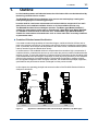
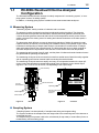
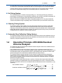
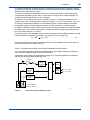
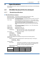
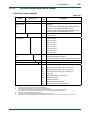
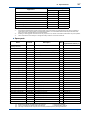
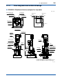
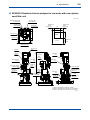
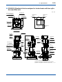
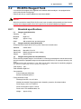
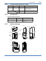
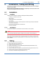
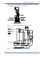
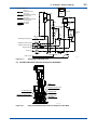
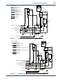
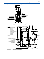
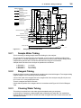
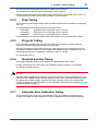
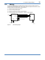
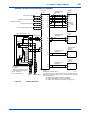
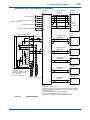
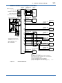
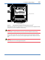
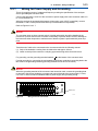
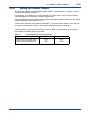

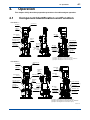
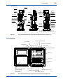
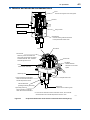
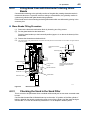
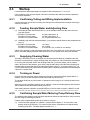
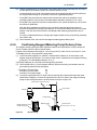
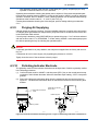
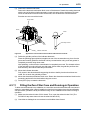
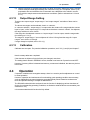

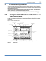
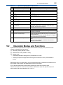
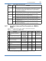
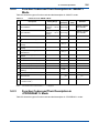
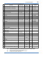
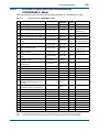
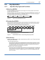
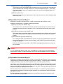
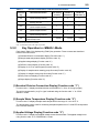
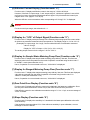
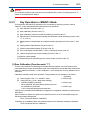
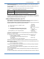
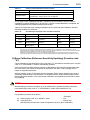
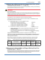
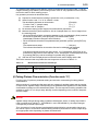
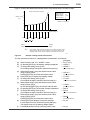
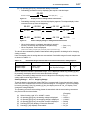
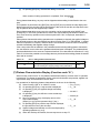
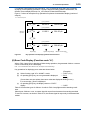
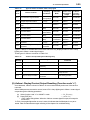
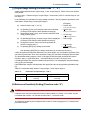
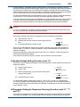
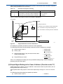
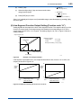
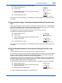
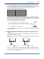
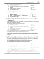
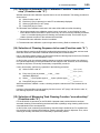
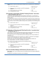
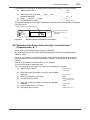
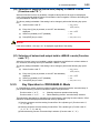
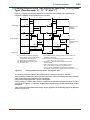
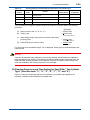
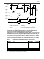
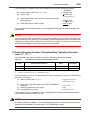
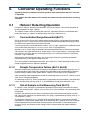
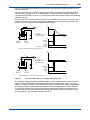
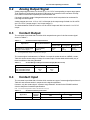
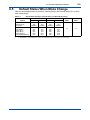

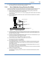
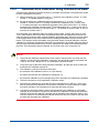
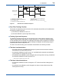
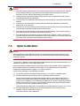
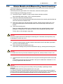
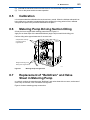
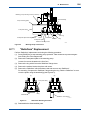
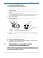
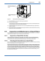
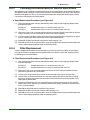

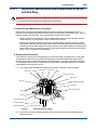
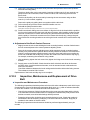
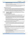
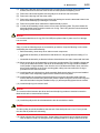
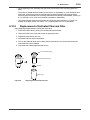
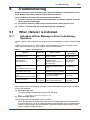
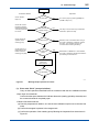
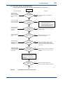
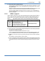
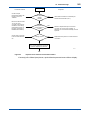
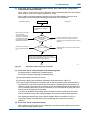
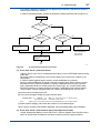
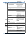
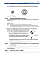
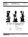
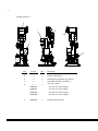
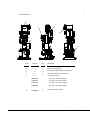
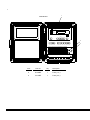
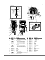
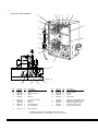
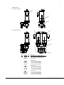
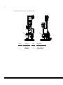
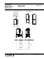

![RC400G 残留塩素計[スタイル:S3]](http://vs1.manualzilla.com/store/data/006664404_2-a03d043413d751c58d3c99263891269a-150x150.png)