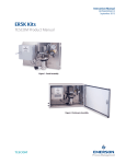
1
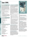
For optimal performance in your application, the calibration of
the Type 2000 can be fine-tuned in the field. An easilyremovable cover provides access to the isolated electronics.
All potentiometers, connections, jumpers, and switches are
clearly marked on the circuit board or on the handy chart
located on the inside of the cover. The three elements of calibration (Gain, Zero, and Span) are described below. Consult
the Type 2000 User’s Manual for detailed calibration procedures, cautions, and instrumentation requirements.
Onboard switches allow the user to easily reconfigure the
Type 2000 for any of several electrical inputs, direct/reverse
acting, or output split-ranging high/low. Fine tuning of the
unit’s calibration may be necessary after a reconfiguration.
GAIN (DAMPING)
ADJUSTMENT
SPLIT RANGING
HIGH & LOW
The Type 2000 contains multi-turn Coarse-Zero, Fine-Zero,
and Span adjustment potentiometers which are clockwise
positive. Adjustment of either Zero Pot changes the unit’s
minimum output while the Span Pot changes the maximum
output. The adjustments are interactive, so it may take
iterations to reach the desired calibration.
WIDE RANGEABILITY
The Type 2000 can be field calibrated to pressure ranges
other than the standard ones by combinations of recalibration, pressure range switching, and split high/low ranging. A
unit should not be switched to a range outside its pressure
sensor family (eg., a 0-15 psig can be switched to a 3-15 psig,
but not to 0-30 psig). (Caution: Do not exceed the range of the
onboard pressure sensor.) For example, the easiest way to
recalibrate a 0-30 psig unit to 3-15 psig would be to change
the switch setting to 3-27 psig , then switch to split range low.
4.780
3.883
Direct Acting transducers regulate to their minimum output
when supplied with minimum input; maximum out with
maximum in. Reverse Acting transducers regulate to their
maximum output at minimum input.
The Type 2000 can be configured to regulate either half (top
or bottom) of it’s normal output range, when supplied with it’s
normal full-ranging electrical input. For example, a 0-10V 030psi unit set to split range low will regulate 0-15psi @ 0-10V.
It will regulate 15-30psi @ 0-10V if set to split range high.
HAZARDOUS AREA &
USAGE CLASSIFICATION
INTRINSIC SAFETY: (S Enclosure) Factory Mutual
approvals: Class I, II, and III, Divisions 1 and 2, Groups A
through G. ATEX Approvals:
II 1 G EEx ia IIC T4 (20˚C<Ta<+60˚C)
NEMA 4X / IP66: (Conduit and Hirschmann Connectors only)
Water tight, dust tight, and corrosion resistant.
EXPLOSION PROOF: (E Enclosure; N Electrical Port; G
Agency Approval) Certified to CSA standards. Class I,
Division 1, Groups C and D, T3. Exia IIB Ci=0, Li=0, 24VDC,
25MA. Meets the requirements for CSA Class I Division 1,
Group D gas use, including natural gas as the media flowing
through the transducer.
CE: (Conduit Connector Only) EN 50081-1 Residential, commercial & light industry; EN-50082-2 Heavy Industrial.
EASY ACCESS TOP COVER
1) Isolated electronics
2) Calibration adjustments
3) Configuration switches
4) Switch information on inside of cover
MOUNTING OPTIONS
1) In-Line
2) Direct: Holes on left rear
and bottom faces
3) Bracket Mounting options:
Panel, pipe, valve, DIN-rail
ELECTRICAL PORT
OPTIONS
1) 1/2" NPT Conduit
2) 20mm Conduit
3) Hirschmann (DIN 43 650-A)
4) Terminal Block
EASY ACCESS ORIFICE
OUTPUT PORT
Same as Input Port
(Not shown; rear face)
INTEGRAL BOOSTER
Flows up to 21 SCFM
for quick system response
GAUGE PORT
1/8" NPT on all models
MANIFOLD-MOUNTING OPTION
Supply and Output ports on the bottom
face rather than “through the body”
INPUT PORT OPTIONS
1) 1/4" NPT
2) 1/4" BSPP
3) 1/4" BSPT
2X M3X0.5
X .250 DEEP
2X 8-32 UNC-2B
X .375 DEEP
MOUNTING HOLES
DIRECT/REVERSE ACTING
OUT
1.893
IN
.570 TYP
T-2000 DIMENSIONAL DRAWINGS
ZERO & SPAN
ADJUSTMENTS
.360
.716
T-2000 I/P & E/P TRANSDUCERS
The output response of the Type 2000 can be optimized for
varying downstream volumes by adjusting the system gain of
the control circuit. Adjust the Gain Pot counterclockwise for
increased gain; clockwise for increased oscillation damping.
For maximum allowable gain in your application, the pot
should be turned clockwise until oscillation just disappears.
1/2-14 NPT
FIELD-SELECTABLE
FEATURES
.550
1.060
1/4-18 NPT TYP
1.100
TYPE 2000
Marsh
Bellofram
FINE-TUNING YOUR
APPLICATION
1.37
[34.7]
2.307
2.225
2.939
3.92
1.10
[99.5]
[27.9]
0.55
[14.0]
TYPE 2000 EXPLOSION PROOF
Drawings and dimensions are
for reference only.
6.01
[152.6]
2.06
1.78
OUT
[52.3]
[45.2]
0.68
[17.3]
2.12
0.57
[14.5]
[53.8]
USA
EUROPE
State Route 2, Box 305
9 Castle Park, Queens Drive
Newell, WV 26050
Nottingham NG2 1AH, UK
800-727-5646 or (304) 387-1200 Tel +44 (0) 115 993 3300
FAX (304) 387-4417
Fax +44 (0) 115 993 3301
[email protected]
[email protected]
SALES & APPLICATIONS
(800)727-5646 fax:(304) 387-4417
LT1025 3m 11/03
www.marshbellofram.com
IMPORTANT NOTICE
Our recommendations, if any, for the use of this product are based on tests believed
to be reliable. The greatest care is exercised in the selection of our raw materials and
in our manufacturing operations. However, since the use of this product is beyond
the control of the manufacturer, no guarantee or warranty, express or implied is made
as to such use or effects incidental to such use, handling or possession or the results
to be obtained, whether in accordance with the directions or claimed so to be. The
manufacturer expressly disclaims responsibility therefor. Furthermore, nothing
contained herein shall be construed as a recommendation to use any product in
conflict with existing laws and/or patents covering any material or us.
DESCRIPTION
SPECIFICATIONS
ACCURACY
ELECTRICAL
Inputs
Connections
Power Supply
Direct/Reverse Acting
PNEUMATIC
Outputs
Ports (Input/Output)
Exhaust
(Explosion proof only)
Ports (Gauge)
Supply
Split-Ranging
Consumption
Flow Capacity
PRINCIPLE OF OPERATION
APPLICATIONS
The Type 2000 I/P and E/P transducers utilize closed-loop pressure
feedback-control for precision pressure output and minimized
effects of temperature, supply pressure changes, supply voltage
changes, and mounting angle.
Supply pressure is reduced by the supply valve to provide an
output pressure which is internally routed to a precision temperature compensated piezoresistive pressure sensor. Supply
pressure is also routed to an externally removable orifice which
provides a reduced pilot pressure to a chamber containing a servo
diaphragm and nozzle. Pilot pressure is controlled by modulating
the gap between the face of a nozzle and an adjacent
piezo-ceramic actuator, which is part of a unique patented
mechanism.
The piezo-ceramic actuator serves as a control link between electrical input and
pressure output as follows:
• The input current (I/P) or voltage (E/P) signal is conditioned to provide a normalized control signal directly proportional to the desired pressure output.
• Simultaneously the output of the pressure sensor is amplified and conditioned to
produce a feedback signal.
• The sum of the control signal and the feedback signal produce a command
signal which is delivered as a DC voltage to the piezo-ceramic actuator.
• As voltage increases, the force applied by the actuator increases, so as to
restrict nozzle bleed and thus increase pilot pressure.
• Increased pilot pressure applied to the servo diaphragm directly causes opening
of the supply valve and an increase in the output pressure until the output
feedback signal and control signal combine to produce the correct command
signal.
The Type 2000’s precisely
regulated pneumatic output can
be used to operate:
• Valve actuators
• Louver and damper actuators
• Valve positioners
• Relays
• Clutches and brakes
• Controllers
• Air cylinders
INDUSTRY APPLICATIONS INCLUDE:
• Chemical & Petrochemical Industries
• Petroleum Production
• Pipeline Transmission
• Electric Utilities
• Water & Wastewater Systems
• Pulp & Paper
• Textiles
• Semiconductor Industry
• Food & Beverage
• Environmental Control Systems
• Construction Equipment
• Agricultural Equipment
• Machine Tool
• Material Handling
• Automotive Testing & Assembly
• Medical Equipment
ORDERING INFORMATION
0.1% of full-scale output typical (0.25% guaranteed);
includes effects of hysteresis, dead band, and repeatability
Exhaust Capacity
Series
2
Switch-Selectable
4-20mA. 0-5, 1-5, 1-9, 1-10, or 0-10VDC
1/2" NPT or 20mm Conduit
DIN Hirschmann (S model only)
External Terminal Block (S model only)
5-28VDC (with voltage inputs only)
Switch-Selectable
70
4.8
60
4.1
50
3.4
40
2.8
30
2.1
20
1.4
10
0.7
0 0
SCFM 0
LPM 0
-
Specials
-
0
TYPE 2000
EXPLOSION PROOF
0
ACCESSORIES
P/N
Electrical Port
N = 1/2" NPT Conduit
M = 20mm Conduit
H = Hirschmann
T
= Terminal Block 2
1/4" (NPT, BSPT, or BSPP threads)
Bottom-ported for Manifold Mounting
1/8"-27 NPT
Panel Mounting Kit
010-135-000
Valve Mounting Kit
010-134-000
2" Pipe Mounting Kit
010-143-000
(Valve Mounting Kit is required)
Pneumatic Ports
N = NPT
T
= BSPT
P
= BSPP
M = Manifold Mount 3
DIN Rail Adapter
010-115-000
Manifold Adapter Kit
971-158-000
Filter Kit, 60 microns
010-139-000
Filter Kit, Coalescing,
0.1 microns
010-140-000
Filter Element Kit
010-141-000
(for coalescing filter, package of 10)
Pressure Gauge Kit
Agency Approval
F
= FM/CSA
C = ATEX
G
= Certified to CSA
Standards 4
N = None
010-138-000
15 psig (1 BAR)
Pressure Gauge Kit
010-138-001
30 psig (2.1 BAR)
Pressure Gauge Kit
010-138-002
60 psig (4.1 BAR)
42
05
15
19
11
01
=
=
=
=
=
=
4-20 mA
0-5 V
1-5 V
1-9 V
1-10 V
0-10 V
D
R
= Direct Acting
= Reverse Acting
F
H
L
= Full Range
= Split Range High
= Split Range Low
Pressure Gauge Kit
010-138-003
160 psig (11 BAR)
NOTES:
1
Availability Matrix
N
Electrical
M
Port
H
T
Enclosure
S
E
yes yes
yes yes
yes
no
yes
no
2
None
None
<1%FS (+/-1G; 5-1000Hz)
0.02%FS/˚F (-40˚ to 180˚F [-40˚ to 82˚C])
None
MOUNTING OPTIONS
CE-compliant
-40˚ to 200˚F (-40˚ to 93˚C)
Mounting Method Intrinsically-Safe (S) Model Explosion-Proof (E) Model
In-Line
Yes
Yes
TYPE 2000: REGULATED PRESSURE VS. FLOW
Direct Mounting
Side or Bottom Holes
Side or Bottom Holes
140 psig supply pressure
Panel Bracket
Supplied
Accessory
Valve Bracket
Accessory
Supplied
Pipe Bracket
Accessory
Accessory
DIN-Rail Bracket
Accessory
Accessory
Manifold Plate
Accessory
Accessory
MOUNTING: The Type 2000 can be mounted in-line, or directly to a panel via
mounting holes located in the side and bottom of the unit. In addition, the S
model includes a panel-mounting bracket; while the E model includes a valvemounting bracket. Kits are available for mounting of either model to panel,
2 4
6
8 10 12 14 16 18 20 22 24 valve, pipe, or DIN-Rail. A custom plate is available for mounting of the
57 113 170 227 283 340 397 453 510 566 623 680
bottom-ported version to a manifold. (See Accessories)
Forward Flow
w w w. m a r s h b e l l o f r a m . c o m
-
Pneumatic Output
1
STABILITY
Supply Voltage Effect
Supply Pressure Effect
Vibration Effect
Temperature Effect
Mounting Position Effect
RFI/EMI
Storage Temperature
psig BAR
K
Electrical Input
Enclosure
S
= Intrinsically Safe
E
= Explosion Proof
0-2, 0-5, 0-15, 3-15, 1-17, 0-30, 6-30, 3-27, 0-60, 0-100, or 120 psig
0-0.1, 0-0.3, 0-1.0, 0.2-1.0, 0.07-1.2, 0-2.1, 0.4-2.1, 0.2-1.9,
0-4.1, 0-6.9, 0-8.3 BAR
1/8" NPT
From 5 psi (0.3 BAR) above output, up to
140 psi (9.7 BAR) maximum (20 psi [1.4 BAR] minimum)
Switch-Selectable, Full-Range or
Split-Range High or Split-Range Low
4 scfh maximum (1.9 LPM)
RANGE
SENSOR
FLOW
psig
BAR
psig BAR
scfm LPM
0-2
0-0.1
2
0.1
4
113
0-5
0-0.3
5
0.3
11
312
0-15
0-1.0
15
1.0
19
538
3-15
0.2-1.0
15
1.0
19
538
1-17
0.07-1.2 15
1.0
19
538
0-30
0-2.1
30
2.1
21
595
3-27
0.2-1.9
30
2.1
21
595
6-30
0.4-2.1
30
2.1
21
595
0-60
0-4.1
50
3.5
21
595
0-100 0-6.9
100 6.9
21
595
0-120 0-8.3
100 6.9
21
595
(Typical Flow @ 140 psi (9.7 BAR) in and maximum out)
3 SCFM (85 LPM) @ 5 psig (0.3 BAR) above setpoint
(0-15 psig range unit set at mid range)
Model
800-727-5646
002
005
015
315
117
030
630
327
060
100
120
00
=
=
=
=
=
=
=
=
=
=
=
NEMA 4X / IP66 not available
Bottom O-Ring Ports
0-2 psig
0-0.1 BAR
0-5 psig
0-0.3 BAR
0-15 psig
0-1.0 BAR
3-15 psig 0.2-1.0 BAR
1-17 psig 0.07-1.2 BAR
0-30 psig
0-2.1 BAR
6-30 psig 0.4-2.1 BAR
3-27 psig 0.2-1.9 BAR
0-60 psig
0-4.1 BAR
0-100 psig 0-6.9 BAR
0-120 psig 0-8.3 BAR
3
4
Including Natural Gas Use (E
Enclosure; N Electrical Port)
= None
Terminal Block
S
+
-
WIRING CONNECTIONS
AND SWITCH POSITIONS
Switch # 1: psig
ON
0-2
0-15
3-15
1-17
0-30
3-27
6-30
0-100
Switch # 1: psig
OFF
0-60
0-120
BAR
0-0.3
0-1.0
0.2-1.0
0.07-1.2
0-2.1
0.2-1.9
0.4-2.1
0-6.9
BAR
0-4.1
0-8.3
I/P Transducer
N/C
+ Signal
- Signal
E/P Transducer
+ Signal
+Power Supply
Common
2
1-5 VDC
0-5 VDC
3
Split Low
4
Voltage
Input
(E/P)
5
Full
Split Low
6: psig
0-2
0-15
1-17
0-30
0-60
0-100
0-120
BAR
0-0.3
0-1.0
0.07-1.2
0-2.1
0-4.1
0-6.9
0-8.3
7
Reverse
Acting
8
Full
9
I/P
2
1-9 VDC
1-10 VDC
4-20 mA
3
Full
Split High
4
Current
Input (I/P)
5
Split High
6: psig
3-15
3-27
6-30
BAR
0.2-1.0
0.2-1.9
0.4-2.1
7
Direct
Acting
8
Split Low
Split High
9
E/P
TYPE 2000 SPECIFICATIONS
TYPE 2000 I/P & E/P TRANSDUCERS
The Marsh Bellofram Type 2000 is a robust electronic instrument that regulates an incoming
supply pressure down to a precise output pressure
which is directly proportional to an electrical
control signal. The secret to the Type 2000’s
precise, reliable performance under a variety of
demanding environmental conditions is a patented
piezo-ceramic actuator with many industry-wide
firsts.
The Type 2000 has been designed to meet the
electropneumatic needs of the world:
• Field-selectable inputs and direct/reverse/split
ranging
• Multiple input/output/mounting configurations
• Precise, reliable performance under extreme
conditions of temperature, vibration, orientation, supply pressure changes, supply voltage
changes, RFI/EMI, humid / oilladen media, and corrosive
surroundings
For optimal performance in your application, the calibration of
the Type 2000 can be fine-tuned in the field. An easilyremovable cover provides access to the isolated electronics.
All potentiometers, connections, jumpers, and switches are
clearly marked on the circuit board or on the handy chart
located on the inside of the cover. The three elements of calibration (Gain, Zero, and Span) are described below. Consult
the Type 2000 User’s Manual for detailed calibration procedures, cautions, and instrumentation requirements.
Onboard switches allow the user to easily reconfigure the
Type 2000 for any of several electrical inputs, direct/reverse
acting, or output split-ranging high/low. Fine tuning of the
unit’s calibration may be necessary after a reconfiguration.
GAIN (DAMPING)
ADJUSTMENT
SPLIT RANGING
HIGH & LOW
The Type 2000 contains multi-turn Coarse-Zero, Fine-Zero,
and Span adjustment potentiometers which are clockwise
positive. Adjustment of either Zero Pot changes the unit’s
minimum output while the Span Pot changes the maximum
output. The adjustments are interactive, so it may take
iterations to reach the desired calibration.
WIDE RANGEABILITY
The Type 2000 can be field calibrated to pressure ranges
other than the standard ones by combinations of recalibration, pressure range switching, and split high/low ranging. A
unit should not be switched to a range outside its pressure
sensor family (eg., a 0-15 psig can be switched to a 3-15 psig,
but not to 0-30 psig). (Caution: Do not exceed the range of the
onboard pressure sensor.) For example, the easiest way to
recalibrate a 0-30 psig unit to 3-15 psig would be to change
the switch setting to 3-27 psig , then switch to split range low.
4.780
3.883
Direct Acting transducers regulate to their minimum output
when supplied with minimum input; maximum out with
maximum in. Reverse Acting transducers regulate to their
maximum output at minimum input.
The Type 2000 can be configured to regulate either half (top
or bottom) of it’s normal output range, when supplied with it’s
normal full-ranging electrical input. For example, a 0-10V 030psi unit set to split range low will regulate 0-15psi @ 0-10V.
It will regulate 15-30psi @ 0-10V if set to split range high.
HAZARDOUS AREA &
USAGE CLASSIFICATION
INTRINSIC SAFETY: (S Enclosure) Factory Mutual
approvals: Class I, II, and III, Divisions 1 and 2, Groups A
through G. ATEX Approvals:
II 1 G EEx ia IIC T4 (20˚C<Ta<+60˚C)
NEMA 4X / IP66: (Conduit and Hirschmann Connectors only)
Water tight, dust tight, and corrosion resistant.
EXPLOSION PROOF: (E Enclosure; N Electrical Port; G
Agency Approval) Certified to CSA standards. Class I,
Division 1, Groups C and D, T3. Exia IIB Ci=0, Li=0, 24VDC,
25MA. Meets the requirements for CSA Class I Division 1,
Group D gas use, including natural gas as the media flowing
through the transducer.
CE: (Conduit Connector Only) EN 50081-1 Residential, commercial & light industry; EN-50082-2 Heavy Industrial.
EASY ACCESS TOP COVER
1) Isolated electronics
2) Calibration adjustments
3) Configuration switches
4) Switch information on inside of cover
MOUNTING OPTIONS
1) In-Line
2) Direct: Holes on left rear
and bottom faces
3) Bracket Mounting options:
Panel, pipe, valve, DIN-rail
ELECTRICAL PORT
OPTIONS
1) 1/2" NPT Conduit
2) 20mm Conduit
3) Hirschmann (DIN 43 650-A)
4) Terminal Block
EASY ACCESS ORIFICE
OUTPUT PORT
Same as Input Port
(Not shown; rear face)
INTEGRAL BOOSTER
Flows up to 21 SCFM
for quick system response
GAUGE PORT
1/8" NPT on all models
MANIFOLD-MOUNTING OPTION
Supply and Output ports on the bottom
face rather than “through the body”
INPUT PORT OPTIONS
1) 1/4" NPT
2) 1/4" BSPP
3) 1/4" BSPT
2X M3X0.5
X .250 DEEP
2X 8-32 UNC-2B
X .375 DEEP
MOUNTING HOLES
DIRECT/REVERSE ACTING
OUT
1.893
IN
.570 TYP
T-2000 DIMENSIONAL DRAWINGS
ZERO & SPAN
ADJUSTMENTS
.360
.716
T-2000 I/P & E/P TRANSDUCERS
The output response of the Type 2000 can be optimized for
varying downstream volumes by adjusting the system gain of
the control circuit. Adjust the Gain Pot counterclockwise for
increased gain; clockwise for increased oscillation damping.
For maximum allowable gain in your application, the pot
should be turned clockwise until oscillation just disappears.
1/2-14 NPT
FIELD-SELECTABLE
FEATURES
.550
1.060
1/4-18 NPT TYP
1.100
TYPE 2000
Marsh
Bellofram
FINE-TUNING YOUR
APPLICATION
1.37
[34.7]
2.307
2.225
2.939
3.92
1.10
[99.5]
[27.9]
0.55
[14.0]
TYPE 2000 EXPLOSION PROOF
Drawings and dimensions are
for reference only.
6.01
[152.6]
2.06
1.78
OUT
[52.3]
[45.2]
0.68
[17.3]
2.12
0.57
[14.5]
[53.8]
USA
EUROPE
State Route 2, Box 305
9 Castle Park, Queens Drive
Newell, WV 26050
Nottingham NG2 1AH, UK
800-727-5646 or (304) 387-1200 Tel +44 (0) 115 993 3300
FAX (304) 387-4417
Fax +44 (0) 115 993 3301
[email protected]
[email protected]
SALES & APPLICATIONS
(800)727-5646 fax:(304) 387-4417
LT1025 3m 11/03
www.marshbellofram.com
IMPORTANT NOTICE
Our recommendations, if any, for the use of this product are based on tests believed
to be reliable. The greatest care is exercised in the selection of our raw materials and
in our manufacturing operations. However, since the use of this product is beyond
the control of the manufacturer, no guarantee or warranty, express or implied is made
as to such use or effects incidental to such use, handling or possession or the results
to be obtained, whether in accordance with the directions or claimed so to be. The
manufacturer expressly disclaims responsibility therefor. Furthermore, nothing
contained herein shall be construed as a recommendation to use any product in
conflict with existing laws and/or patents covering any material or us.


![RC400G Residual Chlorine Analyzer [Style: S3]](http://vs1.manualzilla.com/store/data/005893183_1-484cd185856d4428f9cc01b01a19e45f-150x150.png)