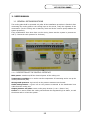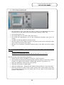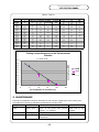
1
Date: 8/25/2004
TS-CV-DC
TS/CV Detector Cooling Project Document No./MP5 No
127.50/FCUL-00009
CERN
CH-1211 Geneva 23
Switzerland
EDMS Document No.
452100
TECHNICAL FOLDER
CMS TRACKER PORTABLE COOLING UNIT
MP5: FCUL-00009
General description and functionalities
This portable cooling unit runs a mixture of water and ethylene glycol, cooled down by a
scroll compressor refrigerating unit.
The maximum cooling power is 4.5 kW @ -25°C, corresponding to a total flow rate of
1.1 m3/h, for a nominal pressure of 5 bar (~1kW @ -20°C on the distribution lines).
Three distribution lines serve the user circuits.
Prepared by :
Checked by :
Stephane Berry
Florian Corbaz
Paola Tropea
TS/CV
[email protected]
1/6
TS-CV-DC Project Document No./ MP5 No
127.50/FCUL-00009
1. USER MANUAL
1.1 GENERAL RECOMMENDATIONS
The cooling plant shall be operated only after all the installation procedure is finished. After
connecting the cooling plant to the cooling loops to be served, verify the tightness of the
connections. (Put the cooling unit in Stand-by mode and let the vacuum pump stabilize the
system pressures).
If big modifications have been done on the circuit, please test the system in pressure as
well (1.5 times the work pressure for 24 hours).
1.1.1 DESCRIPTION OF THE CONTROL INTERFACE
Main power: switches on/off the electrical power of the cooling unit
Temperature regulator: it is used to set the temperature of functioning and to set-up the
control parameters (PID)
Storage tank pressure: it gives info on the pressure measure into the tank
Outlet tank pressure: it gives info on the pressure measured at the distribution lines
outlet form the cooling unit
Output pressure set-point: it acts on the pump inverter (1 turn = about 1 bar)
Control: it is used to switch the cooling unit between the stop/stand-by/run status, to read
the alarms and to re-boot the system.
2/6
TS-CV-DC Project Document No./ MP5 No
127.50/FCUL-00009
1.2 STARTING PROCEDURE
Before starting the cooling unit, the user must check:
•
the connections to the user pipes are tight (3 valves on the distribution lines serve
the three lines to the panels of the environmental chamber in bldg. 186)
•
the electrical power is on
•
the cooling plant is in the “OFF” mode (PLC screen)
•
the correct set temperature is set on the Temperature regulator (see §5.2.1 for
details)
•
no alarms or warning appear on the PLC screen
•
that the pump inverter (Output pressure set-point) is turned on the minimum value
(turn counter clock wise until it stops)
•
that the dry air flushing is activated (manual valve on the back side of the cooling
rack)
N.B.: for the actual installation, some checks have to be done also on the environmental
chamber:
-
open the distribution circuit valves
-
open the dry air distribution into the cold box (flow rate of 5 to 10 m3/h)
After the checks, these steps shall be followed:
•
change the PLC status in STAND-BY (push the + sign on the PLC)
•
wait for about 20 minutes and check regularly that the pressure in the tank is stable
at about 700 mbara (check that the “storage tank pressure” is at about -0.3)
•
Open the distribution valves (if they were closed)
•
Wait until the pressure is stable again
•
Start the cooling plant : change the PLC status in RUN (push the + sign on the PLC)
•
Raise the pressure by mean of the inverter (knob of the “outlet pressure set-point”
to be turned clock wise) up to an outlet vale of 2 bar (check on the “outlet tank
pressure” manometer)
3/6
TS-CV-DC Project Document No./ MP5 No
127.50/FCUL-00009
1.2.1 SET OF THE DISTIRBUTION TEMPERATURE
To change the temperature at the distribution line:
•
push the “*” on the temperature regulator
•
wait for the actual temperature set point to be shown keeping the button pushed
•
adjust the set-point by using the flashes (always keeping the “*” button pushed)
•
Release all buttons
PLEASE NOTE THAT THE PARAMETERS OF THE REGULATOR HAVE BEEN SET FOR AN
OPTIMAL USE OF THE COOLING PLANT AT -20°C. IN CASE YOU NEED BIG CHANGES IN
THE DISTRIBUTION TEMPERATURE, PLEASE FORESEE AN INTERVENTION FOR THE
REGULATOR PARAMETER TUNING
1.3 ALARM LIST & ACTIONS
Alarm
Low pressure on fridge unit
Signal generator
Pressure switch
High pressure on fridge unit
Pressure sitch
Low liquid level
Level meter
Regulator alarm
+60°C)
Overheating
(T>
Tset Regulator
High pressure in the tank
Thermostat du chauffage
Pressure switch HP on tank
Vacuum pump : pumping Pressure switch LP on tank
time longer than 10 min
Power failure
PLC
Action
Call for intervention (possible leak into the
fridge circuit)
Call for intervention (possible leak into the
fridge circuit)
Check for liquid leaks, eventually fill the
tank (if during the filling of the circuits)
Call for intervention – leave the plant in
stand-by mode
Call for intervention – leave the plant in
stand-by mode
Re-start the plant in stand-by mode and
verify the tightness
Check for leaks on the return line
Run the start up procedure
Call for intervention: Paola Tropea tel 164999
1.4 STOP PROCEDURE
To stop the cooling unit:
•
Lower down the pump pressure (turn the “output pressure set-point” knob counter
clock wise until it stops and pressure on the “outlet tank pressure” manometer is 0)
•
Change the status in STAND-BY (push the - sign on the PLC)
•
Change the status in STOP (push the - sign on the PLC)
•
Close the distribution valves
4/6
TS-CV-DC Project Document No./ MP5 No
127.50/FCUL-00009
2. TEST
2.1 PERFORMANCE TESTS IN THE LABORATORY
The parameters listed in §4.5 have been established after testing of performances in the
TS/CV/DC laboratory, by Stephane Berry and Paola Tropea.
A dummy load of 6 kW has been used to evaluate the cooling unit performances.
The set point temperature for the actual parameters of the temperature regulator is -20°C.
At this temperature, the cooling power of the plant is 1kW.
2.2 PERFORMANCE TESTS ON THE USER INSTALLATION (CMS
ENVIRONMENTAL CHAMBER IN BLDG. 186 – AUGUST 04)
The three lines serving the cold box panels are connected and filled. The cold box is flushed
in a continuous way by dry air. The ambient temperature varies between 20 and 28°C
during the tests.
The performances of the cooling unit listed in the table below correspond to these particular
ambient condition and hydraulic connection. In particular, Test A has been performed with
an average ambient temperature of 26°C, and Test B has been performed with an average
ambient temperature of 22 °C.
In the following tables, “T measured” corresponds to the temperature measured
downstream the heat exchanger by the PT100 used as feedback signal for the electrical
heater.
The “electrical power” corresponds to the percentage of the electrical heater which is used
to maintain the set-temperature and gives the order of magnitude of the cooling power of
the cooling unit which is available at that temperature for other heat than that produced by
the empty environmental chamber flushed with dry air.
Table 1: TEST A
TIME
hh:mm
10:50
14:00
17:10
20:00
8:00
11:00
T set point
°C
0
-5
-10
-15
-10
-20
Cooling Plant
T measured
El. power
°C
% of 4.5 kW
-1.6
-4.9
-10
45
-15.1
20
-10
53
-20
2
El. power
kW
2.0
0.9
2.4
0.1
5/6
Environmental Chamber
T1
T2
RH
°C
°C
%
11.8
9.8
29
6.8
4.4
20
2.5
-0.1
20
-2.1
-5.1
-0.8
-1.4
20
-8.2
-5.4
--
TS-CV-DC Project Document No./ MP5 No
127.50/FCUL-00009
Table 2: TEST B
Time
HH:MM
9:21
9:30
15:35
15:36
8:30
10:10
10:11
12:25
14:30
14:40
18:00
18:05
19:05
18:55
8:37
Ambient
T
°C
T set-point
°C
23.2
23.2
20.1
20.0
20.0
23.0
24.0
24.0
22.0
22.0
22.0
23
20
0
0
-5
-5
-5
-10
-10
-10
-15
-15
-20
-20
-20
-20
Cooling Plant
T measured El. power
°C
% of 4.5 kW
23.2
Environmental Chamber
T1
T2
RH
°C
°C
%
24.3
24.6
41
El. power
kW
-2.6
98
4.41
7.6
5.8
20
-5.0
-5.0
86
88
3.87
3.96
4.5
4.4
2.5
2.1
20
20
-9.9
-10.0
52
50
2.34
2.25
1.9
1.6
-0.9
-1.1
20
1
-15.0
26
1.17
-2.4
-5.4
-
-19.8
-20.1
-20.1
0
2
6
0.00
0.09
0.27
-4
-5.7
-6.7
-7.2
-8.9
-9.6
-
Cooling unit performances on the Environmental
Chamber
y = 0.25x + 5.00
5.0
4.5
Cooling Power [kW]
4.0
3.5
3.0
2.5
2.0
1.5
1.0
Test B
Test A
0.5
0.0
0
-5
-10
-15
-20
-25
Set Temperature on Controller [°C]
3. MAINTENANCE
Preventive maintenance must be foreseen for some of the equipments of the cooling unit.
The table below shows an indicative maintenance procedure list:
Equipment
Condition
Action
Spare
Pump
After 1 year
Check of the shaft seal (presse
etoupe) – ev. Change
Shaft seal (to be
bought)
Filter
After 1 year
Clean the filter
-
Connections
After 1 year
Check
the
connections
6/6
tightness
of
the
-