1
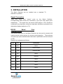
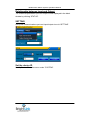
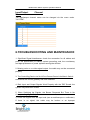
Multifunction Matrix System
Operations Manual
V6.5
RGB Matrix Switcher
VGA Matrix Switcher
Audio & Video Matrix
Switcher
HDMI Matrix Switcher
Brightlink Cables LLC
1409 S Lilac Ave BLOOMINGTON,
CALIFORNIA 92316, UNITED STATES
TOLL FREE: 1-855-44 WIRED (94733)
www.brightlinkcables.com
For optimum performance and safety, please read these instructions carefully before
connecting, operating or adjusting this product. Please keep this manual for future
reference.
Multifunction Matrix System Operation Manual
Safety Precautions
For the sake of safety and proper equipment installation, operation, and
maintenance, the following guidelines are provided and should be perused
and followed for this unit:
•
Use single-phase, three-wire/split-phase electric power and ensure
grounding for the entire system. Attach the matrix to true ground and
ensure ground resistance is less than one (1) Ohm.
Do not use a
non-ground power supply and make sure the ground wire is intact.
Without
proper
grounding,
signal
interference,
performance
instability, and electric shock may occur.
•
Do not use a two-pin plug. The power supply must be 220VAC
50Hz.
•
Turn off all power sources when relocating the units, or when
performing any operational/maintenance activities.
•
The unit contains a 220V high voltage assembly.
Please do
not disassemble it or repair it without a professional’s permission to
avoid damages, unit degradation, or accidental mishaps.
•
The unit should be powered off during plugging or un-plugging to
avoid short circuiting.
Any resulting damages will not be covered by
the equipment warranty.
•
Temperature, humidity and dust may affect the performance of the
unit.
•
Do not apply pressure to the unit to avoid damage.
•
Refer to this manual with queries. Contact us directly for additional
comment and questions.
1
Multifunction Matrix System Operation Manual
Table of content
1. ABOUT THE MATRIX SWITCHER................................................3
1.1. RGB MATRIX SWITCHER .............................................................3
1.2. VGA MATRIX SWITCHER .............................................................3
1.3. AUDIO&VIDEO MATRIX SWITCHER ............................................4
1.4. HDMI MATRIX SWITCHER ...........................................................5
2. EQUIPMENT ITEMS......................................................................5
3. INSTALLATION .............................................................................6
4. RS232 SERIAL COMMUNICATION PROTOCOL.........................7
5. OPERATION ..................................................................................9
5.1. STANDBY MODE.....................................................................9
5.2. SWITCH KEY ..........................................................................10
5.3. FUN KEY .................................................................................10
5.4. SOFTWARE........................................................................... 11
6. TROUBLESHOOTING AND MAINTENANCE ............................14
7. SPECIFICATION..........................................................................15
7.1. RGB&VGA SWITCHER SPECIFICATION......................................15
7.2. AUDIO&VIDEO SWITCHER SPECIFICATION ..............................16
7.3. HDMI SWITCHER SPECIFICATION ..............................................17
2
Multifunction Matrix System Operation Manual
ABOUT THE MATRIX SWITCHER
1.1. RGB Matrix Switcher
RGB Matrix Switcher is used for routing and distributing RGBHV and
component video signals.
multiple destination.
It routes multiple source of RGBHV signals to
It is high efficiency video-signal routing equipment
which can be used for various video signals and to supply individual
component video input and output signals.
The components of a video
signal are transmitted and routed as separated signals to avoid interference
to maintain the signal clarity.
RGB Matrix Switcher contains a high performance and variable gain
technology processor.
Each amplified output parameter can be adjusted
separately. Digital tuning is also. A disadvantage: (1) the video image can
be affected by the length of cable (video appears too dark with long cable
and too bright with short cable).
A
buffered circuit and frequency
compensation ensures signal clarity and transmission stabilization for
transmitting over longer distances. The unit is equipped with short circuit
protection, LCD display, embedded intelligent system, RS232 port, RJ-45
port (optional), and the capability to work with various remote control
devices.
The unit can be used in different aspects, e.g. TV broadcast; media
conference room; big screen advertising; education and training; data
control center; and, other instances requiring multiple routing technology.
1.2. VGA Matrix Switcher
VGA Matrix Switcher is used for routing and distributing VGA signals.
The
unit routes multiple sources of VGA signals to multiple destination.
The
high efficiency video-signal routing equipment can be used for various video
signals and to supply individual component video input and output signals.
The components of a video signal are transmitted and routed as distinct
signals to mitigate signal interference and to maintain the signal clarity.
3
Multifunction Matrix System Operation Manual
VGA Matrix Switcher contains a high performance and variable gain
technology processor.
Each amplified output parameter can be adjusted
separately and supports digital tuning.
A disadvantage: (1) the video
image can be affected by the length of cable (video appears too dark with
long cable and too bright with short cable).
frequency
compensation
ensures
signal
A buffered circuit and
clarity
and
transmission
stabilization for transmitting over longer distances. The unit is equipped
with short circuit protection, LCD display, embedded intelligent system,
RS232 port, RJ-45 port (optional), and the capability to work with various
remote control devices.
The unit can be used in different aspects, e.g. TV broadcast; media
conference room; big screen advertising; education and training; data
control center; and, other instances requiring multiple routing technology.
1.3. Audio
Switcher
&
Video
Matrix
Audio & Video Matrix Switcher can used for routing and distributing
composite audio and video signals.
The unit routes multiple source of
audio and video signals to multiple destinations. The high efficiency videosignal routing equipment can be used for various video-signals, and
standard BNC female housings are used for the input and output video port.
Standard RCA female housings are used for the input and output audio port.
The unit supports Surround Sound is supported.
Audio & Video Matrix Switcher contains a high performance and variable
gain technology processor.
Each amplified output parameter can be
adjusted individually and supports digital tuning.
A disadvantage: (1) the
video image can be affected by the length of cable (video appears too dark
with long cable and too bright with short cable). A buffered circuit and
frequency
compensation
ensures
signal
clarity
and
transmission
stabilization for transmitting over longer distances. The unit is equipped
4
Multifunction Matrix System Operation Manual
with short circuit protection, LCD display, embedded intelligent system,
RS232 port, RJ-45 port (optional), and the capability to work with various
remote control devices.
The unit can be used in different aspects, e.g. TV broadcast; media
conference room; big screen advertising; education and training; data
control center; and, other instances requiring multiple routing technology.
1.4. HDMI Matrix Switcher
HDMI Matrix Switcher can used for routing and distributing DVI and HDMI
signals (Mixed Matrix Switcher is compatible with composite video, SDI
video, and VGA video signals).
The unit routes multiple source of audio
and video signals to multiple destination.
The high efficiency video signal
routing equipment can be used for various video-signals and standard
housings are used for the input and outputs (details vary relative to the
different models).
HDMI M atrix S witcher contains a high p e r f o r m a n c e a n d variable gain
technology processor.
Circuit buffering and frequency compensation
ensures signal clarity and transmission stabilization over longer distances.
The unit is equipped with short circuit protection, LCD display, embedded
intelligent system, RS232 port, RJ-45 port (optional), and the capability to
work with various remote control devices.
The unit can be used in different aspects, e.g. TV broadcast; media
conference room; big screen advertising; education and training; data
control center; and, other instances requiring multiple routing technology.
2.
EQUIPMENT
ITEMS
•
Matrix switcher x1
•
Power adapter x1
•
RS232 serial cable x1
•
Operations manual x1
•
Instruction CD x1
•
Certificate x1
5
Multifunction Matrix System Operation Manual
•
Warranty form x1
6
Multifunction Matrix System Operation Manual
3. INSTALLATION
The Matrix Switcher can be installed onto a standard TV
wardrobe or platform.
Signal Connection
There
are
"input"
and
"output"
ports
on
the
Matrix
Switcher.
Corresponding cable should be connected to the input and output ports
respectively.
The signal from the source (DVD player or PC) should be
connected to the input port, while the output port should be connected to the
destination display (projector or TV).
RS232
Serial
Communication
Port
The RS232 serial port on the Matrix Switcher can be used to connect with
various remote control devices for remote control operation.
The serial port
is D-sub 9-pin (same defined data transmission specification as the serial port
on PC).
Details of pin assignments follows:
Pin#
Pin
Description
1
NC
None
2
RXD
Receive data
3
TXD
Transmit data
4
NC
None
5
GND
Ground
6
NC
None
7
NC
None
8
NC
None
9
NC
None
7
Caution:
Multifunction Matrix System Operation Manual
When the Matrix Switcher is connected to control devices (e.g.: PC) via
RS232, be cognizant of the sequence of T X D a n d R X D ( the ac t u a l p i n
assignment of the device should be considered).
Below diagram shows the
connection with the control device:
When connected with the PC, the RS232 communication cable should be
“cross cable” instead of “direct cable”.
Power Connection
Connect the female end of the power cord to the port with 220VAC
50/60Hz labelled on the rear panel of the matrix; meanwhile, connect the
male end of the cord to a 220VAC 50/60Hz power supply.
Single-
phase three-wire/split-phase electric power must be used to ensure safety
and proper operation.
4. RS232 SERIAL COMMUNICATION
PROTOCOL (NETWORK CONTROL
PROTOCOL)
Control Parameter
Via Serial Port Protocol:
- Baud Rate = 9600
- Serial/Parity = 8N1 (8 data bits, no parity, 1 stop bit.)
Via Internet protocol:
8
Multifunction Matrix System Operation Manual
- Default IP address for the Matrix Switcher: 192.168.1.68
9
Multifunction Matrix System Operation Manual
- TCP Server
- Gateway 10000
- IP of the device can be modified by installation set-up software
General Control Protocol
The following protocol can be applied to all Matrix Switcher models
including VGA, RGB, AV and HDMI series.
1. Routing AV signal at the same time → input port*output port! (e. g.:
routing port 2 input to port 15 output, code = 2*15!)
2. Routing AV signal from certain input port to all output ports → input
port*N! (e. g.: routing port 2 AV signal to all outputs, code = 2*N!)
3. Routing corresponding AV signal → input 1 to output 1, input 2 to output
2......input n to output n, code = N*N!
4. Routing video signal only → input port*output port% (e.g. routing video
input 2 to output 15, code = 2*15%)
5. Routing certain video input to all outputs → input port*N% (e.g.
routing video input 2 to all outputs, code = 2*N%)
6. Routing corresponding video only → video input 1 to output 1, video
input 2 to output 2.......video input n to output n, code = N*N%
7. Routing audio signal only → input port*output port$ (e.g. routing audio
input 2 to output 15, code = 2*15$)
8. Routing certain audio input to all output → input port*N$ (e.g. routing
audio input 2 to all outputs, code = 2*N$)
9. Routing corresponding audio only → audio input 1 to output 1, audio
input 2 to output 2.......audio input n to output n, code = N*N$
10
Multifunction Matrix System Operation Manual
10. Save mode →
saving the setting of the input and output
correspondence, input SAVE+saving no. (Ranges from 1 to 9) e.g. code =
SAVE1
11. Select mode → selecting the saved setting, input CALL+saving no.
(Ranges from 1 to 9) e.g. code = CALL1
12. Check the corresponding input based on output port → return
corresponding inputs of all outputs by code = QUER00, return corresponding
input of certain output by code = QUER+output no. (e. g.: return output 1, code =
QUER01)
Individual Control Protocol
1. VGA series control protocol (this does not apply to AV, RGB and HDMI
Matrix) - changing the * in general protocol to “G”.
2. AV series control protocol (this does not apply to VGA, RGB and HDMI
Matrix) - changing the * in general protocol to “V”.
3. RGB series control protocol (this does not apply to AV, VGA and HDMI
Matrix) - changing the * in general protocol to “R”.
4. HDMI series control protocol (this does not apply to AV, VGA and RGB
matrix) - changing the * in general protocol to “H”.
5. OPERATION
5.1. Standby mode
Return to this screen by pressing "Cancel" at any circumstance. (This may
vary dependent on model specification)
11
Multifunction Matrix System Operation Manual
12
Multifunction Matrix System Operation Manual
5.2. SWITCH KEY
Enter the SWITCH MENU by pressing the SWITCH KEY.
Below functions
can be switched by pressing the key “multiply”. (Some of the MENU may not
be included in HDMI matrix.)
1. AV SWITCH - Switch audio and video at the same time. Enter the input
and output port number under the screen below and then press OK.
2. VIDEO SWITCH - Only video is switched.
3. AUDIO SWITCH - Only audio is switched.
4. AV TO ALL OUTPUT - Route one of the AV input to all
outputs.
5. AV N to N - Route one to one for the input and output, 1 to 1, 2 to 2, 3 to
3......N
N.
to
5.3. FUN KEY
Enter the function MENU by pressing the FUN KEY.
Below functions can
be switched by pressing the key “multiply”. (Some of the MENU may not be
included in HDMI matrix.)
1. SAVE STATES - Save the current relations between input and output.
2. RETURN STATES - Return the saved relations between input and output.
3. CLOSE (OPEN) BUZZERS
13
Multifunction Matrix System Operation Manual
4. Device information
14
Multifunction Matrix System Operation Manual
5. SET ID - Set the device ID.
6. SET GAIN LEVEL - Adjust the output amplified gain (Levels 1, 2, 3 and
4). The screen is displayed as below.
Enter the output number you would
like to adjust, then input the gain level (1~4) and press OK.
5.4. Software
For new functions or developments, please contact us for further
information.
Installation
This software is green, therefore, no installation is required.
does not modify the system.
The software
Please copy MaxControl.exe and mswdb.mdb
from the CD to PC for installation.
15
Multifunction Matrix System Operation Manual
Run
Double click MaxControl.exe to run.
The interface will be displayed as
follows:
Caution
Ensure RS232 IN on matrix and PC serial port have been connected by
cross cable before using this software.
Switching Operation
First time use - Use the basic setting to set-up the communications port and
input/output size. Then choose the input and output channel and click
“ SWITCH”. The relationship between input and output will be displayed
in the black window. The information will not update promptly. Click
“STATUS” to read the latest data. You can switch between AV, Audio Only,
or Video Only.
16
Multifunction Matrix System Operation Manual
Relationship between Input and Output
The relationship between input and output will be displayed in the black
window by clicking “STATUS”.
SETTING
Set-up the communications port and input/output size via “SETTING”.
Set the device ID
Modify Device ID via the menu under "SYSTEM".
17
Multifunction Matrix System Operation Manual
Input/Output
Name
Channel
The input/output channel name can be changed via the menu under
"SYSTEM".
6.TROUBLESHOOTING AND MAINTENANCE
1. Significant Signal Interference: check the connection for all cables and
ports; the specification of cables; system grounding; and, the consistency
and appropriateness of power systems among the devices.
2. Missing color or no video-signal output: the cable may not be connected
properly.
3. The Controlling Device via Serial Port Cannot Control the Matrix Switch:
ensure that the correct gateway has been selected.
4. Both Input and Output Signals Work Properly with the "BB" Sound: the
system may have been muted.
5. When Switching the Signals, the Buzzer Responds But There is No
Corresponding Signal Output:
i.) Check the signal from the input end (use an oscilloscope or multimeter).
If there is no signal, the cable may be broken or an improper
18
Multifunction Matrix System Operation Manual
connection is the cause.
Repair includes changing the cable.
ii.) Check the signal from the output end (use an oscilloscope or multimeter).
If there is no signal, the cable may be broken or an improper connection
is the cause. Repair includes changing the cable.
iii.) If the above two (2) troubleshooting methods are unsuccessful, the
main unit may be damaged (please send the device to a technician for
repair).
iv.) If the Power Light is off; there is no display on LCD; and, there is no
response on the unit, the power supply may be inoperative or defective.
Replace the power supply.
v.) If static electricity gets stronger when connecting the plug/electrical cord,
improper grounding may be the cause.
Check the grounding connection,
otherwise the main unit may be damaged and service life shortened.
vi.) Malfunctions on the control panel of the Matrix; serial port, or remote
control? The main unit may be damaged. Please send the device to a
technician for repair.
7. SPECIFICATION
7.1. RGB and VGA matrix switcher specification
Gain: 0dB
Bandwidth: 550MHz (-3dB), full-load, supports HDMI input and output
Crosstalk cancellation: -60dB@10MHz
Switching speed: <150ns
Min/Max input line-level analog signal: 0.5V~2.0V p-p
Input resistance: 75Ω
Echo loss: <-38dB@5MHz
Max DC voltage deviation: 16mV
Max input/output line-level: 2.0V p-p
Output resistance: 75Ω
Synchronized input line-level: 0.5V~5.0V p-p (4.0V p-p nominal)
Synchronized output line-level: 1K
Synchronized output resistance: 75Ω
Max transmission delay: horizontally 92ns, vertically 158ns
19
Multifunction Matrix System Operation Manual
Max increase/decrease time: 4ns
Serial control port: RS-232, 9-pin, D-sub
Baud rate and protocol: Baud rate 9600, 8N1 (8 data bits, no parity, 1 stop
bit.)
Serial control pin assignment: 2=TX, 3=RX, 5=GND
Power supply: 100VAC~240VAC, 50/60Hz
Temperature: Storage/Operating -20~70°C
Humidity: Storage/Operating 10%~90%
Mean time between failures (MTBF): 31000hours
Warranty: One (1) year free warranty and lifelong maintenance
7.2. Audio and Video matrix switcher specification
Video signal
Gain: 0dB
Bandwidth: 550MHz (-3dB), full-load
Crosstalk cancellation: -60dB@10MHz
Differential phase: <1.28°, 3.58MHz
Differential gain deviation: 0.1%, 3.58~4.43MHz
Differential phase deviation: 0.1°, 3.58~4.43MHz
Max transmission delay: 5ns (+/-1ns)
Signal format: NTSC3.58, NTSC4.43, PAL, SECAM
Signal type: composite video
Video input
Echo phase-locked: 0.3V~0.4V p-p
Min/Max input line-level analog signal: 0.5V~2.0V p-p
Resistance: 75Ω
Echo loss: <-40dB@5MHz & >-30dB@5MHz
Max DC voltage deviation: 15mV
Video output
Min/Max input line-level analog signal: 0.5V~2.0V p-p
Resistance: 75Ω
Echo loss: <-38dB@5MHz
16
Multifunction Matrix System Operation Manual
DC voltage compensation: Max+/-7mV
Audio signal
Gain: 0dB
Frequency response: 20Hz~20kHz
Total harmonic distortion: noise 0.03%@1kHz
Signal-to-Noise (S/N): >90dB
Stereo channel crosstalk: >80dB@1kHz
Common-mode rejection ratio (CMRR): >75dB@20Hz~20kHz
Input resistance: >10kΩ
Output resistance: 50Ω
Max line-level: +19.5dBu
Gain deviation: +/-0.1dB
Max output line-level: +19.5dBu
Others
Power: 100~240VAC, 50/60Hz
Temperature: Storage/Operating -20~70°C
Humidity: Storage/Operating 10%~90%
Mean time between failures (MTBF): 31000hours
Warranty: One (1) year free warranty and lifelong maintenance
7.3. HDMI Matrix Switcher Specification
Please contact us for further information (via toll-free number or company url).
17