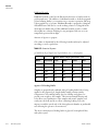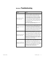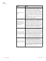
1
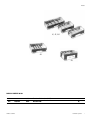
Horizontal Systems
Models A1, A2, A3-1, A5, and M6
Operating and Maintenance Manual 7007301 Rev. 0
Visit us online to register your warranty
www.thermoscientific.com/warranty
Preface
A1, A2, A3-1
A6
A5
MANUAL NUMBER 7007301
0
--
4/10/12
REV
ECR/ECN
DATE
Thermo Scientific
Transfer to Marietta (was 3/2005)
ccs
DESCRIPTION
By
Horizontal Systems
i
Preface
Important Read this instruction manual. Failure to read, understand and follow the instructions in this manual
may result in damage to the unit, injury to operating personnel, and poor equipment performance. s
Caution All internal adjustments and maintenance must be performed by qualified service personnel. s
Warning To avoid the risk of personal shock, always disconnect the gel box from the power supply. Further, the
power supply must be equipped with a shutdown-on-disconnect circuit. Do not move the unit unless the power
source to the unit has been disconnected. s
Statement of Proper Use: Use this product only for its intended purpose as described in this manual. Do not use
this product if the power leads are damaged or if any of its surfaces are cracked.
Running conditions for this unit should not exceed the name plate readings found on the lower buffer chamber.
This Owl System is designed to meet IEC 1010-1 safety standards (IEC 1010-1 is an internationally accepted
electrical safety standard for laboratory instruments).
Material in this manual is for information purposes only. The contents and the product it describes are subject to
change without notice. Thermo Fisher Scientific makes no representations or warranties with respect to this
manual. In no event shall Thermo be held liable for any damages, direct or incidental, arising out of or related to
the use of this manual.
©2012 Thermo Fisher Scientific. All rights reserved.
ii
Horizontal Systems
Thermo Scientific
Preface
Important operating and/or maintenance instructions. Read the accompanying text carefully.
Potential electrical hazards. Only qualified persons should perform procedures associated with this
symbol.
Equipment being maintained or serviced must be turned off and locked off to prevent possible injury.
Hot surface(s) present which may cause burns to unprotected skin, or to materials which may be
damaged by elevated temperatures.
Marking of electrical and electronic equipment, which applies to electrical and electronic equipment
falling under the Directive 2002/96/EC (WEEE) and the equipment that has been put on the market
after 13 August 2005.
This product is required to comply with the European Union’s Waste Electrical & Electronic
Equipment (WEEE) Directive 2002/96/EC. It is marked with the WEEE symbol. Thermo Fisher
Scientific has contracted with one or more recycling/disposal companies in each EU Member State
European Country, and this product should be disposed of or recycled through them. Further
information on Thermo’s compliance with this directive, the recyclers in your country and
information on Thermo products will be available at www.thermofisher.com.
4
Always use the proper protective equipment (clothing, gloves, goggles, etc.)
4 Always dissipate extreme cold or heat and wear protective clothing.
4 Always follow good hygiene practices.
4 Each individual is responsible for his or her own safety.
Thermo Scientific
Horizontal Systems
iii
Preface
Do You Need Information or Assistance on
Thermo Scientific Products?
If you do, please contact us 8:00 a.m. to 6:00 p.m. (Eastern Time) at:
1-740-373-4763
1-800-438-4851
1-877-213-8051
http://www.thermoscientific.com
[email protected]
www.unitylabservices.com
Direct
Toll Free, U.S. and Canada
FAX
Internet Worldwide Web Home Page
Tech Support Email Address
Certified Service Web Page
Our Sales Support staff can provide information on pricing and give you quotations. We can
take your order and provide delivery information on major equipment items or make
arrangements to have your local sales representative contact you. Our products are listed on the
Internet and we can be contacted through our Internet home page.
Our Service Support staff can supply technical information about proper setup, operation or
troubleshooting of your equipment. We can fill your needs for spare or replacement parts or
provide you with on-site service. We can also provide you with a quotation on our Extended
Warranty for your Thermo Scientific products.
Whatever Thermo Scientific products you need or use, we will be happy to discuss your
applications. If you are experiencing technical problems, working together, we will help you
locate the problem and, chances are, correct it yourself...over the telephone without a service
call.
When more extensive service is necessary, we will assist you with direct factory trained
technicians or a qualified service organization for on-the-spot repair. If your service need is
covered by the warranty, we will arrange for the unit to be repaired at our expense and to your
satisfaction.
Regardless of your needs, our professional telephone technicians are available to assist you
Monday through Friday from 8:00 a.m. to 6:00 p.m. Eastern Time. Please contact us by
telephone or fax. If you wish to write, our mailing address is:
Thermo Fisher Scientific
401 Millcreek Road, Box 649
Marietta, OH 45750
International customers, please contact your local Thermo Scientific distributor.
iv
Horizontal Systems
Thermo Scientific
Table of Contents
Thermo Scientific
Section 1
General Information . . . . . . . . . . . . . . . . . . . . . . . . . . . . . . . . . . . . . . . . . .1-1
Unpack and Check Your Order . . . . . . . . . . . . . . . . . . . . . . . . . . . . .1-2
Section 2
Setting Up . . . . . . . . . . . . . . . . . . . . . . . . . . . . . . . . . . . . . . . . . . . . . . . . . . .2-1
Section 3
Using the System . . . . . . . . . . . . . . . . . . . . . . . . . . . . . . . . . . . . . . . . . . . . .3-1
Model A5 Self- Recirculation System . . . . . . . . . . . . . . . . . . . . . . . . .3-2
Section 4
Finishing Up . . . . . . . . . . . . . . . . . . . . . . . . . . . . . . . . . . . . . . . . . . . . . . . . .4-1
Section 5
Technical Tips . . . . . . . . . . . . . . . . . . . . . . . . . . . . . . . . . . . . . . . . . . . . . . .5-1
Section 6
Troubleshooting . . . . . . . . . . . . . . . . . . . . . . . . . . . . . . . . . . . . . . . . . . . . . .6-1
Section 7
Care and Cleaning . . . . . . . . . . . . . . . . . . . . . . . . . . . . . . . . . . . . . . . . . . . .7-1
Section 8
Optional Equipment . . . . . . . . . . . . . . . . . . . . . . . . . . . . . . . . . . . . . . . . . . .8-1
Replacement Parts . . . . . . . . . . . . . . . . . . . . . . . . . . . . . . . . . . . . . . .8-2
Comb Options . . . . . . . . . . . . . . . . . . . . . . . . . . . . . . . . . . . . . . . . . .8-4
Horizontal Systems
v
Section 1
General Information
The Model A1 horizontal large system has the smallest footprint of the
large format device, giving you a space saving device for your extended
runs. This system is ideal for detailed RNA/DNA analysis. The unit runs
from 8 to 96 samples on one gel. A wall comb is available for running
shorter gels and conserving agarose. A programmable power inverter may
be used for field reversal electrophoresis.
The Model A2 horizontal large system is a simple, convenient and fast
system for detailed DNA/RNA analysis on multiple samples. This system
offers the widest variety of comb options and when used with a wall comb
you can cast varying length gels to conserve agarose.
The Model A3-1 horizontal wide system can run from 25 to 600 samples
on one gel. The gel can be cast in varying lengths to help conserve agarose
when fewer samples need to be run utilizing a wall comb. This unit comes
with built in buffer exchange ports to allow for buffer recirculation on
extended runs, if needed. The large number of comb slots gives you sample
and resolving distance flexibility.
The Model A6 horizontal wide system offers a simple, convenient and fast
method for screening multiple samples on a single agarose gel. 25 to 500
samples can be run simultaneously on one gel; producing clear, tight
banding patterns with no “smiling”.
The Model A5 recirculation system offers convenience and versatility. The
A5 recirculation system prevents formation of pH and ionic gradients for
high resolution and uniform reproducible results. The A5 is ideal for long
runs, multiple sample sets or RNA gels. This unit delivers clear results for
samples run over long time periods. It also eliminates uneven migration,
band distortion or disassociation of pH dependent glyoxylated RNA
molecules that can result when ionic depletion occurs. Because the
recirculation system is built right into the buffer chamber, no external
pumps, tubing or stir bars are required.
The models listed above incorporate the end gate gel casting system. The
UVT gel tray incorporates gasketed end gates which provides a leakproof
seal without tape. Built in leveling ensures the casting of flat, uniformly
thick gels. Sample loading is greatly enhanced using micro well pipette
format combs (and a multichannel pipette) engineered specifically for use
with this system. Using these combs and a multichannel pipette, samples
may be loaded directly from a 96-well plate, 8 or 12 at a time. Sample
loading with a multichannel pipette speeds up transfer and reduces chance
of sample order error. Comb slots on the UVT gel tray are positioned so
that you can run multiple sample sets of equal distances simultaneously.
Thermo Scientific
Horizontal Systems
1-1
Section 1
General Information
Unpack and Check
Your Order
Before starting, unpack the unit and inventory your order. If any parts are
missing, contact Technical Services within 7 days of purchase.
SuperSafe™
Lid
Power Supply Lead (2)
End Gate (2)
UVT Gel Tray
Buffer Chamber
Gasket (2)
Leveling Screws (2)
Leveling Base
Combs (3)
Bubble Level
Figure 1-1. A1 and A2 Exploded Parts Diagram
A1 & A2 Parts List
• Buffer Chamber with Three Point Leveling Base
• Combs: (3) 12, 16, and 20 well, 1.5mm Thick
• Super Safe™ Lid with attached Power Supply Leads (2)
• UV Transmissible (UVT) gel tray wth Gasketed End Gates (2)
• Bubble Level
See Section 8 for replacement parts or optional combs.
Specifications and Recommended Running Conditions
1-2
Horizontal Systems
Model
A1
A2
Gel Size (W x L in cm.)
13 x 25
20 x 25
Buffer Capacity
1.6L
2.3L
Time Requirements (hours)
1-4
1-4
Thermo Scientific
Section 1
General Information
Unpack and Check
Your Order (cont.)
Power Supply
Lead (2)
SuperSafe™
Lid
End Gate (2)
Gasket (2)
UVT Gel Tray
Buffer Chamber
Built In Buffer
Exchange Ports
Leveling Screws (2)
Comb (4)
Leveling Base
Bubble Level
Figure 1-2. A3-1 Exploded Parts Diagram
A3-1 Parts List
• Buffer Chamber with Three Point Leveling Base
• (4) Combs:
• (2) 25 well
• (2) 50 well, 1.5mm Thick
• Super Safe™ Lid with attached Power Supply Leads (2)
• UV Transmissible (UVT) gel tray with Gasketed End Gates (2)
• Built in Buffer Exchange Ports
• Bubble Level
See Section 8 for replacement parts or optional combs.
Model . . . . . . . . . . . . . . . . . . . . . . . . . . . . . . . .A3-1
Gel Size (W x L in cm.) . . . . . . . . . . . . . . . .23 x 40
Buffer Capacity . . . . . . . . . . . . . . . . . . . . . . . . .4.5L
Voltage Requirements (V) . . . . . . . . . . . . . . .20-250
Thermo Scientific
Horizontal Systems
1-3
Section 1
General Information
Unpack and Check
Your Order (cont.)
Power Supply
Lead (2)
SuperSafe™
Lid
UVT Gel Tray
End Gate (2)
Buffer Chamber
Gasket (2)
Leveling Screw (2)
Leveling Base
Comb (4)
Bubble Level
Figure 1-3. A6 Exploded Parts Diagram
A6 Parts List
• Buffer Chamber with Three Point Leveling Base
• (4) Combs
• (2) 25 well
• (2) 50 well, 1.5mm Thick
• Super Safe™ Lid with attached Power Supply Leads (2)
• UV Transmissible (UVT) gel tray wth Gasketed End Gates (2)
• Bubble Level
See Section 8 for replacement parts or optional combs.
Specifications and Recommended Running Conditions
Gel Size (W x L in cm.) . . . . . . . . . . . . . . . .23 x 25
Buffer Capacity . . . . . . . . . . . . . . . . . . . . . . .3000ml
Voltage Requirements (V) . . . . . . . . . . . . . . .20-250
1-4
Horizontal Systems
Thermo Scientific
Section 1
General Information
Unpack and Check
Your Order (cont.)
Power Supply
Lead (2)
SuperSafe™
Lid
End Gate (2)
UVT Gel Tray
Buffer Chamber
Gasket (2)
Leveling Screw (2)
Comb (3)
Leveling Base
Conduit Tube
Bubble Level
Figure 1-4. A5 Exploded Parts Diagram
A5 Parts List
• Buffer Chamber with Three Point Leveling Base
• (3) Combs 16, 24, & 36 well, 1.5mm Thick
• Super Safe™ Lid with attached Power Supply Leads (2)
• UV Transmissible (UVT) gel tray wth Gasketed End Gates (2)
• Bubble Level
See Section 8 for replacement parts or optional combs.
Model A5
Gel Size (W x L in cm.) . . . . . . . . . . . . . . . .20 x 25
Buffer Capacity . . . . . . . . . . . . . . . . . . . . . . . . .2.0L
Voltage Requirements (V) . . . . . . . . . . . . . . .20-250
Thermo Scientific
Horizontal Systems
1-5
Section 2
Setting Up
1. Remove the SuperSafe™ lid from the buffer chamber. The SuperSafe™
lid is attached to the back of the unit at the junction of the lids
attached power supply leads to the banana plugs located on the unit.
To remove, hold the front of the buffer chamber with one hand and
pull the lid off; sliding off evenly by holding the center of the back of
the lid.
2. For shipping and convenient storage, the UVT gel tray is packaged
inside the unit with the gasketed end gates in position upon arrival.
Lift the UVT gel tray out of the buffer
chamber.
3. To cast gels, place the UVT gel tray into
the chamber making sure the gel tray rests
level and centered on the platform. Slide
the gasketed end gates into the outermost
grooves on either side of the gel tray. The
end gates should be inserted tightly into
Figure 2-1. End Gates
the grooves with the gasket side facing out.
4. Leveling the unit - Larger size gels make the need to cast and run a
level gel is very important for consistent reproducible results. Level the
unit using the thumbscrews on each side of the front of the unit by
slowly turning one thumbscrew at a time and lining up the bubble in
the level with the center circle (the rear screw is for stability only).
5. Preparing the gel - Using electrophoresis
grade agarose and compatible
electrophoresis buffer, the gel may be
prepared in various ways. The percentage
of agarose and the electrophoretic buffer
used is determined by the size of the
samples to be separated and further
recovery of the samples (see Table 5-1.
Figure 2-2. Pour
The agarose and buffer are mixed and
heated over a heat source, in a microwave oven, or in an autoclave
until the agarose is completely dissolved. The prepared gel then must
be cooled to below 60°C before casting to avoid warping the UVT gel
tray, due to excessive heat. If numerous gels are to be run in one day, a
large volume of gel may be prepared and placed in a covered bottle
stored between 40-60°C in a water bath. This provides a ready gel
supply in a warm liquid form that will solidify quickly when gels are
cast. For further tips on sample preparation and visualization, see Table
5-1.
Thermo Scientific
Horizontal Systems
2-1
Section 2
Setting Up
6. Pour or pipette the correct amount (see
Table 5-2) of warm agarose (<60°C) onto
the UVT gel tray that has been placed into
position in the gel box. Immediately after
pouring, insert the desired comb or combs
into the comb slots to form the sample
wells. If only a small portion of gel is
required for proper sample separation,
multiple combs may be used to run 2, 3, Figure 2-3. End Gates
4, 5 or 10 sets (depending on model) of
equal distance samples simultaneously expanding the number of
samples per gel that may be run. To conserve agarose, a wall comb may
also be used to divide and use a smaller portion of the length of the gel
tray. If a wall comb is used, pipette a bead of agarose along the bottom
and side edges of the wall comb once it has been placed in the tray to
seal the combs edges to the trays bottom and sides. Once this bead is
solidified, the cooled gel may be poured as described. Alternately,
regular tape cut slightly longer then the comb can be placed flat along
the combs surface and the comb angled into place in the gel tray. Extra
tape is then placed on the outside of the comb in the excess tray area
to reinforce the corners. Allow the gel to solidify completely.
Migration Distance
•
Run one sample set on a gel
in each tray.
•
Run two sample sets on a gel
of equal length (comb slots) in
each tray.
•
Run three sample sets on a gel
of equal length samples (comb
slots) in each tray.
Run Length 1X
Run Length 2X
•
2-2
Horizontal Systems
Run Length 3X
Run four sample sets on a gel
Run Length 4X
of equal length samples (comb
slots) in each tray and so on Figure 2-4. Migration Distance
up to 12 rows.
Thermo Scientific
Section 2
Setting Up
Migration Distance (continued)
The following charts show the specific tray options for each model.
One comb for a 23.2 run length
Two combs for two 11.4cm run lengths
Three combs for three 7.5cm run lengths
Four combs for four 5.5cm run lengths
Figure 2-5. A1, A2 and A5 Migration Distance
Thermo Scientific
Horizontal Systems
2-3
Section 2
Setting Up
One comb for a 39.4cm run length
Two combs for two 19.5cm run lengths
Three combs for three 12.9cm run lengths
Four combs for four 9.6cm run lengths
Six combs for six 6.3 run lengths
12 combs for twelve 3cm run lengths
Figure 2-6. A3-1 Migration Distance
One comb for a 23.2cm run length
Two combs for two 11.4cm run lengths
Three combs for three 7.5cm run lengths
Four combs for four 5.5cm run lengths
Five combs for five 4.4 run lengths
Ten combs for ten 2cm run lengths
Figure 2-7. A6 Migration Distance
2-4
Horizontal Systems
Thermo Scientific
Section 3
Using the System
1. Place the gel tray in the buffer chamber, lift the end gates out of the gel
tray. This running position exposes the open ends of the agarose to the
buffer.
2. Pour enough compatible running buffer into the unit to fill both
buffer chambers and completely cover and submerge the gel. Correct
buffer level is clearly marked on the units side wall as “FILL LINE”.
See Recommended Running Conditions (Section 1) for approximate
buffer volumes needed for your unit. Too little buffer may cause the gel
to dry out during the run, while excess buffer may decrease DNA
mobility and cause band distortion.
3. Carefully remove the comb (or combs) by tapping lightly to loosen,
and slowly lifting straight up out of the gel tray to avoid damage to the
wells.
4. Load prepared samples into the wells. Samples should be mixed with a
sample loading buffer; giving weight to the samples so that they drop
evenly into the wells and containing tracking dyes to monitor the gel
run. See available comb section for approximate well volumes (Section
8 - Comb Options).
5. Carefully slide the SuperSafe™ lid with attached power supply leads
onto the unit. This will connect the power cords to the banana plug
electrodes and complete the circuit. Plug the other end of the power
supply leads into an appropriate power supply.
6. Turn on power supply. Refer to Table 4-1 for running conditions.
Carefully monitor the gel run to avoid samples running into the path
of another set of samples.
Thermo Scientific
Horizontal Systems
3-1
Section 3
Using the System
Model A5 SelfRecirculation System
The Model A5 Self-Recirculation System has a unique built-in
recirculating system designed to self recirculate buffer. Bubbles are collected
at the cathode end of the unit and shunted through a conduit tube from
the cathode end of the buffer chamber to the anode end of the buffer
chamber. The bubbles displace buffer creating an effective recirculation
within the chamber.
The self recirculating system reduces formation of pH gradients for high
resolution and uniform, reproducible results. The self-contained
recirculation system requires no external pumps, tubing or stir bars. As
shown in the diagram, a trap at the cathode end of the buffer chamber (1)
collects the hydrogen bubbles produced at the electrode during
electrophoresis. The bubbles are then shunted into a conduit tube (2) to
the anode end of the chamber. This flow of bubbles displaces buffer (3) to
create an internal recirculation system. See page 10 and 24 for Owl Self
Recirculating devices.
See Section 8 - Buffer Exchange Port Option, available for A1, A2 and A6
models.
3-2
Horizontal Systems
Thermo Scientific
Section 4
Finishing Up
1. When the gel run is complete and tracking dye has migrated as far
through the gel as desired, or to the end of the gel, turn off the power
supply and slide off the SuperSafe™ lid to disconnect from the power
source. Carefully remove the tray containing the gel (wear gloves if
ethidium bromide is present). The UV Transmissible (UVT) gel tray
makes visualization and photography with a UV light source easy
without the need to remove the gel from the tray.
2. The buffer chamber, SuperSafe™ lid, UVT gel tray and combs should
be rinsed under warm running water after each use. An RNase/DNase
decontaminate may be used.
Caution This electrophoresis system must never be autoclaved, baked, or
microwaved! s
Table 4-1. Specifications and Recommended Running Conditions
Thermo Scientific
Model
A1
A2
A3-1
A5
A6
Gel Size (W x L in)
13 x 25
20 x 25
23 x 40
20 x 25
23 x 25
Buffer Capacity
1.6L
2.3L
4.5L
2.0L
3000ml
Voltage Requirements (V)
20-250
20-250
20-250
20-250
20-250
Time Requirements (hours)
1-4
1-4
1-6
1-6
1-4
Horizontal Systems
4-1
Section 5
Technical Tips
Running a Standard Ladder
It is recommended to always run a sample lane of
a known “standard ladder” or “marker” to
determine concentration and size of separated
fragments after the gel run, and to aid in
photodocumentation and analysis. Migration
patterns and fragment sizes for commonly used
DNA molecular weight markers are shown in this
figure.
- 23,130
- 9,416
- 6,557
- 4,361
- 2,322
- 2,027
Figure 5-1. Sample Lane
Loading Samples
It is sometimes easier to load the sample wells dry before placing buffer
into the buffer chamber. After the gel solidifies, if cast within the buffer
chamber, remove the gel tray from the buffer chamber and place the tray
on the lab bench. Carefully remove the sample combs by tapping and
lifting straight up. Samples mixed with loading buffer that does not
contain dye may be easier to load dry, especially in larger gel units to avoid
cross contamination. After loading all sample lanes, place the gel tray into
the buffer chamber in the running position with the gel edges facing out
toward the buffer chambers with the gasketed end gates removed and
slowly fill the chamber with buffer.
Thermo Scientific
Horizontal Systems
5-1
Section 5
Technical Tips
Comb Options
Standard
1.0mm and 1.5mm thickness: for all
models. Combs are hand fabricated
for high quality precision in low
volumes. Each comb has an acrylic
spine with Lexan® teeth.
Standard
Preparative
Preparative combs are manufactured
with an acrylic spine and Lexan®
teeth. Used for extremely large
samples.
Preparative
Multi Load Comb
Multi-Load Comb
Figure 5-2. Comb Options
For use with 8-12 channel pipettes.
These unique combs are designed to
allow accurate easy loading from a 96 well plate.
Custom Combs
Calll Technical Services for more information.
Wall Comb
The wall comb is used in your
existing U.V. Transmissible (UVT)
gel tray to allow the ability to cast
smaller gels using the existing gel
Wall Comb
tray and the comb slots. There are
various ways to use the wall comb
Figure 5-3. Wall Comb Option
to ensure a leak proof seal. The
following two are the fastest and easiest.
5-2
Horizontal Systems
Thermo Scientific
Section 5
Technical Tips
Wall Comb (continued)
Tape Method
Using casting tape, transparent tape, or masking tape, cut a piece long
enough to cover the full length of the wall comb with about 1/2"
overhang at each end. Half the width of the tape should be free. Firmly
press the tape all along the comb leaving the three open edges loose.
Place the comb with tape into the gel tray at the desired comb slot
position. The taped side of the comb should be facing away from
where the gel will be cast. Angle the comb as it is being placed into the
comb slot so the loose taped edge is free. Once positioned into the gel
tray, firmly press the tape to the bottom and sides of the gel tray to
form a leakproof seal. Small extra pieces of tape may be added to the
corners afterwards to reinforce the edges. Add cooled (<60°), slightly
thickened agarose to the gel tray and allow to solidify completely. To
remove comb, gently remove excess tape and loosen tape from the
bottom and sides of the gel tray. Carefully pull comb straight up and
out of the comb slot.
Note The edge of the gel may appear irregular, once submerged in running
buffer, the gel run will be unaffected. s
Agarose Plug Method
Place the wall comb into the desired comb slot. Prepare agarose as
usual and remove about 3ml to a test tube. Allow this aliquot to cool
and thicken enough to make a thin partially solid worm of agarose.
Using a Pasteur pipette or other transfer device, gently place a small
stream of agarose all along the three comb edges at the bottom of the
gel tray and sides to form a leakproof seal. Allow “plug” to solidify
completely checking that all exposed areas are filled in with agarose.
Next, add cooled agarose (<60°) to the gel tray. After the gel is
completely solidified; rock the comb back and forth slightly to loosen
it when removing to avoid damage to the gel. Adding running buffer
to the buffer chamber prior to removing comb(s) may make the comb
removal easier.
Thermo Scientific
Horizontal Systems
5-3
Section 5
Technical Tips
Helpful Tips
•
Cooling the agarose slightly more than usual will help eliminate leaking
because the gel thickens as it solidifies and is less likely to leak. To
avoid visible solids due to uneven cooling, gently swirl the agarose.
Exact temperature of the agarose depends on the type used, but the gel
should be thickened yet still evenly liquid so it is pourable and
consistent.
•
Gels of higher concentrations (>0.5%) are also easier to work with,
especially when using the agarose plug method.
Micro Well Format Combs
Micro well format combs, available
with many Owl horizontal and
sequencing devices, are meant to be
Micro Well Format 1X
used in conjunction with an 8- or 12channel pipette. The pipette is
manufactured to be used with a 96
well (8 wells wide x 12 wells long)
multichannel plate. The key here is the Micro Well Format 2X
constant distance of 9mm between the Figure 5-4. Micro Well Combs
center of each well in the multichannel
plate. The multichannel pipette is set up so that the pipette tips are exactly
9mm apart, and a researcher can take up 8 (or 12) samples simultaneously
from the plate.
To be able to load these samples simultaneously onto a gel, the “center to
center” distance between sample wells in the gel must be exactly 9mm. The
micro well format comb that would give this exact distance would be a 1x
micro well format comb. However, the ability to space wells exactly 9mm
apart is dependent on the total width of the gel and the number of sample
wells that the researcher wants in the gel. There are four options that fit the
use of a 9mm “center to center” pipette tip format. The 9mm spacing
represents a 1x option micro well format. By decreasing the center to
center distance in factors of 9mm, one can fit more samples in a given
amount of space with the ability to use the same micro well format pipette.
The 2x is 9 divided by 2, the 3x is 9 divided by 3 and the 4x is 9 divided
by 4.
5-4
Horizontal Systems
Thermo Scientific
Section 5
Technical Tips
Micro Well Format Combs (continued)
Therefore, it is possible to have a greater number of teeth in a comb and
maintain the use of the multichannel pipette, by having the multichannel
pipette fill every other well rather than every well. This type of
multichannel pipette format comb is called a 2x multichannel pipette
format comb. For example, the 50 tooth comb for the A6 device has
“center to center” distances between teeth of 4.5cm. This means that a
researcher would load lanes 1, 3, 5, 7, 9, 11, 13, and 15 with the first pass
of the pipette and 2, 4, 6, 8, 10, 12, 14 and 16 with the second pass, and
so on until all of the lanes are filled.
When using an 8 (or 12)
channel pipette, the
number of sample wells
that can be filled must be
a multiple of 8 (or 12). A
1st Loading
25 well micro well format
comb would have one
extra sample and a 50
well micro well format
comb would have 2 extra
2nd Loading
samples, which a
researcher could fill with
a single channel pipette,
and is generally used for
standards.
Micro Well Format 1X Micro Well Format 2X
Figure 5-5. Loading Micro Wells
Why Recirculate Buffer?
During electrophoresis, gradual ionic depletion of the running buffer
forms an ionic and pH gradient across the system (acetate and phosphate
buffers are especially prone to ionic depletion). Such gradients can cause
uneven migration and banding patterns or cause pH-dependent
glyoxylated RNA molecules to disassociate. Buffer recirculation ensures
uniform ionic strength throughout the system.
Thermo Scientific
Horizontal Systems
5-5
Section 5
Technical Tips
Why Recirculate Buffer? (continued)
Comparison of buffer pH with and without recirculation during
agarose gel electrophoresis
50ng samples of HindIII digested
DNA were run on duplicate gels, with and without buffer
recirculation. pH measurements were taken at the anode and cathode
ends at various time intervals and plotted against time.
Running condition: 1% agarose gel in 10mM NaH2PO4, pH 7.0,
114V, constant voltage.
Figure 5-6. Comparison
Sample Well / Comb Configuration
Hg = height of gel used
Hw = well height
Hs = height of well used for sample volume
How to determine well sample volume:
There are two volumes to
consider when determining the
sample volume for a horizontal
gel. 1) Gel volume, which is
Width x Length x Gel Height
and uses centimeters and 2)
Sample volume which is Tooth
Width x Comb Thickness x
Apparent Well Height, and uses
millimeters.
Figure 5-7. Determine Volume
5-6
Horizontal Systems
Thermo Scientific
Section 5
Section title
How to determine well sample volume (continued):
Gel height is generally set to a height between 0.25 cm and 1.0 cm.
Therefore, once you choose the height, the volume is the gel dimensions
given in the catalog for each gel box (I.D.) times this height. Once the gel
height (Hg) is chosen, the well volume and then the sample volume can be
calculated. The well height (Hw) is 1.5 mm less then the gel height: Hw =
Gel Height – 1.5 mm. Using the well height, the volume of the well is
calculated: Vw = (Well Height) (Tooth width x comb thickness). The
loading volume is a 0.75 safety factor applied to the well volume: Vs =
(Vw) (.75)
For Owl combs, there are two thicknesses, 1.0mm and 1.5mm. This is the
depth. The width of the well is determined by the number of teeth. For a
given gel box, as the number of teeth increase, the volume of each tooth
decreases.
Reagent Information
There are various types of agarose commerically available that may be used.
Besides standard ultra pure electrophoresis grade agarose, there are also
numerous low melting point products for easy sample recovery, as well as
speciality products formulated for specific uses to separate/recover very
small or very large fragments etc.
To visualize and photograph the samples after the gel run for a permanent
record, the gel may be stained during or following the run with a variety of
stains. The most common stain for DNA is ethidium bromide. Ethidium
bromide may be added directly to the gel and running buffer to quickly
and easily visualize and photograph the separated fragments following the
gel run without the need for additonal staining.
If this is not added, then following the gel run the gel may also be soaked
in a concentrated ethidium bromide solution and rinsed for the same
visualization. The ethidium bromide is added to both the gel (after
heating) and the electrophoresis buffer at a concentration of 0.5μg/ml.
Ethidium bromide is a potential carcinogen. Care in handling the powder
and stock solution must be taken. Always wear gloves when handling the
powder, solutions and all gels that contain any amount of ethidium
bromide.
Thermo Scientific
Horizontal Systems
5-7
Section 5
Technical Tips
Table 5-1. Mobility range of DNA in different percentage agarose gels
Agarose % (w/v)
Approximate range of separated DNA fragments (kb)
0.3
60 to 5
0.5
30 to 1
0.7
12 to 0.8
1.0
10 to 0.5
1.2
7 to 0.3
1.5
4 to 0.2
2.0
3 to 0.1
3.0
<0.1
It should be noted, an increased agarose % gives better separation of small
fragments and also bands very close together that tend to be more difficult
to separate, visualize and photograph. A specialty agarose product
formulated to increase resolution of low molecular mass samples may also
be used.
Example: A good mid range gel percentage would be 0.7%, or 0.7g agarose
in 100mls electrophoresis buffer (TBE or TAE), following heating and
dissolving the agarose, 10μl of ethidium bromide stock solution (5mg/ml)
is added. The gel would be run with compatible electrophoretic running
buffer (1X TBE or 1X TAE) that also contained ethidium bromide 1 liter
of the running buffer would contain 100μl of this 5mg/ml ethidium
bromide stock solution.
Preparation & Properties of TAE and TBE Electrophoresis Buffer Systems:
These buffers are used because they both have a basic pH which gives the
phosphate group of the DNA a net negative charge allowing migration of
the DNA toward the positive anode in the electrophoresis chamber.
TAE - Tris acetate with EDTA (40mM Tris base 40mM acetic acid,1mM EDTA)
50X stock solution, pH ~8.5
1X working solution
242g Tris base
40mM Tris acetate
57.1ml glacial acetic acid
1mM EDTA
18.61g Na2EDTA - 2H2O (MW 372.24)
Distilled H2O to 1 liter final volume
5-8
Horizontal Systems
Thermo Scientific
Section 5
Technical Tips
TBE - Tris borate with EDTA (89mM Tris base, 89mM boric acid, 2mM EDTA)
10X stock solution
1X working solution
108g Tris base
89mM Tris base
55g boric acid
89mM boric acid
7.44g Na2EDTA - 2H2O (MW 372.24)
2mM EDTA
(or 40 ml 0.5 M EDTA, pH 8.0)
Distilled H2O to 1 liter final volume
Do not adjust pH
Buffer
Suggested Uses and Comments
TAE Buffer
Use when DNA is to be recovered
For electrophoresis of large (>20kb) DNA
Applications requiring high resolution
Has low ionic strength and low buffering capacity recirculation may be necessary for long runs (>4hrs.)
TBE
Buffer For electrophoresis of small (<1kb) DNA
Better resolution of small (<1kb) DNA
Decreased DNA mobility
High ionic strength and high buffering capacity no recirculation needed for extended run times
TBE buffer reacts with the agarose making smaller pores and a tighter
matrix. This reduces broadening of the DNA bands for sharper resolution.
Thermo Scientific
Horizontal Systems
5-9
Section 5
Technical Tips
Ethidium Bromide
Ethidium bromide is ideal for the flurometric detection of nucleic acids in
gel electrophoresis. The addition of ethidium bromide to both the prepared
gel and running buffer is a convenient way to monitor separation and keep
a photographic log of gel runs. Ethidium Bromide is prepared as 10mg/ml
in distilled water and used as a stock working solution of 5.0μg/ml in the
electrophoresis buffer and gel. Mix ethidium bromide powder or tablet
thoroughly into solution checking for any precipitate and store at room
temperature protected from light.
Amount of Agarose to prepare:
Gel volume is determined by the following formula and may be adjusted
according to need or preference:
Table 5-2. Amount of Agarose
gel width(cm) X gel length (cm) X gel thickness (cm) = ml of agarose
Agarose Volume in ml per gel thickness in cm.
Model #
Gel size(cm) 0.25cm
0.5cm
0.75cm
1.0cm
A1
13x25
81ml
163ml
244ml
325ml
A2
20x25
125
250
375
500
A3-1
23x40
230
460
690
920
A5
20x25
125
250
375
500
A6
23x25
144
288
432
575
Agarose Gel Loading Buffer
Samples are prepared and combined with gel loading buffer before being
applied to the prepared gel. Sample buffer usually contains similar
components to the running buffer, dyes for visibility, and glycerol to
provide some weight to the samples. This increased sample density and
color allows easy visualization of the samples and ensures samples load
evenly into the wells and do not float out during loading. Dyes also
migrate toward the anode end of the electrophoresis chamber at predictable
rates allowing the gel run to be monitored.
The most commonly used loading buffer is glycerol, bromophenol blue,
and xylene cyanol.
5-10
Horizontal Systems
Thermo Scientific
Section 6
Thermo Scientific
Troubleshooting
Problem
Solution
Agarose leaks into chamber
when casting the gel
Check to see if the gasket is correctly seated in groove and
even all the way around. Remove gasket and reseat by
smoothing out gently with your thumb from one end to the
other. Gasket material may have a tendency to absorb salts
from the running buffer. After each use, rinse the end gates
under warm running water to bring back spongelike consistence of the gasket material. Gaskets may eventually become
brittle with frequent use. Contact Technical Services to purchase replacement gaskets.
Check to make sure gasketed end gates have been placed
with in UVT gel tray with gaskets facing out
Bands seem to be running at
an angle.
Check to be sure that the unit is properly leveled for casting
and running the gel by using the front thumbscrews on the
base. Thumbscrews should be adjusted until the bubble in the
level lines up with the levels center circle. Always center the
gel tray holder on the platform and cool the agarose to below
60°C before pouring to avoid warping the UVT gel tray (s).
Samples seem to be running
unevenly in certain areas.
Check that the platinum electrode wire is intact running flat
and evenly across the outer corners and up the side to the
junction of the banana plug area. This problem could also be
caused by regular casting with very hot agarose gel (>60°C)
which may damage the gel tray over time. Always cool the
melted agarose to below 60°C before casting to avoid warping the UVT gel tray (s). Warping the UVT gel tray will cause
all subsequent gels to be cast unevenly.
Samples do not band sharply
and appear diffuse in the gel.
Gels should be allowed to solidify completely before running.
For standard agarose, this would be about 30 minutes, if low
melting point agarose is used, it may be necessary to completely solidify gels at a cooler temperature in the refrigerator
or cold room. Gels should be submerged in 3-5mm of buffer to
avoid gel dry out, but excess buffer >5mm can cause
decreased DNA mobility and band distortion.
Horizontal Systems
6-1
Section 6
Troubleshooting
Problem
Solution
Bands are not sharp, clear,
and even.
Always follow the proper procedure for preparing the agarose
product according to the manufacturers instructions. When
preparing the agarose be sure all the agarose powder is in
solution before heating. In general, add powdered agarose to
distilled water and swirl to mix. Make sure all the powder is
equally wet to ensure proper melting. Heat in a microwave
oven, boiling water bath, or hot plate with occasional swirling
to melt and mix completely. Cool agarose liquid to below 60°
and cast.
Note: High percentage gels may thicken and solidify rapidly
and should be cast while still a liquid.
Samples are not moving as
expected through the gel,
remaining in the wells, or diffusing into the gel.
Check that a complete power circuit is achieved between the
unit and the power supply. Platinum wire and banana plugs
should be intact. To test, simply fill the unit with running
buffer and attach to the power supply without a gel or gel
tray in the unit. The platinum wires on both sides of the unit
should produce small bubbles as the current passes through.
If a complete circuit does not exist there will be few to no
bubbles. Contact Technical Services to schedule a repair.
Always make sure to allow the gel to solidify completely
before moving the gel tray, unit, or removing the comb. To
avoid damage to the sample wells, gently rock the comb back
When the comb is removed
and forth lightly to loosen, then slowly pull the comb straight
from the gel, some sample
up out of the gel tray. This rocking helps to avoid suction as
wells are ripped and damaged. the comb is removed. Alternatively, once casting is complete,
simply submerging the gel with running buffer will help
loosen the comb. Using a higher percentage of agarose that
forms a tighter gel matrix may remedy this problem as well.
The volume of running buffer used to submerge the gel
should only be between 3-5mm over the gel surface. Gel
should be completely submerged to avoid the gel from drying
The gel seems to run slower
out, which can smear the bands and possibly melt the gel (s)
under the usual running condidue to overheating. If excessive running buffer is added, the
tions.
mobility of the DNA decreases and band distortion may result.
Excess buffer causes heat to build up and buffer condensation
inside the unit may result.
6-2
Horizontal Systems
Thermo Scientific
Section 6
Troubleshooting
Additional Sources for Reference
Maniatis T., E. F. Fritsch and J. Sambrook. Molecular Cloning: A
Laboratory Manual, Cold Spring Harbor Laboratory, Cold Spring Harbor,
NY.
Short Protocols in Molecular Biology, - A Compendium of Methods from
Current Protocols in Molecular Biology, Edited by Fredrick M. Ausubel,
et. al.
Adams, D., and R. Ogden, Electrophoresis in Agarose and Acrylamide
Gels, Methods in Enzymology, Vol. 152 (1987) Academic Press, Inc.
Fotador, U.. Simultaneous Use of Standard and Low-Melting Agarose for
the Separation and Isolation of DNA by Electrophoresis, BioTechniques,
Vol. 10, No. 2, (1991)
Boots, S. Gel Electrophoresis of DNA ; Analytical Chemistry, Vol. 61, No.
8, April 15, 1989
Thermo Scientific
Horizontal Systems
6-3
Section 7
Care and Cleaning
Caution Organic solvents cause acrylic to “craze” or crack. Clean all Owl
acrylic systems with warm water and a mild detergent. Do not use ethanol
or other organic solvents to clean Owl products. Do not autoclave, bake,
or microwave your unit. Temperatures over 50°C can damage to the
acrylic. s
Note If an RNase free electrophoresis system is desired, there are various
methods to rid the system of RNA contamination. For fast and easy
decontamination, use RNase Away®*. Spray, wipe or soak labware with
RNase Away, then wipe or rinse the surface clean; it instantly eliminates
RNase. RNase Away eliminates the old methods that include treatment
with 0.1% Diethyl Pyrocarbonate (DEPC) treated water and soaking in
diluted bleach. DEPC is suspected to be a carcinogen and should be
handled with care. This electrophoresis system should never be autoclaved,
baked, or placed in a microwave. s
To order RNase Away, contact Technical Services:
Part Number
Description
7000
250ml bottle
7002
475ml spray bottle
7003
1 liter bottle
7005
4 liter bottle
*Rnase Away® is a registered trademark of Molecular BioProducts
Thermo Scientific
Horizontal Systems
7-1
Section 7
Care and Cleaning
Care of Acrylic
The following chemical compatibility chart is supplied for the convenience
of our customers. Although acrylic is compatible with most solvents and
solutions found in the biochemical laboratory, some solvents can cause
substantial damage. Keep this chart handy to avoid harm to your apparatus
by the use of an inappropriate solvent.
Codes:
S - Safe (no effect, except possibly some staining)
A - Attacked (slight attack by, or absorption of, the liquid)
(slight crazing or swelling, but acrylic has retained most of its strength)
U - Unsatisfactory (softened, swollen, slowly dissolved)
D - Dissolved (in seven days, or less)
This list does not include all possible chemical incompatibilities and safe
compounds. Acrylic products should be cleaned with warm water, a mild
detergent such as Alconox™, and can also be exposed to a mild bleach
solution (10:1). In addition, RNAse removal products are also safe for
acrylic.
7-2
Horizontal Systems
Thermo Scientific
Section 7
Care and Cleaning
Table 5-1. Chemical Compatibility for Acrylic-Based Products
Chemical
Code Chemical
Code Chemical
Code
Acetic acid (5%)
S
Ethyl alcohol (50%)
A
Naptha
S
Acetic acid (Glacial)
D
Ethyl alcohol (95%)
U
Nitric acid (10%)
S
Acetic Anhydride
A
Ethylene dichloride
D
Nitric acid (40%)
A
Acetone
D
Ethylene glycol
S
Nitric acid concentrate
U
Ammonia
S
2-Ethylhexyl Sebacate
S
Oleic acid
S
Ammonium Chloride (saturated)
S
Formaldehyde (40%)
S
Olive oil
S
Ammonium Hydroxide (10%)
S
Gasoline, regular, leaded
S
Phenol 5% solution
U
Hydroxide (10%)
S
Glycerine Heptane (commercial grade)
S
Soap solution (Ivory)
S
Ammonium Hydroxide concentrate
S
Hexane
S
Sodium carbonate (2%)
S
Aniline
D
Hydrochloric acid (10%)
S
Sodium carbonate (20%)
S
Benzene
D
Hydrochloric acid concentrate
S
Sodium chloride (10%)
S
Butyl Acetate
D
Hydrochloric acid (40%)
U
Sodium hydroxide (1%)
S
Calcium chloride (saturated)
S
Hydrogen peroxide (3% solution)
S
Sodium hydroxide (10%)
S
Carbon tetrachloride
U
Hydrogen peroxide (28% solution)
U
Sodium hydroxide (60%)
S
Chloroform
D
Isooctane
S
Sodium hydrochlorite (5%)
S
Chromic acid (40%)
U
Isopropyl alcohol (100%)
A
Sulfuric acid (3%)
S
Citric acid (10%)
S
Kerosene (no. 2 fuel oil)
S
Sulfuric acid (30%)
S
Cottonseed oil (edible)
S
Lacquer thinner
D
Sulfuric acid concentrate
U
Detergent Solution (heavy duty)
S
Methyl alcohol (50%)
A
Toluene
D
Diesel oil
S
Methyl alcohol (100%)
U
Trichloroethylene
D
Diethyl ether
U
Methyl Ethyl Ketone
U
Turpentine
S
Dimethyl formamide
U
Methylene chloride
D
Water (distilled)
S
Dioctyl phthalate
A
Mineral oil (white)
S
Xylene
D
Ethyl acetate
D
Thermo Scientific
Horizontal Systems
7-3
Section 8
Optional Equipment
Optional Multi-Load Tray and Combs
Multiple sample loading configured for
use with an 8 or 12 channel pipette is
available by using the multi-load tray
(A2-RL-12 and A2-RL-24) and combs
(A2-RL-18D).
Figure 8-1. Multi-Load Tray
Buffer Exchange Port Option, for Models A1, A2, and A6
The buffer exchange port option is
used to recirculate the buffer during
extended gel runs. Recirculation is
used to prevent buffer depletion of
certain low ionic running buffers,
for extended runs, multiple sample
sets, or for RNA gels. If your unit
has the buffer exchange port option,
it will be fitted with two white
Figure 8-2. Buffer Exchange Port Option
buffer port terminals and will
contain two separate port inserts
packaged in a small plastic bag located inside the unit upon arrival. Ports
are attached to a user supplied pump.
How these work…
The inserts are pushed into the attached ports on the side wall of the unit
with the black O-ring side facing in. The insert will “snap” into place in
the port in the “open” position and is ready to circulate buffer. Appropriate
tubing is then connected to the small outer ringed ends of the ports for
circulation using a separate recirculator or peristaltic pump. To close the
port, which also releases the insert, you simply press the flat metal button
and the insert detaches. The port is now in the “closed” position.
Note Buffer may also be passed through a heat exchanger. s
Thermo Scientific
Horizontal Systems
8-1
Section 8
Optional Equipment
Contact Technical Services to order replacement parts.
A1 Replacement Parts
Item Description
Catalog No.
Complete System
A1
Complete System with Buffer Exchange Ports
A1-BP
Accessories
Catalog No.
Power Supply Leads
PSL-5
UVT Gel Tray with Gasketed End Gates
A1-UVT
Replacement Gaskets (1 pair)
A1-GK
Replacement End Gates (1 pair)
A1-EG
A2 Replacement Parts
Item Description
Catalog No.
Complete System
A2
Complete System with Buffer Exchange Ports
A2-BP
Accessories
Catalog No.
Power Supply Leads
PSL-5
UVT Gel Tray with Gasketed End Gates
A2-UVT
Multi Load UVT Gel Tray with Gasketed End Gates w/24 slots
A2-RL-UVT
Multi Load UVT Gel Tray with 12 Combs (A2-RL-18D)
A2-RL-12
Multi Load UVT Gel Tray with 24 Combs (A2-RL-18D)
A2-RL-24
Replacement Gaskets (1 pair)
A2-GK
Replacement End Gates (1 pair)
A2-EG
A3-1 Replacement Parts
8-2
Horizontal Systems
Item Description
Catalog No.
Complete System
A3-1
Accessories
Catalog No.
Power Supply Leads
PSL-5
UVT Gel Tray with Gasketed End Gates
A3-UVT-1
Replacement Gaskets (1 pair)
A3-GK-1
Replacement End Gates (1 pair)
A3-1-EG
Thermo Scientific
Section 8
Optional Equipment
A6 Replacement Parts
Item Description
Catalog No.
Complete System
A6
Complete System with Buffer Exchange Ports
A6-BP
Accessories
Catalog No.
Power Supply Leads
PSL-5
UVT Gel Tray with Gasketed End Gates
A6-UVT
Replacement Gaskets (1 pair)
A3-GK-1
Replacement End Gates (1 pair)
A3-1-EG
A5 Replacement Parts
Thermo Scientific
Item Description
Catalog No.
Complete System
A5
Accessories
Catalog No.
Power Supply Leads
PSL-5
UVT Gel Tray with Gasketed End Gates
A2-UVT
Multi Load UVT Gel Tray w/24 Comb Slots
A2-RL-UVT
Multi Load UVT Gel Tray w/12 Combs (A2-RL-18D)
A2-RL-12
Multi Load UVT Gel Tray w/24 Combs (A2-RL-18D)
A2-RL-24
Replacement End Gates (1 pair)
A2-EG
Replacement Gaskets (1 pair)
A2-GK
Bubble Level
BBL-1
Horizontal Systems
8-3
Section 8
Optional Equipment
Comb Options – Model A1
Catalog
Number
Comb
Type
Number
of Teeth
Thickness Width of
of Teeth
Teeth
Recommended Loading Volumes1
A1-8C
Standard
8
1.0 mm
13.9 mm
10 ul
36 ul
63 ul
89 ul
A1-8D
Standard
8
1.5
13.9
16
55
95
133
A1-12C
Standard
12
1.0
8.7
7
23
39
55
A1-12D
Standard
12
1.5
8.7
10
34
59
83
A1-16C
Standard
16
1.0
6.1
5
16
27
39
A1-16D
Standard
16
1.5
6.1
7
24
41
58
A1-20C
Standard
20
1.0
4.5
3
12
20
29
A1-20D
Standard
20
1.5
4.5
5
18
30
43
A1-24C
Standard
24
1.0
3.5
3
9
16
22
A1-24D
Standard
24
1.5
3.5
4
14
24
33
A1-MTC3
Micro Well
14 (1X)
1.0
7.2
5
19
32
46
A1-MTD3
Micro Well
14 (1X)
1.5
7.2
8
28
49
69
A1-PREP
Prep
2
1.5
117/5
130/6
455/20 775/34
A1-WALL
Wall
1
1.5
130
XCM
Custom
0.25cm2 0.5cm2 0.75cm2 1.0cm2
1100/48
1.0, 1.5, 2.0,
3.0
1
Loading Volume is calculated as 75% of total well volume (see page 11)
Gel Thickness
3
8 & 12 Channel Pipette Format
2
8-4
Horizontal Systems
Thermo Scientific
Section 8
Optional Equipment
Comb Options – Model A3-1 & Model A6
Recommended Loading Volumes1
Catalog
Number
Number Thickness Width
Comb Type
of Teeth of Teeth
of Teeth
D3-MTC3
Micro Well
25 (1X)
1.0 mm
7.5 mm
6 ul
20 ul
34 ul
48 ul
D3-MTD3
Micro Well
25 (1X)
1.5
7.5
8
30
51
72
D3-MT2C3
Micro Well
50 (2X)
1.0
3
2
8
14
19
D3-MT2D3
Micro Well
50 (2X)
1.5
3
3
12
20
29
D3-WALL
Wall
1
1.5
230
XCM
Custom
0.25cm2 0.5cm2 0.75cm2 1.0cm2
1.0, 1.5,
2.0, 3.0
1
Loading Volume is calculated as 75% of total well volume (see page 11)
Gel Thickness
3
8 & 12 Channel Pipette Format
2
Thermo Scientific
Horizontal Systems
8-5
Section 8
Optional Equipment
Comb Options – Model A2 and A5
Catalog
Number
Comb
Type
Number
of Teeth
Thickness Width of
of Teeth
Teeth
Recommended Loading Volumes1
A2-8C
Standard
8
1.0 mm
22.7 mm
17 ul
60 ul
102 ul
145 ul
A2-8D
Standard
8
1.5
22.7
A2-12C
Standard
12
1.0
14.5
A2-12D
Standard
12
1.5
14.5
A2-16C
Standard
16
1.0
10.5
A2-16D
Standard
16
1.5
10.5
A2-20C
Standard
20
1.0
8.0
A2-20D
Standard
20
1.5
8.0
A2-24C
Standard
24
1.0
6.5
A2-24D
Standard
24
1.5
6.5
A2-28C
Standard
28
1.0
5.0
A2-28D
Standard
28
1.5
5.0
A2-32C
Standard
32
1.0
4.0
A2-32D
Standard
32
1.5
4.0
A2-36C
Standard
36
1.0
3.5
A2-36D
Standard
36
1.5
3.5
A2-MTC3
Micro Well
14 (1X)
1.0
7.2
5
19
32
46
A2-MTD3
Micro Well
14 (1X)
1.5
7.2
8
28
49
69
A2-MT2C3
Micro Well
A2-MT2D3
Micro Well
130/6
455/20 775/34
0.25cm2 0.5cm2 0.75cm2 1.0cm2
A2-RL-18D3 Micro Well
A2-PREP
Prep
2
1.5
117/5
A2-WALL
Wall
1
1.5
130
XCM
Custom
1100/48
1.0, 1.5, 2.0,
3.0
1
Loading Volume is calculated as 75% of total well volume (see page 11)
Gel Thickness
3
8 & 12 Channel Pipette Format
2
8-6
Horizontal Systems
Thermo Scientific
Thermo Scientific
Rev. 0 9/12
REGISTERED
ISO
9001
If equipment service is required, please call your Technical Services Department at 1-800-438-4851 (USA and Canada) or
1-740-373-4763. We’re ready to answer your questions on equipment warranty, operation, maintenance, service, and special applications. Outside the USA, contract your local distributor for warranty information.
Your local Thermo Sales Office is ready to help with comprehensive site preparation information before your equipment
arrives. Printed instruction manuals carefully detail equipment installation, operation and preventive maintenance.
THIS WARRANTY IS EXCLUSIVE AND IN LIEU OF ALL OTHER WARRANTIES, WHETHER WRITTEN, ORAL, OR
IMPLIED. NO WARRANTIES OF MERCHANTABILITY OR FITNESS FOR A PARTICULAR PURPOSE SHALL APPLY.
Thermo shall not be liable for any indirect or consequential damages including, without limitation, damages to lost profits or
loss of products.
Replacement or repair of component parts or equipment under this warranty shall not extend the warranty to either the
equipment or to the component part beyond the original warranty period. The Technical Services Department must give
prior approval for return of any component or equipment. At Thermo’s option, all non-conforming parts must be returned to
Thermo postage paid and replacement parts are shipped FOB destination.
During the first thirty-six (36) months, component parts proven to be non-conforming in material or workmanship will be
replaced at Thermo’s expense, including labor. Installation, calibration and certification is not covered by this warranty
agreement. The Technical Services Department must be contacted for warranty determination and direction prior to performance of any repairs. Expendable items, glass, filters and gaskets are excluded from this warranty.
The Warranty Period starts two weeks from the date your equipment is shipped from our facility. This allows shipping time
so the warranty will go into effect at approximately the same time your equipment is delivered. The warranty protection
extends to any subsequent owner.
THERMO FISHER SCIENTIFIC OWL PRODUCTS WARRANTY USA
Section 9
Warranty Information
Horizontal Systems
9-1
9-2
Horizontal Systems
Rev. 0 9/12
REGISTERED
ISO
9001
If equipment service is required, please call your Technical Services Department at 1-800-438-4851 (USA or Canada) or
1-740-373-4763. We’re ready to answer your questions on equipment warranty, operation, maintenance, service, and
special applications. Outside the USA, contract your local distributor for warranty information.
Your local Thermo Sales Office is ready to help with comprehensive site preparation information before your equipment
arrives. Printed instruction manuals carefully detail equipment installation, operation and preventive maintenance.
THIS WARRANTY IS EXCLUSIVE AND IN LIEU OF ALL OTHER WARRANTIES, WHETHER WRITTEN, ORAL, OR
IMPLIED. NO WARRANTIES OF MERCHANTABILITY OR FITNESS FOR A PARTICULAR PURPOSE SHALL APPLY.
Thermo shall not be liable for any indirect or consequential damages including, without limitation, damages to lost profits
or loss of products.
Replacement or repair of component parts or equipment under this warranty shall not extend the warranty to either the
equipment or to the component part beyond the original warranty period. The Technical Services Department must give
prior approval for return of any component or equipment. At Thermo’s option, all non-conforming parts must be returned
to Thermo postage paid and replacement parts are shipped FOB destination.
During the first thirty six (36) months, component parts proven to be non-conforming in material or workmanship will be
replaced at Thermo’s expense, excepting labor. Installation, calibration and certification is not covered by this warranty
agreement. The Technical Services Department must be contacted for warranty determination and direction prior to performance of any repairs. Expendable items, glass, filters and gaskets are excluded from this warranty.
The Warranty Period starts two months from the date your equipment is shipped from our facility. This allows shipping
time so the warranty will go into effect at approximately the same time your equipment is delivered. The warranty protection extends to any subsequent owner.
THERMO FISHER SCIENTIFIC OWL PRODUCTS WARRANTY INTERNATIONAL
Section 9
Warranty Information
Thermo Scientific
Thermo Fisher Scientific
81 Wyman Street
P.O. Box 9046
Waltham, Massachusetts 02454-9046
United States
www.thermofisher.com