1
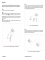
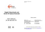
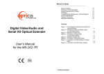
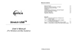
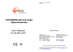
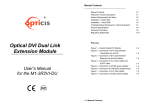
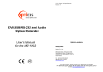
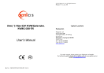
z Manual Contents __________________________________________ www.opticis.com Manual Contents Welcome, Product Description System Requirements for Setup Installation RS-232 Baud rate and AUTO Installation Troubleshooting, Maintenance, Technical Support Product Specifications Warranty Information 1-0 1-1 1-2 1-3 1-6 1-7 1-8 1-9 Pictorials Optical VGA/Audio/RS-232 Extender Figure 1 – Overall Digital Video/Audio and Serial I/O Optical Extender Figure 2 – Connection of VGA, AUDIO, RS232 Cable to Transmitter Module Figure 3 – Connection of Receiver Module Figure 4 – Connection of Two (2) Duplex LC Optical Fibers Figure 5 – Connection of AC/DC Power Adaptor User’s Manual AVFX-100TR 1- 0 Manual Contents 1-1 1-2 1-3 1-4 1-5 Welcome! Congratulations on your purchase of the AVFX-100-TR, Analog Video/Audio and Serial I/O optical extender. This manual contains information that will assist you in installing and operating the product. System Requirements for Setup Hardware requirements You have a graphic controller card with a DVI port in your Windows/Mac (Mac is option), or SUN system. It should support Product Description the maximum graphic resolution feature of the display to be AVFX-100-TR offers integrated extension of Analog video, audio and RS-232 interface up to 2km (6,560feet) over single-mode or 300m (985feet, 50m) over multi-mode. It maintains video signals up to UXGA (1600x1200) at 60Hz refresh rate for PC. It is compatible with full DDC2B. RS232 serial interface offers device-to-device and device-to-controller connections to build up control system for A/V integration. connected. In case of using a computer, no special memory size, CPU speed and chipsets are required. Proper initial trial of the entire platform with its application using a short length copper cable is recommended prior to install with It is designed to multiplex and de-multiplex Analog video, analog audio DDC command interface, HDCP and serial protocol so as to be linked over 4 LC fibers. It gives benefits of all-glass fiber transmission medium, data security, long distance extension up to 2km, easy plug-and-go installation and no RFI/EMI effects. In addition, a non-trivial feature is that both of Single and Multimode optical fibers are applicable. the optical link. Software requirements Shipping Group of AVFX-100-TR Analog Video/Audio and RS232 optical extender Tx and Rx boxes: One Transmitter module & One Receiver module. AC/DC power adapter: Two (2) +5V/3A units User’s Manual Option: Duplex LC Patch Cord (single mode or multi-mode glass fiber). No special needs, if the DVI graphic controller and display peripheral are operational with the platform’s OS and application. AC/DC Power Adapter Technical Advisory The power of AVFX-100-TR is designed to supply to each module of Transmitter and Receiver modules by plugging to each of the power plugs. Figure 1 – Overall Digital Video/Audio and Serial I/O Optical Extender 1-1 Welcome, Product Description 1-2 System Requirements for Setup Installation Important: Please use the installation procedure below. Improper or no operation may result if the start-up sequence is not correctly followed. Step 1 Carefully unpack the contents of the shipping group. Step 4 In the same way as above, connect the Receiver module to the display by VGA copper cable and to the audio output equipments such as media receiver or speaker by audio cable. The RS232 devices near the display can be connected by RS232 copper cable also. Step 2 With system power turned off, connect the Transmitter module to the VGA Dsub of PC or other video source equipment by a VGA copper cable. If necessary, connect the RS232 cable plugs to each D-sub 9-pin connector on PC and Transmitter module. Also if you use a Local monitor, connect HD-15 VGA connector. Step 3 Connect the Transmitter module to the audio source equipment by audio cables such as Stereo Phone Jack. Figure 3 – Connection of Receiver Module Step 5 Remove dust covers and connect two (2) duplex LC fibers to LC receptacles of the Transmitter and Receiver modules, as shown in Fig. 4. Carefully ensure the duplex LC connector is fully engaged. Figure 2 – Connection of VGA, AUDIO, RS232 Cable to Transmitter Module Figure 4 – Connection of Two (2) Duplex LC Optical Fibers 1-3 Installation 1-4 Installation (continued) Notice: Please DO NOT look directly into the LC receptacles of Uplink module, while they are powered on, although they are regulated strictly enough to operate under the Laser Class 1, classified by CDRH/FDA for eye safety. Step 6 Connect an AC/DC power adapter to both Transmitter and Receiver modules as your availability of AC outlets. You can find power indication LED lit on in the both modules. RS-232 Baud rate and AUTO Installation The Tx,Rx Baud rate is installed with switch 1,2,3.(switch 4 is only Auto function) 1 2 3 4 Setting “0” Setting “1” [Baud rate switch diagram] - Black is the switch’s position Switch setting Figure 5 – Connection of AC/DC Power Adapter Step 7 PowerpON the PC and display or connected RS-232 devices. Ensure “POWER”, “VIDEO” and “AUDIO” indication LED lit ON, representing secure connection of LC duplex fibers and all kinds of cables. If the cables are connected incorrectly, the LINK ERR LED lit on. Tip 1: If any status LED is not ON normally after all installation as guided in the above, we recommend you to push “RESET” button while all connections are set and the Transmitter and Receiver modules are powered in. Tip 2: Avoid “hot plugging” the Uplink as this is not recommended practice with live digital voltages. Baud rate 1 2 3 4 9600 0 0 0 0 14400 1 0 0 0 19200 0 1 0 0 38400 1 1 0 0 57600 0 0 1 0 115200 1 0 1 0 128000 0 1 1 0 256000 1 1 1 0 AUTO mode none none none 1 *Auto mode: If you want to use this function, please set the switch as above, and then push the “AUTO” button on the Tx. It can help refine display quality. We recommend you push the button when you finish the set up. 1-6 RS-232 Baud rate and AUTO Installation 1-5 Installation Troubleshooting Product Specifications The display displays only black screen. Check that all AC and DC plugs and jacks used by external power supplies (both Opticis and others) are firmly connected. Ensure that power LED lit ON. Ensure that the Transmitter and Receiver modules connected correctly to the PC and display, respectively. Check if the PC and display are powered on and properly booted. Reset the AVFX-100-TR using Reset button on Uplink and Downlink modules. AVFX-100-TR Analog Video/Audio and Serial I/O Optical Extender Re-boot up the system after reconnecting the LC optical fibers. Screen is distorted or displays noises. Check if the graphic resolution is properly set. Go to the display properties and tap the settings. Reset the AVFX-100 using Reset button on Transmitter and Receiver modules. Push “AUTO” button ※ For more details, please see the 1-6 chapter. Compliance with VGA standard: supports using fiber-optic communication links and DDC2B. Extension limit: 2km (6,560feet) over two (2) single-mode fibers 300m (986feet) over two (2) single-mode fibers Audio: Stereo Phone Jack RS232C: supports D-sub 9 Pin connectors for RS232C. Fiber-optic Connection: The transmitter and receiver boxes of AVFX-100-TR have two (2) duplex LC receptacles connected to two (2) duplex Single Mode or Multi Mode optical patch cords. Mechanical specifications of Transmitter and Receiver boxes Reset the system. Power down, disconnect and reconnect the LC optical fiber or DC power adaptors, and power up. Maintenance No special maintenance is required for this product. Ensure that this product is stored or used in a benign environment free from liquid or dirt contamination. Dimensions: 220mm / 140mm / 40mm (W/H/D) Weight: 460 10.0 gram for each of Transmitter and Receiver. Environmental Specifications Operating temperature: 0°C to 50°C Storage temperature: - 10°C to 85°C Humidity: 5% to 85% AC/DC Power Adapter Power Output: +5V, 3.0 A SMPS DC-power Adapter Cord DC Jack: Core is 5 V and outer cylinder is GND. Support Resolution There are no user serviceable parts. Refer all service and repair issues to Opticis or its authorized distributor. Technical Support and Service For commercial or general product support, contact your reseller. For technical service, contact Opticis by email [email protected] or visit its website at www.opticis.com. 1-7 Troubleshooting, Maintenance, Technical Support Pixel Format Refresh Rate Pixel Format Refresh Rate 800x600 56.0 1280x768 85.0 800x600 60.0 1280x800 60.0 800x600 72.0 1280x960 60.0 800x600 75.0 1280x960 85.0 800x600 85.0 1280x1024 60.0 1024x768 60.0 1280x1024 75.0 1024x768 70.0 1280x1024 85.0 1024x768 75.0 1360x768 60.0 1024x768 85.0 1400x1050 60.0 1152x864 75.0 1400x1050 75.0 1280x768 60.0 1440x900 60.0 1280x768 75.0 1600x1200 60.0 1-8 Product Specifications Warranty Information © 2012 Opticis. All Rights Reserved Revision 1.0 1 (One) Year Warranty Opticis warrants this Digital Video/Audio and Serial I/O Optical Extender to be free from defects in workmanship and materials, under normal use and service, for a period of one (1) year from the date of purchase from Opticis or its authorized resellers. If a product does not work as warranted during the applicable warranty period, Opticis shall, at its option and expense, repair the defective product or part, deliver to customer an equivalent product or part to replace the defective item, or refund to customer the purchase price paid for the defective product. All products that are replaced will become the property of Opticis. Replacement products may be new or reconditioned. Any replaced or repaired product or part has a ninety (90) day warranty or the reminder of the initial warranty period, whichever is longer. Opticis shall not be responsible for any software, firmware, information, or memory data of customer contained in, stored on, or integrated with any products returned to Opticis for repair under warranty or not. Warranty Limitation and Exclusion Opticis shall have no further obligation under the foregoing limited warranty if the product has been damaged due to abuse, misuse, neglect, accident, unusual physical or electrical stress, unauthorized modifications, tampering, alterations, or service other than by Opticis or its authorized agents, causes other than from ordinary use or failure to properly use the product in the application for which said product is intended. Dispose of Old Electrical & Electronic Equipment (Applicable in the European Union and other European countries with separate systems) This symbol on the product or on its packaging indicates that this product shall not be treated as household waste. Instead it shall be handed over to the applicable collection point for the recycling of electrical and electronic equipment. By ensuring this product is disposed of correctly, you will help prevent potential negative consequences for the environment and human health, which could otherwise be caused by inappropriate waste handling of this product. The recycling of materials will help to conserve natural resources. For more detailed information about recycling of this product, please contact your local city office, your household waste disposal service or the shop where you purchased the product. 1-9 Warranty Information Opticis Locations Opticis Co., Ltd. #304 Byucksan Technopia 434-6 Sangdaewon-Dong, Chungwon-Ku Sungnam City, Kyungki-Do 462-120, South Korea Tel: +82 (31) 737-8033 Fax: +82 (31) 737-8079 For order support, please contact your Distributor or Reseller. For technical support, check with the Opticis web site www.opticis.com or contact [email protected]