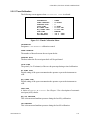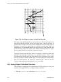
1
Total Reactive Nitrogen Oxides Analyser User Manual Revision: D www.ecotech.com EC9843 Quick Start Guide. Step 1 – Installation: • • • • • • • Inspect analyzer for damage before turning on. Service Manual:- 1.1. Select an appropriate location. Operation Manual:- 2.1.1. Connect Gas lines. Operation Manual:- 2.1.2.2. Connect Analog Output Cables. Operation Manual:- 2.1.2.1. Connect RS232 Cables. Operation Manual:- 4.2.1. Check the mains power selection switch (115 or 230 VAC).Operation Manual:- 2.2. Connect AC Mains Power. Operation Manual:- 2.2. Step 2 – Start-up: • • • • • Set Service Switches. Service Manual:- 1.1.2. Turn On power. Operation Manual:- 2.2. The Display should read “9843 NOy Analyzer”. Adjust the Display Contrast if required. Operation Manual:- 2.2.1. Verify that the software is running by observing the Ecotech Globe rotating in the bottom left hand corner of the display. Step 3. – Operation: • • • • • Verify Instrument warm up and operation mode. Set the correct time and date. If using RS232, configure the Interface menu. Check SYSTEM FAULTS menu. All PASS. Verify other menu settings. Service Manual:- 2.2. Operation Manual:- 2.3.3. Operation Manual:- 2.5.11. Operation Manual:- 2.5.21. Service Manual:- 4.2. Step 4. – Calibration: • • • • • • Perform a quick (single point) calibration. Setup and Calibrate the Analog Outputs (if applicable). If necessary, perform a leak check. If necessary, perform a pressure calibration. If necessary, perform a converter efficiency check. If necessary, perform a Multipoint calibration. Operation Manual:- 2.4. Operation Manual:- 2.6.3. Service Manual:- 3.3.11. Service Manual:- 3.5. Operation Manual:-3.5.4. Operation Manual:- 3.5. Step 5. – Data Validation: • • Verify the results from your data acquisition system agree with the readings of the EC9843 NOy analyzer. Verify that the analyzer responds to automatic calibration sequences. The analyzer is now operating correctly. FRONT MATTER Table of Contents MANUAL HISTORY ................................................................................................................................................ 1-1 NOTICE .................................................................................................................................................................. 1-2 MARK DECLARATION ..................................................................................................................................... 1-3 INTERNATIONALLY RECOGNIZED SYMBOLS USED ON ECOTECH EQUIPMENT ........................................................ 1-4 SAFETY REQUIREMENTS ........................................................................................................................................ 1-5 EQUIPMENT RATING .............................................................................................................................................. 1-5 ENVIRONMENTAL CONDITIONS .............................................................................................................................. 1-5 FACTORY SERVICE................................................................................................................................................. 1-7 CLAIMS FOR DAMAGED SHIPMENTS AND SHIPPING DISCREPANCIES ..................................................................... 1-8 SERVICE AND SPARE PARTS ................................................................................................................................... 1-9 1.0 DESCRIPTION ................................................................................................................................................. 1-1 1.1 SPECIFICATIONS ............................................................................................................................................... 1-2 1.1.1 Range ................................................................................................................................................. 1-2 1.1.2 Noise (RMS)....................................................................................................................................... 1-2 1.1.3 Lower Detectable Limit ..................................................................................................................... 1-2 1.1.4 Zero Drift........................................................................................................................................... 1-2 1.1.5 Span Drift .......................................................................................................................................... 1-2 1.1.6 Lag Time ............................................................................................................................................ 1-3 1.1.7 Rise/Fall Time, 95% of Final Value .................................................................................................. 1-3 1.1.8 Linearity Error .................................................................................................................................. 1-3 1.1.9 Precision............................................................................................................................................ 1-3 1.1.10 Sample Flow Rate ......................................................................................................................... 1-3 1.1.11 Sample Pressure Dependence....................................................................................................... 1-3 1.1.12 Temperature Range....................................................................................................................... 1-3 1.1.13 Power ............................................................................................................................................ 1-3 1.1.14 Weight ........................................................................................................................................... 1-3 1.1.15 Analog Output............................................................................................................................... 1-3 1.1.16 Digital Output ............................................................................................................................... 1-4 2.0 INSTALLATION AND OPERATION............................................................................................................ 2-1 2.1 MECHANICAL INSTALLATION........................................................................................................................... 2-1 2.1.1 Selecting a Location .......................................................................................................................... 2-1 2.1.2 Connections ....................................................................................................................................... 2-1 2.2 AC POWER CONNECTION ................................................................................................................................. 2-7 2.2.1 Display Adjustments .......................................................................................................................... 2-8 2.2.2 Warmup ............................................................................................................................................. 2-9 2.3 OPERATION ...................................................................................................................................................... 2-9 2.3.1 General Operation Information......................................................................................................... 2-9 2.3.2 Using the Menu and Making Entries ............................................................................................... 2-10 2.3.3 Setting the Date and Time................................................................................................................ 2-11 2.4 ANALYZER CALIBRATION .............................................................................................................................. 2-11 2.4.1 Precision Checks ............................................................................................................................. 2-12 2.4.2 Automatic......................................................................................................................................... 2-12 2.4.3 Manual............................................................................................................................................. 2-12 2.4.4 Analyzer Calibration Instructions ................................................................................................... 2-12 2.5 MENUS AND SCREENS .................................................................................................................................... 2-15 Primary Screen..................................................................................................................................... 2-16 2.5.1 ............................................................................................................................................................... 2-16 2.5.2 Main Menu....................................................................................................................................... 2-17 2.5.3 Instrument Menu.............................................................................................................................. 2-17 2.5.4 Measurement Menu ......................................................................................................................... 2-19 98437600 Rev D EC9843 NOy ANALYZER OPERATION MANUAL 2.5.5 Calibration Menu ............................................................................................................................ 2-20 2.5.6 Test Menu ........................................................................................................................................ 2-22 2.5.7 Output Test Menu ............................................................................................................................ 2-24 2.5.8 Preprocessor Pots Menu.................................................................................................................. 2-24 2.5.9 Valve Test Menu .............................................................................................................................. 2-25 2.5.10 Diagnostic Menu......................................................................................................................... 2-26 2.5.11 Calculation factors...................................................................................................................... 2-27 2.5.12 Interface Menu ............................................................................................................................ 2-28 2.5.13 Analog Output Menu................................................................................................................... 2-29 2.5.14 NO/NOy Output Menus ............................................................................................................... 2-29 2.5.15 Data Logging Menu .................................................................................................................... 2-31 2.5.16 Network Adaptor Menu............................................................................................................... 2-32 2.5.17 Trend Select Menu ...................................................................................................................... 2-32 2.5.18 Event Log Screen ........................................................................................................................ 2-33 2.5.19 Instrument Status Screen............................................................................................................. 2-33 2.5.20 System Temperatures Screen ...................................................................................................... 2-34 2.5.21 System Faults Screen .................................................................................................................. 2-35 2.6 ANALOG OUTPUT........................................................................................................................................... 2-36 2.6.1 OFFSET AND LIVE ZERO ........................................................................................................................ 2-36 2.6.2 OVER RANGE ADJUSTMENT .................................................................................................................. 2-37 2.6.3 ANALOG OUTPUT CALIBRATION PROCEDURE ....................................................................................... 2-38 2.6.4 CALIBRATION REQUIREMENTS .............................................................................................................. 2-39 2.7 PASSWORD PROTECTION ................................................................................................................................ 2-40 2.7.1 Rules of Operation........................................................................................................................... 2-40 2.7.2 Sample Session ................................................................................................................................ 2-40 3.0 CALIBRATION ................................................................................................................................................ 3-1 3.1 OVERVIEW ....................................................................................................................................................... 3-1 3.2 ANALYZER CALIBRATION INSTRUCTIONS ........................................................................................................ 3-2 3.3 CALIBRATION AND ZERO/SPAN CHECK SCHEDULE .......................................................................................... 3-4 3.4 CALIBRATION STANDARDS .............................................................................................................................. 3-5 3.4.1 Standard Source of NO...................................................................................................................... 3-5 3.4.2 Preparing the NO Regulator and Delivery System............................................................................ 3-5 3.4.3 Reagents............................................................................................................................................. 3-6 3.5 MULTIPOINT CALIBRATION PROCEDURE: NO CONCENTRATION STANDARD AND GPT ................................... 3-7 3.5.1 Preparation........................................................................................................................................ 3-7 3.5.2 Zero Measurement ............................................................................................................................. 3-8 3.5.3 Span Adjustment ................................................................................................................................ 3-9 3.5.4 Preliminary Converter Efficiency Check ......................................................................................... 3-10 3.5.5 Preparation of the NO and NOy Calibration Curves ...................................................................... 3-11 3.6 GUIDELINES FOR CALIBRATION USING GPT .................................................................................................. 3-12 3.6.1 Principle .......................................................................................................................................... 3-12 3.6.2 Preliminary GPT Design Considerations........................................................................................ 3-12 3.6.3 Major Equipment Required ............................................................................................................. 3-13 3.6.4 System Setup .................................................................................................................................... 3-13 3.6.5 Dynamic Parameter Specifications ................................................................................................. 3-14 3.6.6 Helpful Formulas for Calibration by GPT ...................................................................................... 3-16 3.7 CERTIFICATION OF WORKING STANDARDS AGAINST NIST-TRACEABLE STANDARDS .................................. 3-17 3.8 CALIBRATION REQUIREMENTS WHEN OVER-RANGING IS EMPLOYED ........................................................... 3-19 3.9 AUTOMATIC ZERO/SPAN CHECKS (AZS)....................................................................................................... 3-20 3.9.1 U.S. EPA Definitions ....................................................................................................................... 3-20 3.9.2 AZS Outline...................................................................................................................................... 3-20 3.9.3 AZS Setup......................................................................................................................................... 3-23 3.9.4 Description of the AZS Process ....................................................................................................... 3-24 3.10 CALIBRATION REFERENCES ......................................................................................................................... 3-24 98437600 Rev D FRONT MATTER 4.0 DIGITAL COMMUNICATION ...................................................................................................................... 4-1 4.1 DISCRETE CONTROL ........................................................................................................................................ 4-1 4.1.1 50-Pin I/O Functional Specification.................................................................................................. 4-1 4.1.2 50-Pin I/O Inputs ............................................................................................................................... 4-4 4.1.3 50-Pin I/O Outputs ............................................................................................................................ 4-4 4.2 SERIAL CONTROL............................................................................................................................................. 4-5 4.2.1 Serial Connections............................................................................................................................. 4-5 4.2.2 Cable Connections............................................................................................................................. 4-6 4.3 SERIAL TERMINAL CONTROL ........................................................................................................................... 4-6 4.4 SERIAL COMMAND CONTROL .......................................................................................................................... 4-7 4.4.1 9800 Command Set Format............................................................................................................... 4-7 4.4.2 Bavarian Network Command Set Format.......................................................................................... 4-8 4.4.3 Protocol Definition and Selection.................................................................................................... 4-10 4.4.4 Establishing Communications ......................................................................................................... 4-13 4.4.5 Serial Command Sets....................................................................................................................... 4-16 4.5 USB COMMUNICATION .................................................................................................................................. 4-25 4.5.1 Installing the driver on a PC ........................................................................................................... 4-26 4.6 EC9800 COMMUNICATOR SOFTWARE ........................................................................................................... 4-28 4.6.1 Data Acquire Mode ......................................................................................................................... 4-28 4.6.2 Remote Terminal Mode.................................................................................................................... 4-30 4.6.3 Settings............................................................................................................................................. 4-32 4.6.4 Keyboard shortcuts.......................................................................................................................... 4-33 INDEX .........................................................................................................................................................................II APPENDIX A..............................................................................................................................................................II DESCRIPTION .............................................................................................................................................................II APPENDIX B...........................................................................................................................................................VII 98437600 Rev D EC9843 NOy ANALYZER OPERATION MANUAL This page is intentionally left blank. 98437600 Rev D FRONT MATTER Manual History This manual is the update of a previous version manual: ML9843 Operation Manual, PN: 98430015, Rev. I, January 2003. The scope of this new manual covers the following analyzer: EC9843 Total Reactive Nitrogen Oxides Analyzer, PN: 98433000-100. This instrument is manufactured by Ecotech P/L in Australia and support the new (SMD) Microprocessor Board (Part number 98000063-4). This manual is current for firmware version 1.34 and above. Ecotech Manual ID: Manual PN: Current Revision: Date Released: Description: MAN 0020 98437600 D. May 2008. EC9843 Total Reactive Nitrogen Oxides Analyzer, Operation Manual. Revision History Rev Date Summary Affected Pages A June 2006 New Release for new Microprocessor Board. Based on original manual. All B May 2007 Updated specifications, language, company address and PDF links created. All C October 2007 Updated Specifications 1-2 D May 2008 Various corrections All NOTE: The photograph on the binder of this manual is of the south coast of Australia during Bushfires in 2003. The photograph is courtesy of Earth Sciences and Image Analysis Laboratory, NASA Johnson Space Center. Photo Reference: ISS006-E-19897. 98437600 Rev D EC9843 NOy ANALYZER OPERATION MANUAL Notice The information contained in this manual is subject to change without notice and does not represent a commitment on the part of the Ecotech Pty Ltd. Ecotech reserves the right to make changes in construction, design, specifications, and/or procedures that may not be reflected in this manual. Copyright © 2008. All rights reserved. Reproduction in any form is prohibited without the written consent of Ecotech Pty Ltd. This manual is furnished on the express condition that the information herein will not be used for second source procurement, or purposes directly or indirectly detrimental to the interests of Ecotech. 98437600 Rev D FRONT MATTER MARK DECLARATION Declaration of Conformity Total Reactive Nitrogen Oxides Analyzer Scope of Declaration This declaration applies to Total Reactive Nitrogen Oxides Analyzers as manufactured by Ecotech P/L and which may be sold in the following configurations: Part Number 98433000-100 Description Total Reactive Nitrogen Oxides Analyzer Ecotech certifies that this product operates in compliance with the following standards: EN 61326-1 Electrical Equipment for measurement, control and laboratory use – EMC Requirements Edition 1.1 with amendment 1 plus amendment 2. Immunity Requirements EN61326-1 IEC-61000-4-11 Voltage Interrupts IEC-61000-4-11 Voltage Dips IEC-61000-4-3 Radiated RF electromagnetic field immunity test IEC-61000-4-4 Electrical fast transient/burst immunity test IEC-61000-4-5 Surge immunity test IEC-61000-4-6 Immunity to conducted disturbances, induced by radio frequency fields Electromagnetic compatibility EN61326-1 Annex A CISPR 22 and CISPR 16-2 CISPR 16-1 and CISPR 16-2 EN 61010-1 Safety requirements for electrical equipment, control and laboratory use Section 19 of EN 60204-1 Insulation Resistance Check Residual Voltage Check Earth Continuity The equipment must be operated as per the directions given by Ecotech P/L in this manual. 98437600 Rev D EC9843 NOy ANALYZER OPERATION MANUAL Internationally Recognized Symbols Used on Ecotech Equipment IEC 60417, No. 5016 Electrical fuse IEC 60417, No. 5017 Earth (ground) terminal IEC 60417, No. 5021 Equipotentiality IEC 60417, No. 5032 Alternating current IEC 60417, No. 5041 Caution, hot surface ISO 7000-0434 Caution, refer to accompanying documents ISO 3864, No. B.3.6 Caution, risk of electric shock 98437600 Rev D FRONT MATTER Safety Requirements To reduce risk of personal injury caused by electrical shock, follow all safety notices and warnings in this documentation. This equipment should always be used with a protective earth installed. The EC9843 is compliant with the requirements of EN61010-1 A2:1995, Safety Requirements for Equipment for Measurement, Control, and Laboratory Use. If the equipment is used for purposes not specified by the manufacturer, the protection provided by this equipment may be impaired. Replacement of any part should only be carried out by qualified personnel, only using parts specified by the manufacturer. Always disconnect power source before removing or replacing any components. The Ozone Generator contains dangerous levels of voltage. Make sure the power is disconnected when opening the generator unit. If unfamiliar with the ozone generator refer to figure 8 in the service manual. This unit generates Ozone, for this reason, the exhaust pump must be connected through a charcoal scrubber to remove excess ozone. Surfaces marked with a “Caution, Hot Surface” (see internationally recognized symbols on page 4) sticker may get hot and deliver burns. Measure the temperature on the surface before making any contact with it. Equipment Rating 100-120/220-240V~ ±10% 50/60 Hz 250 VA max FUSE: 5A for 115V operation 3.15A for 240V operation All wiring must be in accordance with local norms and be carried out by experienced personnel. Environmental Conditions RELATIVE HUMIDITY 10% to 80% Temperature 5 to 40 degrees C Pollution degree 2 Installation category II Maximum altitude 2000m. 98437600 Rev D EC9843 NOy ANALYZER OPERATION MANUAL Instruments suitable for use in a sheltered environment only. Never operate this equipment in the presence of flammable liquids or vapors, as this could cause a safety hazard. Warning The converter module must not be opened whilst still hot or powered up UNDER ANY CIRCUMSTANCES. The converter enclosure can contain exposed 110V along with temperatures that can reach in excess of 70°C. The converter encasing should only be opened 30-60 minutes after power has been removed. 98437600 Rev D FRONT MATTER Factory Service We strive to provide efficient and expedient service when an instrument or component is returned for repair. Your assistance can help us to better provide the service you need. To ensure that we process your factory repairs and returned goods efficiently and expeditiously, we need your help. Before you ship any equipment to our factory, please call our Service Response Center at (+61) 1300 364 946. This enables us to complete the necessary paperwork and process your equipment correctly when it reaches our facility. When you call, please be prepared to provide the following information: 1. 2. 3. 4. 5. 6. 7. Your name and telephone number Your company name with shipping address The number of items being returned The part number of each item The model number or a description of each item The serial number of each item, if applicable A description of the problem you are experiencing if factory repair is needed, or the reason you are returning the equipment (e.g., sales return, warranty return, etc) 8. The original sales order number or invoice number related to the equipment 9. Whether repair work is under warranty or is to be billed and a purchase order number for any work to be billed. When you call in, our Customer Service Representative will assign a Return Material Authorization (RMA) number to your shipment and initiate the necessary paperwork to process your equipment as soon as it reaches us. Please include this RMA number when you return equipment, preferably both inside and outside the shipping container. This will ensure that your equipment receives the most prompt attention possible. If the RMA number is not marked on the outside of the shipping container, the shipment will be rejected when it reaches our facility, and returned at your expense. Your assistance in this matter will enable us to serve you better. We appreciate your cooperation and support of our products and services. 98437600 Rev D EC9843 NOy ANALYZER OPERATION MANUAL Claims for Damaged Shipments and Shipping Discrepancies Damaged Shipment 1. Inspect all instruments thoroughly on receipt. Check material in the container(s) against the enclosed packing list. If the contents are damaged and/or the instrument fails to operate properly, notify the carrier and Ecotech immediately. 2. The following documents are necessary to support claims: a. b. c. d. Original freight bill and bill of lading Original invoice or photocopy of original invoice Copy of packing list Photographs of damaged equipment and container You may want to keep a copy of these documents for your records also. Refer to the instrument name, model number, serial number, sales order number, and your purchase order number on all claims. Upon receipt of a claim, we will advise you of the disposition of your equipment for repair or replacement. Shipping Discrepancies Check all containers against the packing list immediately on receipt. If a shortage or other discrepancy is found, notify the carrier and Ecotech immediately. We will not be responsible for shortages against the packing list unless they are reported promptly. 98437600 Rev D FRONT MATTER Service and Spare Parts For world wide customer service & spare parts contact ECOTECH: Address: Ecotech Pty Ltd 1492 Ferntree Gully Rd Knoxfield Australia. VIC 3180 Phone: Fax: +61 1300 264 946 +61 1300 668 763 Email - Service: Email - Spare Parts: [email protected] [email protected] Web: www.ecotech.com.au Our Service Response Center handles product information, application assistance, factory repair, training, service, maintenance agreements, and technical assistance. 98437600 Rev D EC9843 NOy ANALYZER OPERATION MANUAL WARNING Avoid smoking in the vicinity of the analyzer. Due to the complex chemical makeup of tobacco smoke, smoke drawn into the sample line may result in incorrect readings. Furthermore, tobacco smoke has been shown to contaminate converter and scrubber materials critical to the accuracy and stability of the analyzer. 98437600 Rev D CHAPTER 1, DESCRIPTION 1.0 Description The EC9843 Total Reactive Nitrogen analyzer uses gas-phase chemilluminescence detection to perform continuous analysis of Total Reactive Nitrogen Oxides (NOy) and Nitrogen Oxide (NO). The 9843 analyzer design represents an advance in Total Reactive Nitrogen analysis technology achieved by using adaptive microprocessor control of a single measurement channel. The instrument consists of a pneumatic system, a reaction cell, detector (PMT), and processing electronics and must be used in conjunction with the NOy 1000 converter. With an auto-zero routine that allows the analyzer to periodically check and correct for background illumination, the EC9843 virtually eliminates zero drift. In addition to temperature and pressure compensation, the analyzer can adjust the span ratio based on a known concentration of gas used to span the analyzer. This feature is not automatically implemented and must be selected by the operator. Analog and digital outputs are available for data monitoring. The operator can select analog output as either current or voltage output. Current ranges are 0 to 20 mA, 2 to 20 mA, or 4 to 20 mA. Voltage outputs with the 50-pin I/O board include 0 to 10 V, 0 to 5 V, 0 to 1 V, and 0 to 0.1 V. Data collection and recording is available for either a data acquisition system (such as a datalogger) or a strip chart recorder. With the DB50 connector supplied, voltage outputs of 0 to 1v are available well as digital input control and digital output status. The EC9843 also features internal data storage capabilities. The instrument includes an over-range feature that, when enabled, automatically switches the analog output to a preselected higher range if the reading exceeds 90% of the nominal range. When the reading returns to 80% of the nominal range, the analyzer automatically returns to that range. 98437600 Rev D 1-1 EC9843 NOy ANALYZER OPERATION MANUAL 1.1 Specifications Note All specifications are referenced to STP (standard temperature and pressure). 1.1.1 Range Display: Autoranging 0 to 2000 ppb. Resolution = 1 ppt (selectable units and decimal places). Analog output: 0 to full scale from 0-5 ppb to 0-2000 ppb with 0%, 5%, and 10% offset. Autoranging between 2 user-specified full scale values. Zero offset on NOy and NO channels ±10 ppb 1.1.2 Noise (RMS) Measurement process: 25 ppt or 0.1% of concentration reading, whichever is greater; with Kalman filter active. (Measurement process noise available at RS232 port.) Analog output: 0.25 ppb or 0.1% of analog output full scale, whichever is greater. 1.1.3 Lower Detectable Limit Measurement process: Less than 50ppt or 0.5% of concentration reading, whichever is greater; with Kalman filter active. Analog output: 0.5 ppb or 0.2% of analog output full scale, whichever is greater. 1.1.4 Zero Drift Temperature dependent, 0.2 ppb per °C. Time dependent, at fixed temperature: 24 hours: Less than 100 ppt 30 days: Less than 100 ppt. 1.1.5 Span Drift Temperature dependent, 0.1% per °C. Time dependent, at fixed temperature. 24 hours: 1% of reading 30 days: 1% of reading. 1-2 98437600 Rev D CHAPTER 1, DESCRIPTION 1.1.6 Lag Time Less than 120 seconds. 1.1.7 Rise/Fall Time, 95% of Final Value 95% of final value less than 300 seconds with Kalman filter active for concentrations greater than 10 ppb. 1.1.8 Linearity Error ±1 of full scale (from best straight-line fit). 1.1.9 Precision 50ppt or 0.5% of reading, whichever is greater. 1.1.10 Sample Flow Rate 0.73 SLPM (cell flow rate) 1.138 SLPM (total flow rate) 1.1.11 Sample Pressure Dependence A 5% change in pressure produces less than 1% change in reading up to 2000m above sea level. 1.1.12 Temperature Range 5° to 40° C (41° to 104° F). 1.1.13 Power Analyzer: 99 to 132 VAC; 198 to 264 VAC; 47 to 63 Hz. Converter: 110 VAC, 50/60 Hz, 240VAC, 50/60 Hz 1.1.14 Weight Analyzer: 27.7 kg (61 lb) Converter: 11Kg (25lb). 1.1.15 Analog Output 98437600 Rev D Menu selectable current output of 0-20 mA, 2-20 mA, and 4-20 mA. Jumper selectable voltage output of 100 mV, 1 v, 5 V, and 10 V, with menu selectable zero offset of 0%, 5%, or 10%. Independent output for NO, and NOy. 1-3 EC9843 NOy ANALYZER OPERATION MANUAL 1.1.16 Digital Output 1-4 Multidrop RS232 port shared between analyzers for data, status, and control. Service RS232 port gives front panel access to a local or remote user. USB port connection on the rear panel provides data transfer and control. DB50 with discrete status, user control, and analog output. 98437600 Rev D CHAPTER 2, INSTALLATION & OPERATION 2.0 Installation and Operation 2.1 Mechanical Installation Note Before installation, the unit should be checked to ensure that the instrument arrived undamaged. The EC9843 Service Manual contains initial installation inspection instructions. 2.1.1 Selecting a Location Select a location for the analyzer where temperature variation, dust, and moisture are minimal. The location should be well ventilated and should allow convenient access to the operator controls and front panel display. The analyzer can operate in a range of 5° to 40° C without risk of damage. 2.1.1.1 Rack Mount or Enclosed Location The analyzer is supplied as a bench-top version with rubber feet or with the chassis slides to convert it to a rack-mount version. The optional rack-mount version is 24 inches (61 cm) deep and fits into a 19 inch (48.3 cm) RETMA instrumentation rack. The front panel will protrude slightly. Refer to the instructions provided with the rack-mount kit for assembly into a rack. Caution The rack-mount version requires a properly ventilated rack enclosure. The temperature inside enclosures that are not properly ventilated may rise as much as 15° C above the ambient air temperature. This may force the analyzer to operate outside of specifications. Optimum operation is obtained at an operating temperature of 20°C to 30°C inside the rack enclosure. For ventilation calculations, use a heat dissipation rating of 150 watts or 512 Btu per hour. After the analyzer has been mounted, make the pneumatic and electrical connections. 2.1.2 Connections All pneumatic connections must be secure to ensure accurate operation of the analyzer. The following information describes connection techniques for pneumatic and electrical connections. Figure 2-1 shows the rear panel of the analyzer with associated connections. Connection with the NOy-1000 converter 98437600 Rev D 2-1 EC9843 NOy ANALYZER OPERATION MANUAL can be found within the NOy-1000 user manual (MAN 0050). Notice the Network connection is optional RS 232 USB NETWORK (Optional) Figure 2-1. Analyzer Rear Panel 2.1.2.1 Recorder and DAS Connections Caution The EC9843 electrical ground is isolated from earth ground. To avoid possible ground loops, all electrical devices connected to the analyzer should have floating inputs (not connected to earth ground). 2.1.2.1.1 The 50-Pin I/O PCA The 50-pin connector board plugs into the discrete I/O connector, and provides voltage and current outputs to drive a strip chart recorder (REC) and a data acquisition system (DAS). The outputs are illustrated in Figure 2-2. 2-2 98437600 Rev D CHAPTER 2, INSTALLATION & OPERATION Figure 2-2. Optional 50-Pin Connector Board (Front) The output is jumper-selectable as: 98437600 Rev D Current (see the example in Figure 2-3). Range is set using the menu in a later step. Voltage, with selectable ranges of 0 to 0.1 v, 0 to 1 v, 0 to 5 v, and 0 to 10 v. See the example in Figure 2-3. 2-3 EC9843 NOy ANALYZER OPERATION MANUAL Figure 2-3. 50-Pin Connector Board with Sample Choices (Rear) Select the output for your application using the following steps. 1. Remove the 50-pin connector board from the rear panel of the analyzer. 2. Place the jumpers on the pins that correspond to the desired printed selections on the front of the board. If current is selected, only the jumpers selecting current make contact with both rows of pins. The other jumpers are offset as shown in Figure 2-3. If a current output is selected, the range must also be chosen from the menu when the instrument is operating. The compliance voltage for the current output is 12 v. A terminating resistor of 600 ohms or less should be used for measurement errors no greater than 1%. If voltage output is selected, both the REC and DAS outputs are factory-set for 10 volts full scale. Other full scale outputs of 5v, 1v, and 0.1v can be selected. Select the full scale output for REC and DAS. When using voltage output, the source resistance for both REC and DAS outputs is 1000 ohms. The recorder and DAS input resistance should be greater than 500K ohms for a measurement error no greater than 1%. 3. 2-4 Connect the recorder or DAS wires to the appropriate terminal block. The wire positions are: 98437600 Rev D CHAPTER 2, INSTALLATION & OPERATION OUT = positive or signal COM = ground or low SHLD = shielded cable. Caution To prevent ground loop problems, connect the shield of the cable at the analyzer only, not at the recorder or DAS. For additional information regarding output, see section 2.6 below. 2.1.2.1.2 Current Output Connections When using the EC9843 without the 50-pin I/O PCA, the analyzer still provides current outputs to drive a strip chart recorder or DAS. These outputs are present on the discrete I/O connector at the following pins: Function Pin (50-Pin I/O Connector) Current Out NO (+) 15 Current Out NOy (+) 2 DGND (Gnd) 1, 12, 14, or 16 If a current output is connected, the range must also be chosen from the menu when the instrument is operating. The compliance voltage for the current output is 12 v. A terminating resistor of 600 ohms or less should be used for measurement errors no greater than 1%. 2.1.2.1.3 Voltage Output Connections The current output mentioned above can be converted to a voltage output by adding a terminating resistor across the output. This resistor must be 50 ohms per full scale voltage desired (50 ohms = 1 v full scale; 500 ohms = 10 v full scale, etc). Following is a list of typical output ranges and required terminating resistance: 98437600 Rev D 2-5 EC9843 NOy ANALYZER OPERATION MANUAL Desired Output (Volts) Terminating Resistance (Ohms) 10 Volts 500 Ohms 5 Volts 250 Ohms 1 Volt 50 Ohms 0.1 Volt 5 Ohms When using voltage output, the source resistance is 1000 ohms. The recorder or DAS input resistance should be greater than 500K ohms for a measurement error no greater than 1%. 2.1.2.2 Sample Gas Connections Caution Sample and zero air connections to the EC9843 should be maintained at ambient pressure, with any excess flow vented to the atmosphere. The EC9843 requires at least 1.70 slpm (1.138 slpm sample plus 50% overflow) of particulate-filtered (<5 micron), dry (non-condensing) sample furnished at all times. A 5 micron inlet filter is necessary to meet USEPA requirements. 1. The Converter inlet should be connected to the sample manifold with no more than 10cm of tubing (a tubing length exceeding this will cause loss of HNO3 and erroneous results). The tubing should be made of 1/4” Teflon® or stainless steel. 2. The Converter outlet involves three tubes, a NOy, NO and span tube. All these tubes are contained within an umbilical tube. The NOy and NO tubing should be connected to the labeled ports on the back of the analyzer NO-Inlet, NOy-Auxilliary , Span-Gas calibrator (delivering span). 3. The span tube should be connected to a traceable span source with a shut off valve. Tubing used for sample gas and exhaust connections must be 1/4 inch OD and 1/8 to 3/16 inch ID. The recommended ID is 5/32 inch. A segment of clean Teflon® tubing should be purchased to connect the sample source to the sample inlet. Only use lines and fittings made of stainless steel, Teflon, Kynar®, or glass. Instructions for tubing connections with Kynar fittings: 2-6 Cut the tubing squarely and remove any burrs. Insert the tubing through the back of the nut until it reaches the tube stop in the fitting. 98437600 Rev D CHAPTER 2, INSTALLATION & OPERATION Tighten the nut finger-tight plus 1½ to 2 turns. A squeaking sound when tightening the nut is normal. All nuts should be re-tightened when the system reaches operating temperature. 2.1.2.3 Exhaust Connections Connect the exhaust port of the analyzer to vacuum pump capable of 1.7 slpm at 20” Hg (67 kPa) vacuum (minimum capacity). The pump must be connected through a charcoal exhaust scrubber to remove excess ozone and prevent damage to the pump. The exhaust of the pump should be connected to a manifold to vent the exhaust gas away from occupied areas. Warning After removal of power from the EC9843, the exhaust should be maintained for approximately 15 minutes to purge the exhaust of ozone and prevent possible combustion of the charcoal. Optional exhaust pump and exhaust scrubber are available from Ecotech. 2.2 AC Power Connection Verify that the power selection switch on the rear panel and the power cord and fuse are appropriate for your use. Move the switch right or left so the appropriate voltage rating is visible on the switch. Figure 2-1 above shows the voltage selection switch. Warning Power is supplied to the analyzer through a three-pin power plug. The ground must not be defeated and an adequate ground must be connected to the instrument, both for proper performance and for the safety of operating personnel. The warranty on the analyzer applies only if the analyzer is properly grounded. If it is not properly grounded and electric power is applied in violation of the national electric code, Ecotech assumes no responsibility for any injury or damage to personnel or property. 98437600 Rev D 2-7 EC9843 NOy ANALYZER OPERATION MANUAL Warning Be sure to check that the mains power selection switch is at the correct setting before turning the instrument on. Failure to do so may result in damage to the power supply. Connect the power plug to the power receptacle and press the power switch to the ON position on the rear panel. Also make sure that the DC POWER switch on the front secondary panel is switched to ON. 2.2.1 Display Adjustments Adjust the display contrast by simultaneously pressing two keys on the front panel (see Figure 2-4 below): Figure 2-4. Analyzer Front Panel Contrast Up arrow (¿) and <Select> for darker contrast, Down arrow (À) and <Select> for lighter contrast. Backlight The backlight brightness is fixed to maximum and cannot be adjusted. Hold the key combinations until the desired contrast appears on the display. Note Pressing the Up or Down arrow key while not simultaneously pressing the <Select> key when the main screen is displayed causes the screen query, START MANUAL CALIBRATION? If this happens while adjusting the display, press the <Exit> key. 2-8 98437600 Rev D CHAPTER 2, INSTALLATION & OPERATION Note The display is sensitive to the ambient air temperature and analyzer temperature. The appearance of the display will vary with changes in these conditions. 2.2.2 Warmup When the instrument is initially powered up, several components in the instrument are required to reach operating temperature before the analyzer will begin operation. This process typically requires about 70 minutes from a cold condition. During the startup period, the message START-UP SEQUENCE ACTIVE will be displayed. This indicates progression toward normal operation. Initial Screen Message MOLYCON IS COLD Instrument Activity External converter heating up MOLYCON IS HOT External converter has reached operational temperature BACKGROUND FILL Cell filling with zero air. BACKGROUND MEASURE Zero reading from measurement cell. Final determination of system zero. SAMPLE FILL Cell filling with sample air. SAMPLE MEASURE Instrument operational (must be calibrated if this is the first power-up sequence). Note The EC9843 will re-run the above start-up routine whenever power has been lost for more than two minutes. If power is lost for less than two minutes, the analyzer will return to its previous settings without the start-up routine. 2.3 Operation This section describes the actions necessary to operate the instrument, first in general, then in specific terms. In section 2.5, the menu headers are shown as they appear on the display screen. The illustration is followed by explanatory information regarding the menu entries or choices. The entire menu tree is shown in Figure 2-6. 2.3.1 General Operation Information All operator responses needed to operate the EC9843 are performed by pressing the 6 keys available on the front panel to the right of the display screen. The key functions are described below. 98437600 Rev D 2-9 EC9843 NOy ANALYZER OPERATION MANUAL Figure 2-5. Analyzer Keyboard The key functions are listed below: Up arrow key (¿) Moves the cursor to the previous menu item or, in an input field, moves the cursor to the next choice or increments the digit in a numerical field. Down arrow key (À) Moves the cursor to the next menu item or, in an input field, moves the cursor to the next choice or decrements the digit in a numerical field. <Select> Selects the menu choice or selects the field for input. <Pg Up> Moves the cursor to the previous page or screen. <Exit> Leaves a field without making a change or returns the cursor to the main screen. <Enter> (↵) Confirms a menu item or a field selection to the microprocessor. 2.3.2 Using the Menu and Making Entries The EC9843 analyzer is programmed with a series of menus that allow the operator to view parameters, such as those generated by the microprocessor, or to enter digital parameters, when appropriate, or to select from among the choices displayed. The cursor is displayed as a movable highlighted area of text. (Letters appear as the opposite of the rest of the text on the screen.) 2.3.2.1 Screen Fields Screen fields that allow input are of two types: 2-10 Choice fields Contain a fixed series of choices in a wraparound scrolling format. 98437600 Rev D CHAPTER 2, INSTALLATION & OPERATION Digit fields Fields of programmable digital parameters in either wraparound scrolling or non-wraparound scrolling format. To select from among the choices in a choice field, first press the <Select> key to designate the field, then use the Up and Down arrow keys to highlight the desired selection. When the desired selection is displayed, press the <Enter> key to confirm the entry. To set digits in a digit field, first press the <Select> key to designate the field and to highlight the different digits in the field. When the cursor indicates the digit you wish to change, press the Up or Down arrow key until the desired digit appears. Go to the next digit by pressing <Select>. When all digits of an entry are correct, press the <Enter> key to confirm the entry. Caution The <Select> key does not confirm an entry. You must press the <Enter> key. 2.3.2.2 Microprocessor-Generated Information Some fields, such as those on the INSTRUMENT STATUS and SYSTEM TEMPERATURES screens, contain information generated by the microprocessor. The operator cannot affect the readings in these fields. (If you find that the cursor will not enter a field, the field contains microprocessor-generated information.) 2.3.2.3 Exiting Without Making a Change If you decide not to make a change during this process, simply press the <Exit> key, and the values will return to the previous entries. 2.3.3 Setting the Date and Time Before the instrument can be calibrated or collect data for regulatory use, the time and date must be set. Go to the INSTRUMENT MENU and select DATE and TIME. If these are not already set, use a 24-hour clock setting for time and set the date in the day-month-year format. See section 2.5 for instructions on programming menu entries. 2.4 Analyzer Calibration When the EC9843 analyzer is powered on for the first time, the analyzer must be calibrated to ensure accurate measurements. The analyzer does not require recalibration after further power interruptions or resets. However if the instrument is transported to a new location, or maintenance work is performed, the instrument may require re-calibration. To determine weather the instrument 98437600 Rev D 2-11 EC9843 NOy ANALYZER OPERATION MANUAL requires a calibration, a precision check can be performed as discussed in the following sections. 2.4.1 Precision Checks A precision check is a Level 2 calibration as discussed in section 3.9. This means that the instrument is only checked against a know calibration source and is not adjusted. A precision check can be performed either manually or automatically. 2.4.2 Automatic Most modern air quality monitoring systems have data acquisition systems which can automatically initiate and record the results of a daily precision check. The means by which the analyzer is externally controlled is via the 50 PIN IO connection, or via the RS232 multidrop connection. Refer to section 4.0 for more details on interfacing to these ports. 2.4.3 Manual A manual precision check can be initiated as follows: 1. Connect a source of span gas to the analyzer through the Span tube found within the umbilical tube of the NOy converter (see NOy 1000 converter manual for more details). 2. From the CALIBRATION MENU set CALIBRATION to MANUAL and CAL. MODE to SPAN. 3. Allow the analyzer to sample the span gas until a stable reading is obtained, typically 15 minutes. 4. Verify this stable reading against the know calibration concentration. 5. Typically if it is within 5%, then a calibration is not required. 6. If a calibration is required, continue with the following procedure in section 3.0. If not, return the CAL. MODE to MEASURE. 2.4.4 Analyzer Calibration Instructions Note This procedure is a quick guide to single point span calibration of the EC9843 analyzer. For complete gas preparation and multipoint calibration instructions, refer to Chapter 3, Calibration. 2-12 98437600 Rev D CHAPTER 2, INSTALLATION & OPERATION Single gain procedure 1. Connect a source of span calibration gas to the NOy Converter span inlet (see NOy 1000 manual for details) ensuring a flow of 1.70 SLPM is delivered. 2. Allow the analyzer to sample the gas until a stable reading is obtained, typically 15 minutes. 3. From the primary screen, start the calibration sequence by pressing either the Up or Down arrow key (¿ or À) until the display prompts START MANUAL CALIBRATION. Pressing the <Select> key will allow you to choose from: NO, SPAN or ZERO. Confirm that the display reads SPAN and press <Enter> (↵). A backlit cursor will be displayed on the NOy concentration display. 4. Use the <Select> key to move the position of the backlit cursor, and the Up and Down arrow keys to increment and decrement the value of the backlit digit until the span calibration gas concentration value is displayed. When the desired concentration is displayed, press <Enter>. 5. Next the efficiency of the converter must be determined. Follow steps 1-2 above replacing the NO standard with an appropriate converter gas i.e. NO2. 6. Use the readings on the screen and the known concentrations delivered to the instrument to calculate the converter efficiency as shown in section 3.5.4 7. Next move the cursor to the CONVERTER EFFICIENCY field. If the converter efficiency is known to be other than 100%, program this value and press <Enter>; otherwise, press <Enter>. 8. Then move the backlit cursor to the INSTRUMENT GAIN field. The instrument gain is automatically calculated by the analyzer. Press <Enter> to confirm this value. Press <Exit> to return to the primary screen. 98437600 Rev D 2-13 EC9843 NOy ANALYZER OPERATION MANUAL Dual gain procedure 1. Connect a source of span calibration gas to the NOy Converter span inlet (see NOy 1000 manual for details) ensuring a flow of 1.7 SLPM is delivered. 2. Allow the analyzer to sample the gas until a stable reading is obtained, typically 15 minutes. 3. From the primary screen, start the calibration sequence by pressing either the Up or Down arrow key (¿ or À) until the display prompts START MANUAL CALIBRATION. Pressing the <Select> key will allow you to choose from: NO, SPAN or ZERO. Confirm that the display reads SPAN and press <Enter> (↵). A backlit cursor will be displayed on the NOy, move it to the NO concentration display. 4. Use the <Select> key to move the position of the backlit cursor, and the Up and Down arrow keys to increment and decrement the value of the backlit digit until the span calibration gas concentration value is displayed. When the desired concentration is displayed, press <Enter>. 5. Now repeat steps 2-4 using the NOy field in place of the NO field. Note When an instrument gain is altered and differs to the other gain by more than 10%, the other gain will be automatically altered to match that of the gain being changed. If the first (NO) instrument gain that is configured automatically changes when the second instrument gain (NOy) is set, the instrument is not operating properly and should be serviced (likely cause Molycon converter). 6. Next the efficiency of the converter must be determined. Follow steps 1-2 above replacing the NO standard with an appropriate converter gas i.e. NO2 . 7. Use the readings on the screen and the known concentrations delivered to the instrument to calculate the converter efficiency as shown in section 3.5.4 8. Next move the cursor to the CONVERTER EFFICIENCY field. If the converter efficiency is known to be other than 100%, program this value and press <Enter>; otherwise, press <Enter>.Press <Exit> to return to the primary screen. This completes the span calibration of the EC9843 analyzer. 2-14 98437600 Rev D CHAPTER 2, INSTALLATION & OPERATION 2.5 Menus and Screens This section illustrates the various menus and screens for the EC9843 analyzer. A short description of each menu and screen is provided. The entire menu structure is shown below in Figure 2-6. UNIT SELECTION DECIMAL PLACES AVERAGE PERIOD FILTER TYPE NOy NOISE NO OFFSET NOy OFFSET MEASUREMENT MENU DATE TIME PASSWORD DUAL GAIN ERASE MEMORY MAIN GAS ID AUX GAS ID CALIBRATION:(TIMED) TIMER INTERVAL STARTING HOUR CYCLE TIME NO TIMED SPAN NOy TIMED SPAN SPAN COMP NOy CAL PRESS CAL PRESSURE MAIN MENU INSTRUMENT MENU CALIBRATION MENU TEST MENU INTERFACE MENU TREND SELECT MENU EVENT LOG SYSTEM FAULTS PREPROCESSOR POTS VALVE TEST MENU MULTIDROP PORT TEST WATCHDOG TEST DISPLAY TEST ANALOG OUTPUT TEST NO INST GAIN P/T/F CORRECTION BACKGROUND ZERO OFFSET NOy INST GAIN P/T/F CORRECTION ZERO OFFSET CONV EFFICIENCY OUTPUT TEST MENU DIAGNOSTIC MENU CALCULATION FACTORS MEASUREMENT GAIN PRES/TEMP/FLOW COMP DIAGNOSTIC MODE OZONATOR CONTROL LOOP TEST MEASURE NO ANALOG OUTPUT MENU DATA LOGGING MENU MAIN GAS ID INTERFACE MODE MULTIDROP BAUD DATA LENGTH STOP BITS PARITY COMM. PROTOCOL NETWORK ADAPTOR INSTRUMENT STATUS SYSTEM TEMPERATURES CALIBRATION:(MANUAL) CAL MODE CYCLE TIME NOy CAL PRES. CAL PRESSURE GAS FLOW GAS PRESSURE AMBIENT PRESS CONC. VOLTAGE ANALOG SUPPLY DIGITAL SUPPLY HIGH VOLTAGE VERSION CELL TEMPERATURE SAMPLE GAS FLOW VALVE MANIFOLD TEMP A/D INPUT 12 VOLT SUPPLY CONVERTER TEMP COOLER STATUS HIGH VOLTAGE NO OUTPUT MENU NOy OUTPUT MENU AVERAGE DATA INST. DATA TOTAL CAPACITY ERASE LOGGED DATA NO CONCENTRATION NOy CONCENTRATION NO AVERAGE NOy AVERAGE ZERO OFFSET SPAN COMPENSATION SAMPLE FLOW SAMPLE PRESSURE CONVERTER TEMP INPUT TEST MEASURE HIGH VOLTAGE ADJUST NO CONC. VOLTAGE HIGH VOLTAGE INT. VALVE #1 INT. VALVE #2 INT. VALVE #3 INT. VALVE #4 INT. VALVE #5 EXT. MEASURE EXT. ZERO GAS EXT. SPAN GAS VALVE SEQUENCING RANGE OUTPUT TYPE OFFSET FULL SCALE ZERO ADJUST OVER RANGE OVER-RANGING RANGE OUTPUT TYPE OFFSET FULL SCALE ZERO ADJUST OVER RANGE OVER-RANGING CELL TEMP. CONV. TEMP. CHASSIS TEMP. MANIFOLD TEMP. COOLER TEMP. Figure 2-6. Menu Structure 98437600 Rev D 2-15 EC9843 NOy ANALYZER OPERATION MANUAL Note The values shown in the illustrations are examples only. Your display will be affected by the settings you choose. 2.5.1 Primary Screen NO 0.000 0.000 PPM AVG NOy 0.000 0.000 PPM AVG NO SAMPLE MEASURE STATUS LINE INSTRUMENT GAIN: 4.655, 4.653 14:23 15-AUG-05 MAIN MENU Figure 2-7. Primary Screen When power is applied, the screen displays the Ecotech logo for a few seconds. It then identifies the analyzer and the notation MAIN MENU appears in the lower right corner. In the lower left hand corner there is the Ecotech Globe rotating, indicating that the program is running. After the warmup period, the operation mode is designated at the left of the screen and the current gas measurements for the analyzer are indicated, as shown in Figure 2-7. Instrument faults will be reported on the status line which appears one line below the instrument state display. The following rules govern the information displayed on this line: If there are no failures, the status line is blank. If there is a single failure, that failure is displayed on the status line (i.e., ZERO FLOW, HEATER FAULT, etc). The status line will clear when the fault clears. If there are multiple failures, the failure at the top of the failure list will be displayed on the status line. When this failure clears, the next failure on the list will be displayed. The entire list of failures is displayed on the SYSTEM FAULTS screen. The Instrument gains (displayed above the operational mode) indicates the relationship between the calibration concentration and a measured gas concentrations within the analyzer. It is an essential parameter for the calibration of the analyzer and is an important requirement for system audits. The instrument contains two instrument gains (when in dual gain mode), one for the NO channel (left) and another for the NOy channel (right). 2-16 98437600 Rev D CHAPTER 2, INSTALLATION & OPERATION When the primary screen is displayed and the cursor highlights the words MAIN MENU, press <Select> or <Enter> to go to the MAIN MENU. 2.5.2 Main Menu MAIN MENU INSTRUMENT MENU CALIBRATION MENU TEST MENU INTERFACE MENU TREND SELECT MENU EVENT LOG INSTRUMENT STATUS SYSTEM TEMPERATURES SYSTEM FAULTS Figure 2-8. Main Menu Each of the menus listed in Figure 2-8 above, except the final four, has one or more levels of menu items contained within the selection. The EVENT LOG is a log created by the microprocessor to indicate deviations in the operating parameters. This screen can be used to determine the cause of system problems. The INSTRUMENT STATUS and SYSTEM TEMPERATURES screens constantly update readings that apply to the operation of the instrument. The SYSTEM FAULTS screen provides a pass or fail indication for various parameters that are continually monitored. These parameters must be within acceptable operating ranges in order to display PASS. 2.5.3 Instrument Menu INSTRUMENT MENU MEASUREMENT MENU DATE: 15-AUG-05 TIME: 18:57 PASSWORD: UNLOCKED DUAL GAIN: NO ERASE MEMORY: NO MAIN GAS ID: 043 AUX GAS ID : 000 Figure 2-9. Instrument Menu 98437600 Rev D 2-17 EC9843 NOy ANALYZER OPERATION MANUAL The items in the INSTRUMENT MENU address instrument settings needed to initiate operation. DATE The date format is day-month-year. TIME Set in 24-hour format. Setting the time resets the seconds (internally) to zero for synchronization with an external clock. PASSWORD See section 2.7, Password Protection. DUAL GAIN The instrument can be placed into two modes, dual instrument gain by selecting YES and single instrument gain by selecting NO. Only single gain mode is U.S.EPA approved. ERASE MEMORY Memory can be erased in two different ways, either RAM which does not wipe some settings or SETTINGS which will erase everything and reset all settings to default. If you do not wish to erase all setting select NO when, the following message is displayed: !THIS WILL ERASE SYSTEM GAINS! !!!ARE YOU SURE: NO The word NO is highlighted in this warning. Scrolling to YES and pressing <Enter> will erase the memory in the analyzer. Caution If the analyzer memory is erased, all userconfigured parameters will return to their default values. In addition, all instrument calibration will be lost, so the analyzer will have to be fully recalibrated. This feature is provided for service, and for preliminary configuration purposes. Please do not choose this selection during normal operation. MAIN GAS ID The ID address of the analyzer when Multidrop RS232 communications is used. AUX GAS ID The ID address of the analyzer when Multidrop RS232 communications is used. 2-18 98437600 Rev D CHAPTER 2, INSTALLATION & OPERATION 2.5.4 Measurement Menu MEASUREMENT MENU UNIT SELECTION CONVERSION TEMP DECIMAL PLACES AVERAGE PERIOD FILTER TYPE NOy NOISE NO OFFSET NOy OFFSET : : : : : : : : uG/M3 0 DEG C* 3 1 MINUTE KALMAN 0.204 PPB 0.00 PPB 0.00 PPB Figure 2-10. Measurement Menu The MEASUREMENT MENU consists of items needed for basic operation and data integrity. UNIT SELECTION PPM (parts per million), mG/M3 (milligrams per cubic meter), nG/M3 (nanograms per cubic meter), μG/M3 (micrograms per cubic meter), PPT (parts per trillion) or PPB (parts per billion). Note If the gravimetric units are selected (mG/M3, µG/M3 or nG/M3), then the conversion factors listed below will apply depending on the CONVERSION TEMP selected. 3 To convert 1 PPB “Gas” to ug/m @ 0 °C 20 °C 25 °C NO 1.339 1.248 1.228 NO2 2.054 1.913 1.881 Multiply by: CONVERSION TEMP Sets the temperature that should be used in internal calculations to convert the concentration from volumetric units (ppm, ppb, ppt) into gravimetric units (mG/M3, µG/M3 or nG/M3) in DEGREES CELCIUS (0, 20, 25). *This menu option is only displayed when the gravimetric units are selected. DECIMAL PLACES Set the number of decimal places in which the data is displayed on the screen. (0, 1, 2, 3, 4 or 5). 98437600 Rev D 2-19 EC9843 NOy ANALYZER OPERATION MANUAL Note The screen is able to display up to 7 characters of data including the decimal place for each reading. AVERAGE PERIOD Set time in hours (1, 4, 8, 12, or 24) or minutes (1, 3, 5, 10, 15, or 30). This establishes the period for average computations. This field is a wraparound field. FILTER TYPE Sets the time constant of the digital filter. Choices are NO FILTER, 300 SECONDS 90 SECONDS, 60 SECONDS, 30 SECONDS, 10 SECONDS, or KALMAN (adaptive). Note The Kalman filter is the default filter and gives the best overall performance for this instrument. NOy NOISE The standard deviation of the concentration. The manner in which this is done is as follows: (1) Take a concentration value once every two minutes; (2) Store 25 of these samples in a first-in last-out buffer; (3) Every two minutes, calculate the standard deviation of the current 25 samples. This is a microprocessor-generated field and cannot be set by the operator. Note The noise reading is only valid if zero air or a steady concentration of span gas has been supplied to the analyzer for at least one hour. NO OFFSET NO ZERO calibration correction factor. User can manually set the offset between ± 10.00 PPB. NOy OFFSET NOy ZERO calibration correction factor. User can manually set the offset between ± 10.00 PPB. 2.5.5 Calibration Menu The CALIBRATION MENU contains entries used to calibrate the instrument. The choice of TIMED or MANUAL calibration displays a slightly different screen. TIMED calibration generates a zero/span check that occurs at a chosen interval without operator intervention. MANUAL calibration allows for operator-controlled calibration. Only one choice, TIMED or MANUAL, applies at any given time. 2-20 98437600 Rev D CHAPTER 2, INSTALLATION & OPERATION 2.5.5.1 Timed Calibration The following screen appears when CALIBRATION: TIMED is selected. CALIBRATION MENU CALIBRATION TIMER INTERVAL STARTING HOUR CYCLE TIME NO TIMED SPAN NOy TIMED SPAN SPAN COMP NOy CAL PRES. CAL PRESSURE : : : : : : : : : TIMED 24 HOURS 0 15 MINS 10.000 PPM 10.000 PPM ENABLED 750.0 TORR 750.0 TORR Figure 2-11. Timed Calibration Menu CALIBRATION Designates TIMED or MANUAL calibration control. TIMER INTERVAL The number of hours between the zero/span checks. STARTING HOUR The hour when the first zero/span check will be performed. CYCLE TIME The period (1 to 59 minutes) of the zero & span steps during a timed calibration. NO TIMED SPAN Digital setting of the span concentration the operator expects the instrument to read. NOy TIMED SPAN Digital setting of the span concentration the operator expects the instrument to read. SPAN COMP A choice of ENABLED or DISABLED. See Chapter 3 for a description of automatic zero/span (AZS) checks. NOy CAL PRESSURE This is the measured ambient pressure during the last NOy calibration. CAL PRESSURE This is the measured ambient pressure during the last NO calibration. 98437600 Rev D 2-21 EC9843 NOy ANALYZER OPERATION MANUAL 2.5.5.2 Manual Calibration The following screen appears when CALIBRATION: MANUAL is selected. CALIBRATION MENU CALIBRATION CAL. MODE : : MANUAL MEASURE NOy CAL PRES. CAL PRESSURE : : 750.0 750.0 TORR TORR Figure 2-12. Manual Calibration Menu CALIBRATION Designates TIMED or MANUAL calibration control. CAL. MODE A choice of MEASURE (normal mode), CYCLE (zero/span sequence), SPAN (span valve), or ZERO (zero valve). The choice is based on the valve the operator wants to open. Selecting CYCLE starts an AZS cycle, which is discussed in Chapter 3. NOY CAL PRESSURE This is the measured ambient pressure during the last NOy calibration. CAL PRESSURE This is the measured ambient pressure during the last NO calibration. 2.5.6 Test Menu TEST MENU OUTPUT TEST MENU DIAGNOSTIC MENU CALCULATION FACTORS MEASUREMENT GAIN PRES/TEMP/FLOW COMP DIAGNOSTIC MODE OZONATOR CONTROL LOOP TEST MEASURE NO : 32 : ON : OPTIC : ON : ENABLED : 0 : 0.000 PPM Figure 2-13. Test Menu The TEST MENU includes a series of submenus containing information and control settings for testing and verifying instrument functions. The operator may make 2-22 98437600 Rev D CHAPTER 2, INSTALLATION & OPERATION changes to settings; however, when the instrument is returned to normal operation the instrument's automatic control function resumes. Changes made from this menu are for diagnostic and test purposes only. MEASUREMENT GAIN Entries are software-controlled settings of 1, 2, 4, 8, 16, 32, 64, and 128. This is the setting of the variable gain amplifier on the preprocessor. PRES/TEMP/FLOW COMP Choices are ON or OFF. OFF is used when running diagnostics to see pressure or temperature effects on readings. ON is used to compensate for automatic pressure and temperature compensation of sample. DIAGNOSTIC MODE Allows the operator to choose OPERATE, OPTIC, ELECT, or PREAMP. During measurement, set to OPERATE. During diagnostic testing, choose the desired system to be diagnosed. OZONATOR Choices are ON or OFF. ON is normally used. OFF is used to perform maintenance procedures. CONTROL LOOP Allows the operator to choose ENABLED or DISABLED. When ENABLED is selected, the microprocessor maintains control of the digital pots; when DISABLED is selected, the microprocessor does not control the digital pots and the user can manually adjust the digital pots. When CONTROL LOOP is ENABLED, the microprocessor will take control of the pots at the point at which the pots were last set. Control loops will be reset to ENABLED when the primary screen is displayed. TEST MEASURE Software-controlled pot that is used by technicians when troubleshooting, or verifying correct instrument performance. This option only appears when the diagnostic mode is set to OPTIC, ELECT or PREAMP. NO Gas concentration reading during diagnostics. This option only appears when the diagnostic mode is set to OPTIC, ELECT or PREAMP. 98437600 Rev D 2-23 EC9843 NOy ANALYZER OPERATION MANUAL 2.5.7 Output Test Menu OUTPUT TEST MENU PREPROCESSOR POTS VALVE TEST MENU Figure 2-14. Output Test Menu The OUTPUT TEST MENU allows the user to select the menus to view controls for digital potentiometers and valves. 2.5.8 Preprocessor Pots Menu PREPROCESSOR POTS INPUT TEST MEASURE : : 40 0 HIGH VOLTAGE ADJUST : 53 NO CONC. VOLTAGE HIGH VOLTAGE 0.400 3.500 650 PPM VOLTS VOLTS Figure 2-15. Preprocessor Pots Menu PREPROCESSOR POTS are electronically-controlled digital potentiometers used for adjustments to operations of the preprocessor board. Each pot is set with digits 0 to 99 in a non-wraparound scrolling field. INPUT Sets input gain on the preprocessor board. TEST MEASURE Software-controlled pot that is used by technicians when troubleshooting, or verifying correct instrument performance. HIGH VOLTAGE ADJUST Pot used to adjust high voltage to the PMT. NO PPM: Gas concentration reading. CONC. VOLTAGE Voltage from the preprocessor proportional to the chemilluminescent signal from the reaction cell. This voltage represents actual gas measurement. 2-24 98437600 Rev D CHAPTER 2, INSTALLATION & OPERATION HIGH VOLTAGE Microprocessor-generated information. Use the value as reference when adjusting the high voltage adjust pot. 2.5.9 Valve Test Menu VALVE TEST MENU INT. VALVE #1 INT. VALVE #2 INT. VALVE #3 INT. VALVE #4 INT. VALVE #5 EXT. MEASURE EXT. ZERO GAS EXT. SPAN GAS VALVE SEQUENCING : : : : : : : : : OPEN CLOSED CLOSED OPEN OPEN OPEN CLOSED CLOSED ON Figure 2-16. Valve Test Menu The VALVE TEST MENU allows the valves to be set to either OPEN or CLOSED according to the operator's choice. To manually operate the valves, VALVE SEQUENCING needs to be turned off. The EC9843 Service Manual includes the names and pneumatic positions of the valves described here. INT. VALVE #1 NO sample. INT. VALVE #2 NOy sample. INT. VALVE #3 NO bypass. INT. VALVE #4 NOy bypass. INT. VALVE #5 Background. EXT. MEASURE Externally supplied sample stream. EXT. ZERO GAS Externally supplied zero air. 98437600 Rev D 2-25 EC9843 NOy ANALYZER OPERATION MANUAL EXT. SPAN GAS Externally supplied span gas. VALVE SEQUENCING Set to ON or OFF. ON is used for automatic valve control. OFF is operator manual control of valves. Normal operation requires that VALVE SEQUENCING be set to ON. VALVE SEQUENCING will automatically be reset to ON whenever the primary screen is displayed. 2.5.10 Diagnostic Menu DIAGNOSTIC MENU MULTIDROP PORT TEST WATCHDOG TEST DISPLAY TEST ANALOG OUTPUT TEST : : : : NO NO NO NO Figure 2-17. Diagnostic Menu The DIAGNOSTIC MENU is information used to diagnose problems or suspected problems. The settings return to the previously set conditions when the operator leaves this menu. MULTIDROP PORT TEST Sends test of all printable characters to the Multidrop (rear) serial ports. WATCHDOG TEST Disables strobes to the watchdog timer. The system resets when this test is executed. DISPLAY TEST A series of 6 tests are available to check the working order of the display screen. Once the test is selected press the <Select> key to verify that the alternate pixels are visible. Press the <Pg Up> key to exit. The available tests are: STRIPE 1 Causes the screen to show a series of very closely spaced vertical lines. STRIPE 2 Shows a series of vertical lines in alternate positions to those is STRIPE 1. CLEAR Clears the screen of all pixels. 2-26 98437600 Rev D CHAPTER 2, INSTALLATION & OPERATION FILL Fills the screen of pixels. CHECK 1 Causes the screen to show a checkered pattern made up of single pixels. CHECK 2 Displays a checkered pattern in alternate spaces to CHECK 1. ANALOG OUTPUT TEST Sends a 0.1 Hz sawtooth waveform to the selected analog output device to test its functionality. There are 6 analog outputs to choose from (#1 to #6). Analog outputs #1 to #3 are available via the 50 PIN IO connector. 2.5.11 Calculation factors CALCULATION FACTORS NO INSTRUMENT GAIN : P/T/F CORRECTION : BACKGROUND : ZERO OFFSET : NOy INSTRUMENT GAIN : P/T/F CORRECTION : NOy ZERO OFFSET : CONVERTER EFFICIENCY: 1.0592 1.0390 0.0012 0.0000 PPB 1.0427 1.0398 0.0000 PPB 97.97 EXIT Figure 2-18. Calculation Factors Menu The Calculation factors screen is a non editable screen which provides the values used to calculate different aspects of measurement and calibration. 98437600 Rev D 2-27 EC9843 NOy ANALYZER OPERATION MANUAL 2.5.12 Interface Menu INTERFACE MENU ANALOG OUTPUT MENU DATA LOGGING MENU MAIN GAS ID : 043 INTERFACE MODE : COMMAND MULTIDROP BAUD : 2400 DATA LENGTH : 8 BITS STOP BITS : 1 BIT PARITY : NONE COMM. PROTOCOL : ORIGINAL NETWORK ADAPTOR MENU Figure 2-19. Interface Menu The INTERFACE MENU is used for adjustments related to the interfacing instruments. The following are used only when one or more of the serial ports are to be used. See output connections information in Chapter 4, Digital Communication. MAIN GAS ID The ID address of the analyzer when Multidrop RS232 communications is used. INTERFACE MODE This establishes the RS232 communication mode. Choices are COMMAND or TERMINAL. TERMINAL uses the menu structure, and COMMAND uses the 9800 Serial Command Set. MULTIDROP BAUD The communication rate for RS232 (DB9) connector on rear panel. The available rates are 1200, 2400, 4800, 9600, 19200 and 38400. DATA LENGTH Sets the number of data bits used in serial transmissions. The available lengths are 7 and 8. STOP BITS Sets the number of stop bits used in serial transmissions. The available number of stop bits is 1 and 2. 2-28 98437600 Rev D CHAPTER 2, INSTALLATION & OPERATION PARITY Sets the parity used in serial transmissions. The available choices are NONE, EVEN, and ODD. COMM. PROTOCOL Sets the communication protocol in serial transmissions. The available choices are ORIGINAL, BAVARIAN, and ENHANCED. See Chapter 4. 2.5.13 Analog Output Menu ANALOG OUTPUT MENU NO OUTPUT MENU NOy OUTPUT MENU Figure 2-20. Analog Output Menu The ANALOG OUTPUT MENU contains settings that relate to the recording devices. 2.5.14 NO/NOy Output Menus The NO/NOy OUTPUT MENUS contain the settings for each analog output channel. The three menus are functionally identical. The setting of OUTPUT and OVERRANGE has no impact on the measurement range of the analyzer; it only affects the analog output scaling. 2.5.14.1 NO/NOy Output Menu (Current) NO OUTPUT MENU RANGE OUTPUT TYPE CURRENT RANGE FULL SCALE ZERO ADJUST OVER RANGE OVER-RANGING : : : : : : : 200 PPB CURRENT 0-20 MA 0.00 % 0.00 % 2000 PPB DISABLED Figure 2-21. Analog Output Menu (Current) The above menu will be displayed whenever CURRENT OUTPUT is selected: RANGE Sets the upper range limit of concentration (in digits) that will be measured by the instrument. See section 2.6.3. This value cannot exceed the OVER RANGE value. 98437600 Rev D 2-29 EC9843 NOy ANALYZER OPERATION MANUAL OUTPUT TYPE Setting must match the choice on the 50-Pin I/O board, current or voltage. CURRENT RANGE Choices are 0-20 MA, 2-20 MA, and 4-20 MA. FULL SCALE X.XX%, a correction factor for full scale setting. Used when calibrating the analog outputs. ZERO ADJUST X.XX%, a correction factor for the zero setting. Used when calibrating the analog outputs. OVER RANGE Set to desired over range value. This value cannot be set below the RANGE value. See section 2.6.3. This is the alternate scale the recorder or DAS indicates when over-ranging is active and enabled. (When 90% of the set range is reached, this auto range is effective. When 80% of the original range is reached, it returns to the original range.) OVER-RANGING Set to ENABLED or DISABLED to turn the over-ranging feature on or off. 2.5.14.2 NO/NOy Output Menu (Voltage) NO OUTPUT MENU RANGE OUTPUT TYPE OFFSET FULL SCALE ZERO ADJUST OVER RANGE: OVER-RANGING : : : : : : : 200 PPB VOLTAGE 0 % 0.00 % 0.00 % 2000 PPB DISABLED Figure 2-22. Analog Output Menu (Voltage) The above menu will be displayed whenever VOLTAGE OUTPUT is selected: RANGE Sets the upper range limit of concentration (in digits) that will be measured by the instrument. See section 2.6.3. This value cannot exceed the OVER RANGE value. OUTPUT TYPE Setting must match the choice on the 50-Pin I/O board, current or voltage. 2-30 98437600 Rev D CHAPTER 2, INSTALLATION & OPERATION OFFSET Used to offset recorded zero. Choices are 0%, 5%, or 10%. FULL SCALE X.XX%, a correction factor for full scale setting. Used when calibrating the analog outputs. ZERO ADJUST X.XX%, a correction factor for the zero setting. Used when calibrating the analog outputs. OVER RANGE Set to desired OVER RANGE value. This value cannot be set below the RANGE value. See section 2.6 below. This is the alternate scale the recorder or DAS indicates when over-ranging is active and enabled. (When 90% of the set range is reached, this auto range is effective. When 80% of the original range is reached, it returns to the original range.) OVER-RANGING Set to ENABLED or DISABLED to turn the over-ranging feature on or off. 2.5.15 Data Logging Menu DATA LOGGING MENU AVERAGE DATA : INST. DATA : TOTAL CAPACITY : ERASE LOGGED DATA: OFF OFF 0.0 DAYS NO Figure 2-23. Data Logging Menu The DATA LOGGING MENU contains settings that relate to the internal data recording facilities of the EC9843. This data can latter be retrieved using the Ecotech data downloading software mentioned in section 4.6. AVERAGE DATA If the average data is set to off, no average data is recorded. If it is set to on, then the average data displayed on the primary screen is recorded. The averaging period of this data is set in the MEASUREMENT MENU. INST. DATA The INST. DATA option allows you to select either off (where no data is recorded) or record instantaneous data with the following intervals: 1 HOUR, 30 MINUTES, 10 MINUTES, 5 MINUTES, 3 MINUTES OR 1 MINUTE. 98437600 Rev D 2-31 EC9843 NOy ANALYZER OPERATION MANUAL TOTAL CAPACITY When either of the above is set to on, the amount of free memory available for data logging will be displayed in days. This indicates how much data can be stored, before the earliest data will start to be overwritten. Inst. Data (min) Total Capacity (days) 1 3 5 10 30 60 26 79.6 132 265 796 1591 ERASE LOGGED DATA When yes is selected and enter is pressed, all the logged data will be erased. 2.5.16 Network Adaptor Menu. The Network Adaptor Menu allows the user to enter or change the I.P. address, Netmask and Gateway. NETWORK ADAPTER MENU I.P. ADDRESS NETMASK GATEWAY 0. 0. 0. 0. 0. 0. 0. 0. 0. 0. 0. 0. 2.5.17 Trend Select Menu TREND SELECT MENU is the graphic display of the parameters listed. TREND SELECT MENU NO CONCENTRATION NOy CONCENTRATION NO AVERAGE NOy AVERAGE ZERO OFFSET SPAN COMPENSATION SAMPLE FLOW SAMPLE PRESSURE CONVERTER TEMP 2-32 98437600 Rev D CHAPTER 2, INSTALLATION & OPERATION Figure 2-24 Trend Select Menu Each graph is displayed as an x-y plot with the x-axis zero being the current time and the most distant number being the most historic data. 2.5.18 Event Log Screen EVENT LOG #1 #2 #3 REBOOT OCCURRED AT 17:30 30-AUG-03 ZERO FLOW OCCURRED AT 17:02 30-AUG-03 SERVICE SWITCH ACTIVATED OCCURRED AT 16:10 29-AUG-03 #4 Figure 2-25. Event Log The EVENT LOG displays notations of key events such as auto-zero and calibration or specific error conditions for up to 100 occurrences. This screen is a first in, last out type screen. The first entry is the latest occurrence. You can scroll through the events using the Up or Down arrow keys (¿ or À). 2.5.19 Instrument Status Screen INSTRUMENT STATUS GAS FLOW GAS PRESSURE AMBIENT PRESS. CONC. VOLTAGE ANALOG SUPPLY DIGITAL SUPPLY : : : : : : 0.73 168.2 625.5 3.500 11.9 5.0 SLPM TORR TORR VOLTS VOLTS VOLTS HIGH VOLTAGE : 650 VOLTS VERSION 1.29.0000 EXIT Figure 2-26. Instrument Status Screen INSTRUMENT STATUS is information microprocessor for various parameters. continuously generated by the GAS FLOW Calculated gas flow. Will indicate 0.00 if the flow transducer senses zero flow. 98437600 Rev D 2-33 EC9843 NOy ANALYZER OPERATION MANUAL GAS PRESSURE Current Gas pressure is the sample pressure inside the reaction cell and should be a little below current barometric pressure. AMBIENT PRESSURE Sample pressure as measure in the valve manifold upstream of the critical orifices. CONC. VOLTAGE Voltage from the preprocessor proportional to the chemilluminescent signal from the reaction cell. This voltage is represents the actual measurement of gas. ANALOG SUPPLY +12 volt (primary) power supply. DIGITAL SUPPLY +5 volt microprocessor power supply. HIGH VOLTAGE PMT power supply high voltage reading. VERSION Indicates the current firmware version installed in the Microprocessor. Additional information on the INSTRUMENT STATUS screen is included in the EC9843 Service Manual. 2.5.20 System Temperatures Screen SYSTEM TEMPERATURES CELL TEMP. CONV. TEMP. CHASSIS TEMP. MANIFOLD TEMP. COOLER TEMP. : : : : : 50.0 375.0 35.0 55.0 10.0 DEG DEG DEG DEG DEG C C C C C Figure 2-27. System Temperatures Screen The SYSTEM TEMPERATURES display is information continuously generated by the microprocessor. CELL TEMP. Temperature of the reaction cell. 2-34 98437600 Rev D CHAPTER 2, INSTALLATION & OPERATION CONV. TEMP. Temperature of the external converter, will read either 0 or 375. CHASSIS TEMP. Temperature of air inside the chassis, measured on the microprocessor PCA. MANIFOLD TEMP. Temperature of the orifice heater in the valve manifold. COOLER TEMP. Temperature of the cooled PMT block. Additional information on the SYSTEM TEMPERATURES screen is included in the EC9843 Service Manual. 2.5.21 System Faults Screen SYSTEM FAULTS CELL TEMPERATURE: SAMPLE GAS FLOW: VALVE MANIFOLD TEMP: A/D INPUT: 12 VOLT SUPPLY: CONVERTER TEMP: COOLER STATUS: HIGH VOLTAGE: PASS PASS PASS PASS PASS PASS PASS PASS EXIT Figure 2-28. System Faults Screen The SYSTEM FAULTS display provides a start, pass or fail indication for various parameters which are continually monitored. These parameters must be within acceptable operating ranges in order to display PASS. If the instrument is in startup mode, START will be displayed. Additional information on the SYSTEM FAULTS screen is included in the EC9843 Service Manual 98437600 Rev D 2-35 EC9843 NOy ANALYZER OPERATION MANUAL 2.6 Analog Output Analog output connections are described in 2.1.2.1 above. Before setting up the recorder and DAS analog outputs, decide what offset and over-ranging choices to make. A brief explanation of these terms follows, then the setup procedure is given. The setting of the analog output and over-range has no impact on the measurement range of the analyzer; it only affects the analog output scaling. 2.6.1 Offset and Live Zero At any selected output range, the operator may want to observe negative signal indications. Moving the zero indication up the scale to a specific point creates a live zero, thus allowing the recorder or DAS to show negative as well as positive indications. The adjustment used to create a live zero is OFFSET. For example, a 10% offset moves the zero indication to the point where 10% would normally be indicated. The full reading available on the recorder paper or DAS would then be -10% to +90% of full scale. See Figure 2-29 below. 2-36 98437600 Rev D CHAPTER 2, INSTALLATION & OPERATION Figure 2-29. Strip Charts Illustrating Offset Signal adjustments for zero and instrument gain to align the output with the user’s recorder or other measurement device can be made in the ANALOG OUTPUT MENU in the fields FULL SCALE and ZERO ADJ. These adjustments may be necessary due to tolerance buildup, power supply variation, etc in either the analyzer or the measurement device. 2.6.2 Over Range Adjustment Over-ranging is also enabled from the ANALOG OUTPUT MENU. The OVER RANGE setting is the auxiliary range the operator chooses to track the data should the data exceed full scale of the original range. The setting of OVER-RANGE has no impact on the measurement range of the analyzer; it only affects the analog output scaling. With over-ranging enabled, as the concentration reaches 90% of the full scale value for the selected output range, the software generates a positive spike that takes the indicator from the 90% position to the 100% position. The output data is then scaled for the full scale chosen for over range. As the output drops back to 80% of the original full scale, the software generates a negative spike from the displayed value to zero. The output then reverts to the original range. See Figure 2-30 below for an example of over range on a typical strip chart recorder. 98437600 Rev D 2-37 EC9843 NOy ANALYZER OPERATION MANUAL Figure 2-30. Over Range as Seen on a Strip Chart Recorder The range value should generally be set first. However, because the range value must be less than the currently selected over range value, it may be necessary to increase the over range value to the desired setting first. The over range value is limited to be equal to or greater than the currently selected range value. For practicality, it is recommended that the over range be set to a value between 2 and 5 times the range value. For example, if the desired monitoring range is 0.2 ppm, the over range should be set between 0.4 ppm and 1.0 ppm. Certain precautions must be taken when over-ranging is enabled to ensure that pollutant concentration measurements are reported correctly. When a data acquisition must interface with the analog output of the instrument, some means must be provided to indicate which range is in effect during all measurements. The user should monitor the 50-pin I/O connector pin 7, which is an open collector output indicating analog output #1 is in over-range. 2.6.3 Analog Output Calibration Procedure This procedure is appropriate for connecting the EC9843 analyzer to a strip cart recorder, Data logger (DAS) or to a Digital voltmeter (DVM). 1. Enter the INTERFACE MENU and choose ANALOG OUTPUT MENU. 2-38 98437600 Rev D CHAPTER 2, INSTALLATION & OPERATION 2. Select RANGE and enter the desired range by selecting the appropriate digits. Press <Enter> to confirm your choice. 3. Set the output type according to the termination selected for the discrete I/O connector. The choice will be either CURRENT or VOLTAGE. If current output is desired and the 50-pin board is installed, set the selection jumper to CURRENT and de-select all voltage ranges. If current output is desired and the 50-pin board is not installed, no hardware change is required. If voltage output is desired and the 50-pin board is installed, set the selection jumper to VOLTAGE. If voltage output is desired and the 50-pin board is not installed, an external termination resistor is required. This resistor must be 50 ohms per full scale voltage desired (50 ohms = 1 v full scale; 500 ohms = 10 v full scale, etc). 4. If voltage output type was selected, choose the desired OFFSET and press <Enter>. If current output type was selected, choose the desired output range and press <Enter>. 5. Select ZERO ADJUST and adjust the analog output to the selected offset position for zero concentration (i.e., if 10% OFFSET is selected, position the recorder pen or DAS at 10% of full scale). To make the adjustment, watch the recorder paper or DAS while you increment or decrement the zero adjustment correction factor that is displayed. Press <Enter> to confirm your setting. 6. Select FULL SCALE and adjust the analog output to 100% on the recorder paper or DAS. To make this adjustment, watch the recorder paper or DAS while you increment or decrement the full scale correction factor that is displayed. Press <Enter> to confirm your setting. 7. Select OVER RANGE and set to a range that is higher than the RANGE chosen at the top of the screen. When the digits reflect the desired over-range, press <Enter>. 8. Select OVER-RANGING and choose either ENABLED or DISABLED. Press <Enter>. 2.6.4 Calibration Requirements To make your data acceptable to the regulatory authorities and to pass required periodic audits, you must calibrate the instrument before any data is collected for use in a monitoring program. The calibration procedure is included in Chapter 3 of this manual. Most regulatory requirements also include establishing a calibration verification program. If your organization does not have the staff to perform this task, 98437600 Rev D 2-39 EC9843 NOy ANALYZER OPERATION MANUAL Ecotech’s Service personnel can provide assistance. See the front of this manual for contact details. 2.7 Password Protection A password protection option was designed in order to solve the problem of altering the configuration of the machine by the user. This option prevents the user from configuring the EC9800 menus by creating an individual password. This feature allows the user to exclude changes to the front panel menus by locking them through a user-specified password. 2.7.1 Rules of Operation The password must be a four-digit number. After a memory erasure, the analyzer will default to UNLOCKED. The user must enter a four-digit number to lock the analyzer. The same four-digit number is used to unlock the analyzer as well. Once the analyzer is locked, the user may navigate through the menus, but cannot select a field for data entry. Each time the user wishes to lock the analyzer, the password must be entered. The password is only valid while the analyzer remains locked; previous passwords are not remembered. On the INSTRUMENT MENU there is a new entry labeled PASSWORD that displays the status of the menu as either UNLOCKED or LOCKED. 2.7.2 Sample Session 1. At INSTRUMENT MENU there is a field labeled PASSWORD. This should display the status UNLOCKED. 2. Select the field labeled PASSWORD. The status UNLOCKED will be replaced by 0000. 3. Using the select and arrow keys scroll to the desired numbers to represent the password. 4. When the desired password appears, press the <Enter> key. The password will disappear and the LOCKED message will take its place. The analyzer is now locked. 5. Scroll through the instrument menus. From this point forward, it is impossible to select any alterable fields. 6. Return to the INSTRUMENT MENU and select the PASSWORD field. 2-40 98437600 Rev D CHAPTER 2, INSTALLATION & OPERATION 7. The LOCKED message will disappear and 0000 appears in its place. 8. Using the <Select> and arrow keys scroll the numbers of the password entered previously. 9. When the password is displayed, press the <Enter> key. The password will disappear and be replaced by the message UNLOCKED. 10. The analyzer is unlocked and the menu configuration can be altered 98437600 Rev D 2-41 CHAPTER 3, CALIBRATION 3.0 Calibration 3.1 Overview The calibration chapter consists of: a general discussion of analyzer calibration a description of the multipoint calibration procedure a description of automatic zero/span (AZS) setup a discussion of the AZS feature. The EC9843 Total Reactive Nitrogen Oxides analyzer is a precision measuring device that must be calibrated against known sources of nitric oxide (NO) and nitrogen dioxide (NO2) traceable to National Institute of Standards and Technology (NIST) standards. (Formerly, NIST was the National Bureau of Standards, or NBS.) In general terms, the calibration process consists of the following steps. 1. Establish a reliable and stable calibrating source. 2. Provide a satisfactory interface between the calibration source and the analyzer. 3. Calibrate the analyzer against the calibrating source. Multipoint calibration is used to establish the relationship between analyzer response and pollutant concentration over the analyzer's full scale range. Zero and span checks are frequently used to provide a two-point calibration or an indication of analyzer stability and function. Regulations generally require that the analyzer be recalibrated anytime it is moved, serviced, or whenever the analyzer characteristics may have changed. This includes changing the instruments units from volumetric to gravimetric. Regulatory agencies establish the time intervals at which the analyzer must be calibrated to ensure satisfactory data for their purposes. 98437600 Rev D 3-1 EC9843 NOy ANALYZER OPERATION MANUAL 3.2 Analyzer Calibration Instructions Note Changing instrument between single and dual gain modes is performed within the instrument menu see section 2.5.3. Single gain procedure 1. Connect a source of span calibration gas to the NOy Converter span inlet (see NOy 1000 manual for details) ensuring a flow of 1.70 SLPM is delivered. 2. Allow the analyzer to sample the gas until a stable reading is obtained, typically 15 minutes. 3. From the primary screen, start the calibration sequence by pressing either the Up or Down arrow key (¿ or À) until the display prompts START MANUAL CALIBRATION. Pressing the <Select> key will allow you to choose from: NO, SPAN or ZERO. Confirm that the display reads SPAN and press <Enter> (↵). A backlit cursor will be displayed on the NOy concentration display. 4. Use the <Select> key to move the position of the backlit cursor, and the Up and Down arrow keys to increment and decrement the value of the backlit digit until the span calibration gas concentration value is displayed. When the desired concentration is displayed, press <Enter>. 5. Next the efficiency of the converter must be determined. Follow steps 1-2 above replacing the NO standard with an appropriate converter gas i.e. NO2 . 6. Use the readings on the screen and the known concentrations delivered to the instrument to calculate the converter efficiency see section 3.5.4 7. Next move the cursor to the CONVERTER EFFICIENCY field. If the converter efficiency is known to be other than 100%, program this value and press <Enter>; otherwise, press <Enter>. 8. Then move the backlit cursor to the INSTRUMENT GAIN field. The instrument gain is automatically calculated by the analyzer. Press <Enter> to confirm this value. Press <Exit> to return to the primary screen. 3-2 98437600 Rev D CHAPTER 3, CALIBRATION Dual gain procedure 1. Connect a source of span calibration gas to the NOy Converter span inlet (see NOy 1000 manual for details) ensuring a flow of 1.70 SLPM is delivered. 2. Allow the analyzer to sample the gas until a stable reading is obtained, typically 15 minutes. 3. From the primary screen, start the calibration sequence by pressing either the Up or Down arrow key (¿ or À) until the display prompts START MANUAL CALIBRATION. Pressing the <Select> key will allow you to choose from: NO, SPAN or ZERO. Confirm that the display reads SPAN and press <Enter> (↵). A backlit cursor will be displayed on the NOy, move it to the NO concentration display. 4. Use the <Select> key to move the position of the backlit cursor, and the Up and Down arrow keys to increment and decrement the value of the backlit digit until the span calibration gas concentration value is displayed. When the desired concentration is displayed, press <Enter>. 5. Now repeat steps 2-4 using the NOy field in place of the NO field. Note When an instrument gain is altered and differs to the other gain by more than 10%, the other gain will be automatically altered to match that of the gain being changed. If the first (NO) instrument gain that is configured automatically changes when the second instrument gain (NOy) is set, the instrument is not operating properly and should be serviced (likely cause Molycon converter). 6. Next the efficiency of the converter must be determined. Follow steps 1-2 above replacing the NO standard with an appropriate converter gas i.e. NO2. 7. Use the readings on the screen and the known concentrations delivered to the instrument to calculate the converter efficiency see section 3.5.4 8. Next move the cursor to the CONVERTER EFFICIENCY field. If the converter efficiency is known to be other than 100%, program this value and press <Enter>; otherwise, press <Enter>. Press <Exit> to return to the primary screen. This completes the span calibration of the EC9843 analyzer. Note The auto-zero function of the EC9843 eliminates the need for a traditional zero calibration. 98437600 Rev D 3-3 EC9843 NOy ANALYZER OPERATION MANUAL 3.3 Calibration and Zero/Span Check Schedule The analyzer must be calibrated initially and periodically to determine the reliability and accuracy of all air quality data collected, and to alert you if the accuracy or reliability of the data is unacceptable. Factory zero/span data is supplied on the Final Test Sheet provided with each analyzer. Calibration is necessary before using the analyzer to perform sample measurements. The table below outlines a dynamic calibration and zero/span check schedule. Phase I. Initial Examination II. Routine Examination III. Long Term Examination 3-4 Examination Frequency Comments Zero/Span Check Not applicable The analyzer zero and span points must be checked soon after receiving shipment. A zero/span check must always precede calibration. Calibration Not applicable The analyzer must be calibrated immediately after the initial zero/span check. Zero/Span Check Daily Frequency can be altered based on a determination of reliability. Calibration Weekly Same as above. Zero/Span Check To be determined Frequency determined after accumulation of data and analysis of Phase II. Calibration To be determined Same as above. 98437600 Rev D CHAPTER 3, CALIBRATION 3.4 Calibration Standards 3.4.1 Standard Source of NO Calibrating a Total Reactive Nitrogen Oxides analyzer requires a standard source of NO in the range of 0-2 ppm with no more than 1 ppm NO2 impurity. The most reliable NO sources are those using NO cylinders traceable to NIST standards and diluted by calibrators. 3.4.2 Preparing the NO Regulator and Delivery System Before connecting the nominal 0-2 ppm NO concentration standard to the calibration system, purge the regulator and delivery line to prevent back diffusion of O2 and contaminants into the line. If O2 is allowed to defuse into the tank, it will oxidize the NO to NO2. The following procedure is used to prepare the NO regulator and delivery system. 1. Connect an all-stainless-steel, two-stage regulator with an output valve to the NO concentration standard. The regulator should have never been used, or used only on NO. Do not open the main cylinder valve. Make sure the second stage is off and the output valve is closed. 2. Open the main cylinder valve momentarily and close it quickly, just allowing the pressure to build up in the first stage of the regulator. Adjust the second stage to about 40 psi. 3. Use the output valve to vent almost all the gas in the regulator. Vent the gas through an activated charcoal column to the outside. Do not allow the pressure in the first stage of the regulator to drop to atmospheric. Stop at about 50 psi. 4. Open the main tank valve momentarily and repeat step 3. 5. Flush the regulator and delivery system by performing steps 2 and 3 with the delivery system line venting at a point as near the line restriction as possible. If the delivery line contains a gauge or tee, that leg must be flushed as well. 6. When the system has been flushed by five to ten repetitions of opening and closing the main valve, leave the main valve open and close the vent points in the delivery line so the system is leak-tight. Check the system for leaks. 7. Do not remove the regulator from the cylinder and do not do anything that would allow air to diffuse back into the regulator or this process must be repeated. 98437600 Rev D 3-5 EC9843 NOy ANALYZER OPERATION MANUAL 3.4.3 Reagents 3.4.3.1 NO Concentration Standard Pressurized cylinders of NO in N2 at levels between 0-2 ppm are available commercially as working calibration standards. The buyer should specify that oxygen-free nitrogen be used as the diluent gas for the standard mixture to minimize the problem of NO2 formation within the cylinder. In any case, the standard NO mixture must contain no more than 1.0 ppm NO2 as impurity. Since the manufacturer's certification of the NO content in N2 mixtures has sometimes been found to be unreliable, the calibration procedure requires that the NO content of such mixtures be assayed initially, and periodically thereafter, against an NIST-traceable NO or NO2 standard. Traceability may be made to NO SRM 1683 or 1684 or to NO2 SRM 1629. (The certification procedure is discussed in section 3.7 below. It is suggested that the recertification of working NO standards be done quarterly, since the long term stability of NO mixtures has not been firmly established. Special apparatus and procedures apply when handling a reactive, toxic gas such as NO, even at concentrations of 50 to 100 ppm. It is imperative that the integrity of the NO standard be maintained when the gas is transferred from the pressurized cylinder to the reaction chamber. In addition, precautions must be taken to assure that the gas does not leak to the surroundings during the transfer. The need for cleanliness in the NO pressure regulator and associated gas delivery system cannot be overemphasized. Some of the problems of NO2 impurity in the calibration system have been traced to the conversion of the standard NO to NO2 by oxygen or other contaminants trapped in the standard cylinder. Refer to section 3.4.2 for the proper purging procedure of the pressure regulator. 3.4.3.2 Zero Air Source Purified cylinder or compressed air is suitable for the zero air; however, if large volumes of zero air are required for the calibration, or especially if continuous operation is desired, purified compressed air is preferred. The zero air must be free of contaminants (such as NO, NO2, O3 or reactive hydrocarbons) that will cause a detectable response on the NO or NOy channels of the analyzer, or that might react with either NO or NO2 in the calibration system. To meet those specifications, the air can be purified by passing it through silica gel for drying, treating it with ozone to convert any NO to NO2, and passing it through a mixture of activated charcoal (6-14 mesh) and molecular sieve (6-16 mesh, type 4A) to remove any NO2, excess O3, and hydrocarbons. Silica gel maintains its drying efficiency until it has absorbed 20% of its weight, and can be regenerated indefinitely at 120° C. The addition of cobalt chloride to the surface of the gel provides an indicating ability. This type of gel, contained in a transparent drying column, is recommended. The mixture of activated charcoal and a molecular sieve also has a finite absorption capability. Since it is difficult to 3-6 98437600 Rev D CHAPTER 3, CALIBRATION determine when the mixture's absorption capacity has been exceeded, it is recommended that the mixture be replaced at regular intervals, at least every three months, for an absorption volume of about 0.1 slpm. 3.5 Multipoint Calibration Procedure: NO Concentration Standard and GPT The procedure for calibrating the EC9843 nitrogen oxides analyzer is customized from the GPT procedure prescribed in 40 CFR Part 50, Appendix F. Before beginning a multipoint calibration of the instrument, read section 3.7 below. Note Calibration should only be performed when the instrument is stable and has been powered up for at least 2 hours. 3.5.1 Preparation 1. A qualified service technician must perform the periodic maintenance procedures in the EC9843 Service Manual. Check the SYSTEM FAULTS, INSTRUMENT STATUS, and SYSTEM TEMPERATURES screens to verify that the analyzer is in good working condition. 2. Prepare a GPT calibration system as shown in Figure 3-1 and discussed in section 3.7. 3. Ensure that the analyzer is properly connected to the output recording device, as described in the discussion of recorder and DAS connections found in Chapter 2, Installation and Operation. If necessary, go to the INTERFACE MENU, select the ANALOG OUTPUT MENU, and select the appropriate settings for the NO and NOy, recording devices. Offsetting the analyzer's zero indication (OFFSET and ZERO ADJUST) to +5% of scale is recommended to facilitate observing negative zero drift on the NOy channel. Exit and return to the primary screen. 4. Adjust the GPT calibration system O3 generator and dilution air flow rates as specified in section 0. The total air flow must exceed the total demand of the analyzer(s) connected to the output manifold by 50% to ensure that no ambient air is pulled into the manifold vent during calibration. 98437600 Rev D 3-7 EC9843 NOy ANALYZER OPERATION MANUAL Figure 3-1. Typical GPT Calibration System Schematic 6. Go to the CALIBRATION MENU and select MANUAL calibration and MEASURE mode. Check to be sure that instrument parameters are set to the values specified in Chapter 1. Exit and return to the primary screen. 3.5.2 Zero Measurement 1. Allow the analyzer to sample zero air for 30 minutes, or until the NO and NOy readings drift by no more than 1% of their full scale ranges during a 10 minute period. Note The auto-zero function of the EC9843 eliminates the need for a traditional zero calibration. 2. Record the final, stable zero air responses as ZNO and ZNOy. 3-8 98437600 Rev D CHAPTER 3, CALIBRATION 3.5.3 Span Adjustment 1. Adjust the NO flow from the standard NO cylinder to generate an NO concentration of approximately 80% of the full-scale NO range of the analyzer. Note It is imperative that all contaminants be removed from the NO pressure regulator and delivery systems before calibration. Failure to purge the system properly causes calibration errors. See section 3.4.2. 2. Calculate the exact NO and NOy concentrations from the following equations: [ NO]OUT = FNO × [ NO]STD F NO + FO + FD Equation 3.0-1 [ NO y ]OUT = FNO × ([ NO ] STD + [ NO2 ] IMP ) FNO + FO + FD Equation 3.0-2 where: [NO]OUT = diluted NO concentration at the output manifold, in ppm [NOy]OUT = diluted NOy concentration at the output manifold, in ppm [NO]STD = concentration of the undiluted NO standard, in ppm [NO2]IMP = concentration of NO2 impurity in the standard NO cylinder, in ppm FNO = flow rate of the NO standard corrected to 25° C and 760 torr (101 kPa), in slpm FO = O3 generator air flow rate corrected to 25° C and 760 torr (101 kPa), in slpm FD = dilution air flow rate corrected to 25° C and 760 torr (101 kPa), in slpm. 98437600 Rev D 3-9 EC9843 NOy ANALYZER OPERATION MANUAL 3. Allow the analyzer to sample the NO/NOy concentration until stable NO and NOy responses are obtained. 4. From the primary screen, press the Up or Down arrow key. When you are prompted START MANUAL CALIBRATION? respond SPAN by again pressing the Up or Down arrow key, then <Enter>. The cursor appears in the first digit of the NOy concentration field. Use the <Select> and arrow keys to input the NOy span point concentration calculated in step 2. Use the <Select> key to select the digit to be changed and the Up or Down keys to change the value. Press <Enter> to confirm the input value. 5. Now move the cursor to the CONVERTER EFFICIENCY field. If the converter efficiency is known, then program that value in and press <Enter>. If the efficiency is not known, program for a value of 100% and press <Enter>. 6. The INSTRUMENT GAIN values should be recorded for future reference. Press <Exit> to return to the primary screen. 7. The displayed NO value should now agree with the value calculated in Equation 3.0-1 of step 2; the NOy span value should agree with the value calculated in Equation 3.0-2, step 2, and set in step 4. If the values do not agree with those calculated, check the standard. A common problem is that contaminating an NO standard with air leads to conversion of some NO to NO2. Check the calibration system for leaks, for conditions that can cause the conversion of NO to NO2, and for conditions that can consume NO or NO2. Also, check the instrument for leaks; a leak in a channel may cause a low reading on that channel. 3.5.4 Preliminary Converter Efficiency Check 1. From the primary screen, press the Up or Down arrow key to prompt START MANUAL CALIBRATION? Confirm that the display reads SPAN and press <Enter>. 2. Move the backlit cursor to the CONVERTER EFFICIENCY field. Program this value for 100% and press <Enter>. 3. Press <Pg Up> or <Exit> to leave the calibration routine. 4. Adjust the NO flow rate to generate an NO concentration of approximately 90% of the full scale. 5. Allow the analyzer to sample this NO concentration until the analyzer readings have stabilized. Record the NO and NOy readings as [NO]ORIG and [NOy – NO]ORIG 3-10 98437600 Rev D CHAPTER 3, CALIBRATION 6. Turn on the O3 generator in the GPT system. Adjust the generator to produce sufficient O3 to generate an NO2 concentration equivalent to approximately 80% of the full scale NO2 range. The NO2 concentration must not exceed 90% of the original NO concentration generated in step 2. 7. When the analyzer readings have stabilized, record the NO and NOy readings as [NO]FINAL and [NOy – NO]FINAL. Calculate the converter efficiency from the following equation: EFFCONV = D[ NO y - NO] D[ NO ] × 100 = [ NO y - NO] FINAL − [ NOy - NO]ORIG [ NO ]ORIG − [ NO ] FINAL × 100 Equation 3.0-3 where: [NO]ORIG = NO concentration before the addition of O3, in ppm [NO]FINAL = NO concentration after the addition of O3, in ppm [NOy – NO]ORIG = NOy minus the NO concentration before the addition of O3, in ppm [NOy – NO]FINAL = NOy minus the NO concentration after the addition of O3, in ppm. 8. If the converter efficiency is less than 96%, replace the converter. 9. From the primary screen, press the up or down arrow to prompt START MANUAL CALIBRATION? Confirm the display reads SPAN and press <Enter>. 10. Move the backlit cursor to the CONVERTER EFFICIENCY field. Program this value for the calculated converter efficiency (in %) and press <Enter>. 11. Press <Pg Up> or <Exit> to leave the calibration routine. 3.5.5 Preparation of the NO and NOy Calibration Curves 1. Turn off the O3 generator in the GPT calibration system. 2. Generate several additional NO/NOy concentrations (at least five evenly spaced points) by decreasing the NO flow rate or increasing the dilution air flow rate (varying the dilution flow is recommended). 98437600 Rev D 3-11 EC9843 NOy ANALYZER OPERATION MANUAL 3. For each concentration generated, calculate the exact NO and NOy concentrations using Equation 3.0-1 and Equation 3.0-2. Record the analyzer's NO and NOy responses. 4. Plot the analyzer's NO and NOy responses versus the corresponding calculated NO and NOy concentrations and construct the NO and NOy calibration curves. If desired, compute calibration relationships for both the NO and NOy channels. Note For subsequent calibrations where linearity can be assumed, a two-point calibration (zero air point and NO/NOy span point) may be used. 3.6 Guidelines for Calibration Using GPT 3.6.1 Principle This calibration technique is based on the rapid gas phase reaction between NO and O3 to produce stoichiometric quantities of NO2 in accordance with the equation: NO + O 3 → NO 2 + O 2 The quantitative nature of this reaction is such that when the NO concentration is known, the concentration of NOy can be determined. Ozone is added to excess NO in a dynamic calibration system and the NO channel of the analyzer is used as an indicator of changes in NO concentration. With the addition of O3, the decrease in NO concentration observed on the calibrated NO channel is equivalent to the concentration of NO2 produced. The amount of NO2 generated may be varied by adding variable amounts of O3 from a stable, uncalibrated O3 generator. 3.6.2 Preliminary GPT Design Considerations In setting up the apparatus, some general considerations are important. First, determine the minimum total flow, FT, required at the sample manifold. This flow is controlled by the number of analyzers and the sample flow rate demand of the individual analyzers to be connected to the manifold at the same time. Allow at least 0.5 slpm in excess of the required total flow. To determine the operational characteristics of a particular ozone generator, adjust the ozone source to near-maximum irradiation, then measure the O3 produced at different levels of air flow through the generator; eg, to 10 slpm. (A calibrated ozone monitor or other means of measuring O3 concentrations is 3-12 98437600 Rev D CHAPTER 3, CALIBRATION necessary.) A plot of the O3 concentration versus the reciprocal air flow should be linear. The air flow that gives the desired maximum O3 concentration, as determined by the maximum concentration of NO2 needed for calibration, represents the maximum total flow for a calibration system using the generator. Of course, lower air flows can be used to generate the required O3 concentration by simply reducing the level of irradiation of the UV lamp. If the air flow characteristics of the ozone generator do not meet the minimum total flow requirements of the analyzer under calibration, then either the generator must be replaced or the number of analyzers to be calibrated simultaneously must be reduced. 3.6.3 Major Equipment Required Stable O3 generator Strip chart recorder or DAS NO concentration standard (about 100 ppm NO in nitrogen). 3.6.4 System Setup Figure 3-1 shows the suggested placement of the components of a typical GPT system. Such systems are also available commercially. All connections between components in the system should be made with glass, Teflon, or other nonreactive material. The discussion below is restricted to an apparatus capable of producing sample flows between 1 and 10 slpm at the manifold. This is the flow range over which GPT of excess NO with O3 has been most widely used and investigated. 98437600 Rev D NO Flow Controller. A device capable of maintaining constant NO flow within 2% of the required flow rate. Components in contact with the NO should be of a nonreactive material. Air Flowmeters. Calibrated flowmeters capable of measuring and monitoring air flow rates with an accuracy of 2% of the measured flow rate. NO Flowmeter. A calibrated flowmeter capable of measuring and monitoring NO flow rates with an accuracy of 2% of the measured flow rate. Use of a low volume certified bubblemeter and a stop watch is recommended. Pressure Regulator for Standard NO Cylinder. This regulator must have a nonreactive diaphragm and internal parts and a suitable delivery pressure. Ozone Generator. The generator must be capable of generating sufficient and stable levels of O3 for reaction with NO to generate NO2 concentrations in the range required. Ozone generators of the electric discharge type may produce NO and NO2, and are not recommended. Also, the importance of using dry, clean zero air in the O3 pneumatics cannot be overemphasized. All 3-13 EC9843 NOy ANALYZER OPERATION MANUAL connections between components in the calibration system downstream from the O3 generator should be of glass, Teflon, or other nonreactive material. Valve. A valve may be used as shown in Figure 3-1 to divert the NO flow when zero air is required at the manifold. The valve should be constructed of glass, Teflon, or other nonreactive material. Reaction Chamber. A chamber, constructed of glass, Teflon or other nonreactive material, for the quantitative reaction of O3 with excess NO. The chamber should be of sufficient volume (VRC) such that the residence time (tR) meets the requirements specified in section 3.6.5 For practical reasons, tR should be less than two minutes. Mixing Chamber. A chamber constructed of borosilicate glass, Teflon, or other nonreactive material, and designed to provide thorough mixing of the reaction products and diluent air. The residence time is not critical when the dynamic parameter specification given in section 3.6.5 below is met. Output Manifold. The output manifold should be constructed of borosilicate glass, Teflon, or other nonreactive material, and should be of sufficient diameter to ensure an insignificant pressure drop at the analyzer connection. The system must have a vent designed to ensure atmospheric pressure at the manifold and to prevent ambient air from entering the manifold. 3.6.5 Dynamic Parameter Specifications 3.6.5.1 Flow Rates The O3 generator air flow rate (FO) and the NO flow rate (FNO), positioned as shown in Figure 3-1, must be adjusted so that the following relationship holds: PR = [ NO]RC × t R ≤ 2.75 ppm/minutes Equation 3.0-4 [ NO]RC = [ NO]STD FNO [FO + FNO ] Equation 3.0-5 tR = VRC < 2 minutes FO + FNO Equation 3.0-6 3-14 98437600 Rev D CHAPTER 3, CALIBRATION where: PR = dynamic parameter specification, determined empirically, to ensure complete reaction of the available O3, in ppm/min [NO]RC= NO concentration in the reaction chamber, in ppm tR = residence time of the reactant gases in the reaction chamber, in minutes [NO]STD= concentration of the undiluted NO standard, in ppm FNO = NO flow rate, in slpm FO = O3 generator air flow rate, in slpm VRC = volume of the reaction chamber, in liters. 3.6.5.2 Flow Conditions The flow conditions to be used in the GPT system are determined by the following procedure: 1. Determine FT, the total flow required at the output manifold (FT = analyzer demand plus 10% to 50% excess). 2. Establish [NO]OUT as the highest NO concentration (ppm) that will be required at the output manifold. [NO]OUT should be approximately equivalent to 90% of the URL of the NO2 concentration range to be covered. 3. Determine FNO as: FNO = [ NO]OUT × FT [ NO]STD Equation 3.0-7 4. Select a convenient or available reaction chamber volume. Initially, a trial VRC may be selected to be in the approximate range 0.2 to 0.5 liters. 98437600 Rev D 3-15 EC9843 NOy ANALYZER OPERATION MANUAL 5. Compute FO as: FO = [ NO]STD × FNO × VRC 2.75 − FNO Equation 3.0-8 6. Compute tR as: tR = VRC FO + FNO Equation 3.0-9 7. Verify that tR is less than two minutes. If not, select a reaction chamber with a smaller VRC. 8. Compute the diluent air flow rate as: FD = FT − FO − FNO Equation 3.0-10 where FD is the diluent air flow rate in slpm. If FO turns out to be impractical for the desired system, select a reaction chamber having a different VRC and recompute FO and FD. Note A dynamic parameter lower than 2.75 ppm-minutes can be used if it can be determined empirically that quantitative reaction of O3 with NO occurs. A procedure for making this determination, as well as a more detailed discussion of the above requirements and other related considerations, is given in EPA 600/4-75-003. 3.6.6 Helpful Formulas for Calibration by GPT The NO concentration produced by the dilution system in section 3.6 above can be derived from: 3-16 98437600 Rev D CHAPTER 3, CALIBRATION [ NO]OUT = FNO × [ NO]STD T F Equation 3.0-11 where: [NO]OUT= diluted NO concentration at the output manifold, in ppm FNO= NO flow rate, in slpm [NO]STD= concentration of the undiluted NO standard, in ppm FT = total flow, in slpm. 1. The exact NOy concentration is calculated from: [ NO y ]OUT = FNO × ([ NO ] STD + [ NO2 ] IMP ) FT Equation 3.0-12 where: [NOy]OUT = diluted NOy concentration at the output manifold, in ppm [NO2]IMP= concentration of NO2 impurity in the standard NO cylinder, in ppm. 3.7 Certification of Working Standards Against NIST-Traceable Standards Calibration is normally done with a working standard so the standard traceable to an NIST standard is not used up. This section describes methods of determining the concentration of the working standard by comparing it to the NIST-traceable standard. The table below lists the NIST standards available that should be delivered from a cylinder. 98437600 Rev D 3-17 EC9843 NOy ANALYZER OPERATION MANUAL Cylinder Gases NIST-SRM Type Size Liters @ STP Nominal Concentration 1683b Nitric Oxide in N2 870 50 ppm 1684b Nitric Oxide in N2 870 100 ppm 1685b Nitric Oxide in N2 870 250 ppm Cylinders of working gas traceable to NIST SRMs (called U.S. EPA Protocol Calibration Gases) are also commercially available. 3.7.1.1 NO Working Standards Traced to NIST Standards The NO content of the NO working standard must be periodically assayed against NIST-traceable NO or NO2 standards. Any NO2 impurity in the cylinder must also be assayed. Certification of the NO working standard should be made quarterly, or more frequently, as required. Procedures are outlined below for certification against NO NIST-traceable standard. Note If the assayed concentration of the NO2 impurity in the NO cylinder, [NO2]IMP, is greater than the 1 ppm, make certain that the NO delivery system is not the source of contamination before discarding the NO standard. 3.7.1.2 NO Working Standard Traced to NIST NO Standard First, use the NIST-traceable NO standard and the GPT calibration procedure to calibrate the NO and NOy responses of the analyzer. Then generate several NO concentrations by diluting the NO working standard. Use the nominal NO cylinder concentration, [NO]NOM, to calculate the diluted concentration. Plot the analyzer NO response (in ppm) versus the nominal diluted NO concentration and determine the slope, SNOM. Calculate the NO concentration of the working standard [NO]STD from: [ NO]STD = [ NO] NOM × S NOM Equation 3.0-13 If the nominal NO concentration of the working standard is unknown, generate several NO concentrations to give on-scale NO responses. Measure and record 3-18 98437600 Rev D CHAPTER 3, CALIBRATION FNO and FT for each NO concentration generated. Plot the analyzer NO response versus FNO/FT and determine the slope that gives [NO]STD directly. 3.7.1.3 NO Working Standard Traced to NIST NO2 Standard Use the NO working standard and the GPT calibration procedure to calibrate the NO and NOy responses of the analyzer. Refer to the calibration procedure for details. For this pseudo-calibration, use the nominal NO cylinder value and assume there is no NO2 impurity in the cylinder. From the GPT data, plot the analyzer's NO2 responses versus the NO2 concentration generated by GPT. Determine the slope of the NO2 output curve, SNOM, and the x-intercept of the curve. Generate several NO2 concentrations by diluting the NIST-traceable standard. Plot the analyzer's NO2 responses versus NO2 concentrations. Determine the slope, SNIST. Calculate the NO concentration of the working standard, [NO]STD, from the following formula: [ NO]STD = [ NO] NOM × S NOM S NIST Equation 3.0-14 Calculate the NO2 impurity from the following equation: [ NO 2 ]IMP = ( x − int ercept)FT S NOM × FNO S NIST Equation 3.0-15 3.8 Calibration Requirements When Over-Ranging Is Employed If you are utilizing the over-ranging feature of the analog outputs, use the following steps in conjunction with the procedure in section 3.1 to calibrate the instrument. 1. Choose the desired upper range limit for the normal monitoring range (RANGE). 2. Choose and set the desired upper range limit for the higher, over-range (OVER RANGE). A value between 2 and 5 times the RANGE value is recommended. 3. Disable over-ranging by setting OVER-RANGING to DISABLED. 98437600 Rev D 3-19 EC9843 NOy ANALYZER OPERATION MANUAL 4. Set the RANGE value equal to the OVER RANGE value. 5. Check the zero and set the span and converter efficiency as described in section 3.1.. 6. Generate several concentration standards and determine the slope, intercept, and linearity of the higher OVER RANGE. 7. Reset RANGE to the normal monitoring range. 8. Generate several concentration standards and determine the slope, intercept, and linearity of the RANGE. Note Once the span and converter efficiency have been set on the higher range, no further adjustments should be made on the lower, normal monitoring range. 9. Re-enable over-ranging by setting OVER-RANGING to ENABLED. 3.9 Automatic Zero/Span Checks (AZS) Over time, the calibration of nearly any sensitive instrument may change slightly (drift), causing error in the measured values. Accordingly, good quality assurance practice requires that the calibration of the EC9843 be checked periodically and, if necessary, that the instrument's span be adjusted to restore accurate calibration. 3.9.1 U.S. EPA Definitions Section 12 of the Q.A. Handbook for Air Pollution Measurement Systems defines two types of calibration checks: a Level 1 Zero and Span calibration check is an authoritative assessment of the analyzer's calibration, using an NO or NO2 span gas standard that is certified traceable to a SRM or CRM. The results of a Level 1 check can be used to adjust the analyzer's zero and span to restore accurate calibration. A Level 2 Zero and Span check is an informal calibration check, often with an uncertified standard, used to monitor the day-to-day relative readings of the analyzer. The results of a Level 2 check must not be used to adjust the analyzer's calibration, but may indicate the immediate need for a more authoritative Level 1 calibration check. 3.9.2 AZS Outline When used with a certified traceable NO or NO2 span standard, the EC9843 automatic zero/span (AZS) feature may be used to automatically carry out a Level 1 calibration check on a periodic basis. Further, when the instrument's SPAN 3-20 98437600 Rev D CHAPTER 3, CALIBRATION COMP is ENABLED, the EC9843 automatically and continually compensates subse- quent concentration measurements for any minor calibration drift, as follows: [ NO] READ = f AZS , NO × [ NOx]UNCOMP Equation 3.0-16 [ NO y ] READ = f AZS , NO y × [ NO y ]UNCOMP Equation 3.0-17 where: [NO]READ and [NOy]READ = the corrected instrument concentration readings based on the span compensation ratio obtained during the previous AZS cycle fAZS,NO and fAZS,NOy = the NOy and NO span compensation ratios determined during the previous AZS cycle. The default value of both ratios is 1.000 until the first AZS cycle is carried out. [NO]UNCOMP and [NOy]UNCOMP = the instrument concentration readings without compensation. During an AZS cycle, the EC9843 measures the concentration of the span gas provided to the span gas port. The measurement reading should equal the actual concentration of the span gas standard. If it does not, the instrument sets [NO]READ equal to [NO]STD and calculates a new fAZS as follows: f AZS, NO = [ NO]STD [ NO]UNCOMP Equation 3.0-18 f AZS , NO y = [ NO y ] STD [ NO y ]UNCOMP Equation 3.0-19 98437600 Rev D 3-21 EC9843 NOy ANALYZER OPERATION MANUAL where: [NO]STD or [NOy]STD = the certified concentration of the span gas standard at the span gas port. The new value of fAZS is then used to compensate subsequent measurement readings until the next AZS cycle. Use of a Level 1 span check (with SPAN COMP: ENABLED) adjusts the instrument gain so the output of the instrument agrees with the concentration expected for the span gas. The previously determined multipoint calibration curve is used to verify that the analyzer output is linear. Note The zero value is a reference value only. Regardless of the state of the SPAN COMP option, the analyzer does not correct for shifts in the zero. Note A Level 1 span calibration requires external zero and span standards connected via the (optional) EZS valve assembly. It is recommended that the NO or NO2 source be checked against the instrument's previous calibration curve immediately after the generation of the calibration curve (see Section 12 of the Q.A. Handbook for Air Pollution Measurement Systems). It is also recommended that the concentration of this pollutant source be between 70% and 90% of the upper range limit of the analyzer and previous calibration curve. Subsequent use of this pollutant source, with AZS and compensation ENABLED, adjusts the span of the instrument to agree with the previous calibration line. Specific guidelines are contained Calibration Reference 1 for use of Level 1 span checks (Section 12) and certification of gas or permeation devices to SRM/CRM sources (Section 12). A Level 2 span check (with SPAN COMP: DISABLED) does not require certification of the span gas used during AZS, and the result of such a check may not be used to correct the data, but merely serves to indicate that the analyzer is functioning properly. If the AZS is used for Level 2 span checks, the SPAN COMP must be set to DISABLED. A Level 2 AZS cycle should be initiated immediately after multipoint calibration so that a valid reference point can be determined. Unlike some of the other EC9800 series instruments, the EC9843 does not have the Internal option for AZS cycles. The external valve option must be installed to perform the AZS function. With that option installed, the outlet of the EZS valve module is connected with a short piece of tubing to the inlet of the analyzer (see 3-22 98437600 Rev D CHAPTER 3, CALIBRATION Figure 2-5). The user must supply the span gas and the zero gas to the corresponding ports on the EZS valve module (Figure 2-5). The gases must be supplied to the analyzer at atmospheric pressure. It is possible to do automatic compensation with both NO and NO2. However, there is only one span port available in the Converter umbilical tube. This means that any mixing of NO and NO2 must be done prior to the inlet of the analyzer. You may use premixed bottles of gas or the mixing may be accomplished in a glass or Teflon flask with sufficient volume and turbulence to assure uniform mixing. The analyzer measures the NO during one measurement cycle and NOy during the next cycle. The span compensation factors are applied at the end of the complete measurement cycle. 3.9.3 AZS Setup 1. Go to the CALIBRATION MENU. 2. At the prompt CALIBRATION, select TIMED. 3. At the prompt TIMER INTERVAL, set the number of hours between timed calibrations. Typical settings are 23 or 24 hours. 4. At the prompt STARTING HOUR, enter the hour of the day when AZS is to commence. 5. At the prompt CYCLE TIME, enter the number of minutes required for the span and zero steps to run. 6. At the prompt NO TIMED SPAN and NO2 TIMED SPAN, enter the value of the span gas to be used. Either or both values may be set depending on the concentrations in the span gas. Both channels will be calibrated each AZS cycle. If the ratio of the value entered to the value measured during each cycle is less than 0.75 or greater than 1.25, the compensation will not be calculated and will stay at the old value. A message will be placed in the EVENT LOG to indicate that the ratio was less than 0.75 or greater than 1.25. 7. At the prompt SPAN COMP, select ENABLED if you want the instrument span adjusted to agree with the span gas after each AZS cycle. Caution Setting an incorrect span gas value with SPAN COMP ENABLED causes all subsequent readings to be incorrect. 98437600 Rev D 3-23 EC9843 NOy ANALYZER OPERATION MANUAL A built-in check verifies that the observed value is not different from the calibration value by more than 25%. If it is, no correction is made and an error message is sent to the EVENT LOG, setting the CALIBRATION ERROR flag. 8. The number displayed after NO SPAN RATIO and NO2 SPAN RATIO is the factor by which the instrument gains are multiplied to cause the display and output to agree with the span gas. You cannot set this number. This value is set to 1.000 any time the span is set manually via the front panel. (The assumption is that front panel adjustment is an instrument calibration, thus preventing compound adjustments.) 3.9.4 Description of the AZS Process The instrument will initiate a full zero/span cycle starting at the prescribed hour. The valve to admit zero air will be opened and the sample valve closed. The instrument will allow the cell to fill with the zero gas for 12 minutes. The display and outputs are updated with the actual instrument reading during the entire zero cycle. The zero value is for user reference only, and is never used by the analyzer to compensate readings. At the end of 12 minutes, the zero air valve is closed and the span gas valve is opened, admitting the span gas for 12 minutes. The display and outputs are updated with the actual instrument readings during the entire span cycle. The current value at the end of the span cycle is used to calculate the compensation value. If SPAN COMP is set to ENABLED, this is the value which is used to correct all subsequent readings to the calibration. The zero air valve is switched on for 3 minutes to purge the cell of span gas. At the end of 28 minutes, monitoring resumes including putting data in the average, etc. (The data averages are not updated during zero/span check.) 3.10 Calibration References 1. Quality Assurance Handbook for Air Pollution Measurement Systems. Volume 11-Ambient Air Specific Methods, EPA-600/4-77-027a, U.S. Environmental Protection Agency, Environmental Monitoring Systems Laboratory (MD-77), Research Triangle Park, NC 27711, 1977. 3-24 98437600 Rev D CHAPTER 3, CALIBRATION 2. A Procedure for Establishing Traceability of Gas Mixtures to Certain National Bureau of Standard Reference Materials. EPA-600/7-81-010, U.S. Environmental Protection Agency, Environmental Monitoring Systems Laboratory (MD-77), Research Triangle Park, NC 27711, January 1981. 98437600 Rev D 3-25 CHAPTER 4. DIGITAL COMMUNICATION 4.0 Digital Communication The EC9843 series of analyzers has three methods of digital communication, serial communication using RS232 signals, Universal Serial Bus (USB) or discrete control over the 50-pin I/O. Discrete control is limited to lines which either command a specific operation or indicate an operation is in progress. Serial communication allows access to the menu structure using a terminal and also includes a library of other specific operations. USB provides a simple way to monitor the current state of the analyzer, and download data that has been logged to the internal FLASH memory. 4.1 Discrete Control Two control inputs are available through the 50-pin I/O connector. They are DOZERO and DOSPAN. These inputs will place the analyzer in either Zero mode or Span mode, respectively, the analyzer will remain in the selected mode while the input is active. When these inputs are made active the analyzer will actuate the valve drivers selected in the CALIBRATION MENU for CALIBRATION INTERNAL/ EXTERNAL. All other discrete connections are status outputs from the analyzer. 4.1.1 50-Pin I/O Functional Specification The 50-pin connector on the back of the instrument will have functions assigned to pins per the following table (Note 1): Signal Name 98437600 Rev D Number Function IOUT3 2 Analog current output #3 DOZERO 5 External input to put the instrument into the zero mode. DOSPAN 6 External input to put the instrument into the span mode. OVERANGE1 7 Active output indicates that analog output #1 has gone into over-range. OVERANGE2 8 Active output indicates that analog output #2 has gone into over-range. OVERANGE3 9 Active output indicates that analog output #3 has gone into over-range. ANAIN1 10 Unused analog input #1. ANAIN2 11 Unused analog input #2. (Note 2) IOUT1 15 Analog current output #1 (Note 3). IOUT2 17 Analog current output #2 (Note 4). 4-1 EC9843 NOy ANALYZER OPERATION MANUAL Signal Name 4-2 Number Function SPANCYL 18 Active output indicates that the instrument is in the Span or Span Fill mode. OUTSERV 19 Active output indicates that the Out of Service switch is in the out-of-service position. ZEROON 20 Active output indicates that the instrument is in the Zero mode. SPANON 21 Active output indicates that the instrument is in the Span mode. ZEROCYL 22 Active output indicates that the instrument is in the Zero or Zero Fill mode. IZSON 23 Active output indicates that Internal Zero/Span has been selected (Note 5). STARTUP 24 Active output indicates that the startup sequence is active. PPM/MET 25 Active output indicates that the instrument is in mg/M3. USERID1 26 USER ID byte bit 1. Used in conjunction with the PINID serial command. USERID2 27 USER ID byte bit 2. Used in conjunction with the PINID command. USERID3 28 USER ID byte bit 3. Used in conjunction with the PINID command. USERID4 29 USER ID byte bit 4. Used in conjunction with the PINID command. USERID5 30 USER ID byte bit 5. Used in conjunction with the PINID command. USERID6 31 USER ID byte bit 6. Used in conjunction with the PINID command. USERID7 32 USER ID byte bit 7. Used in conjunction with the PINID command. USERID8 33 USER ID byte bit 8. Used in conjunction with the PINID command. FLOWFAIL 35 Active output indicates that the sample flow is less than 0.1 slpm. LAMPFAIL 36 Active output indicates that the lamp has failed (Note 6). 98437600 Rev D CHAPTER 4. DIGITAL COMMUNICATION Signal Name 98437600 Rev D Number Function CHOPFAIL 37 Active output indicates that the chopper has failed (Note 7). SPAN_OOR 38 Active output indicates that the span ratio is out of range (Note 8). SPAREOC1 39 Spare open collector output #1 HEATERFAIL 40 Active output indicates that a system heater has failed (Note 9). SPAREOC2 41 Spare open collector output #2 OPTEST 42 Active output indicates that the system has been put into the Optic Test mode. ELECTST 43 Active output indicates that the system has been put into the Electric Test mode. PS-FAIL 44 Active output indicates that the 12-volt supply voltage has gone out of range (Note 10). HV-FAIL 45 Active output indicates that the PMT high voltage supply has failed (Note 11). SYSFAIL 46 The sum of all failures in the instrument (Note 12). POWER_ON 47 Active output indicates that power to the analyzer is on. SPDRVR1 48 Spare Driver #1 AGND 1,14,16 DGND 12 PGND 13,34 CGND 49 Chassis ground. +12V 50 +12V (50 mA maximum). 3,4 Unused. Ground reference for analog outputs. Ground reference for digital inputs or outputs. 4-3 EC9843 NOy ANALYZER OPERATION MANUAL 4.1.1.1 Notes 1. All outputs are open collector active LOW. 2. Analog input #1 is for the external converter temperature. This pin will receive either no voltage or 3.75 volt signal from the converter. The converter will send a 3.75 volt signal when it reaches its operating temperature (375OC). When no signal is received from the converter it is assumed to not have reached its operating temperature yet. 3. Analog output #1 is NO 4. Analog output #2 is NOy. 5. Not valid. 6. Not used. 7. Not valid. 8. Span ratio out of range is defined as calibration gain changing below 75% or above 125% gain change. 9. An error is flagged if the iso-flow block temperature is below 35° C or above 60° C or if the reaction cell temperature is below 35° C or above 60° C or if the converter temperature is below 220° C or above 340° C. 10. An error is flagged if the 12-volt supply voltage is below 11.1 volts or greater than 14.3 volts. 11. An error is flagged if the high voltage reading differs by more than 25% of the expected value as determined from the high voltage pot setting. 12. This signal is the logical OR of FLOWFAIL, LAMPFAIL, CHOPFAIL, CVFAIL, COOLERFAIL, HEATERFAIL, REFFAIL, PS-FAIL, and HV-FAIL. 4.1.2 50-Pin I/O Inputs The DOZERO and DOSPAN controls (pins 5 and 6) are TTL compatible inputs with internal 4.7K ohm pull-up resistors. These inputs are active low and can be driven to ground by dry contact relays, open collectors or TTL compatible ICs. The logic levels for control inputs are standard TTL levels. They are: low < 0.8 V 2 V < high < 5 V 4.1.3 50-Pin I/O Outputs The status outputs are active low ULN2003 open collector Darlingtons. The status outputs can be used to drive relays or, with the use of external pull-up resistors, as 4-4 98437600 Rev D CHAPTER 4. DIGITAL COMMUNICATION a voltage indication of on/off conditions. The internal +12 V (pin 50) or an external power supply may used as the relay or indicator power source. Current through the outputs should be kept as low as possible, ideally around 1 mA. If an external supply is used it should be less than 50 VDC, and the current sunk by each output should be <50 mA. If the internal +12 V supply is used the total current drawn must be kept to less than 50 mA or damage to the analyzer will result. Figure 4-1. Status Output Connections 4.2 Serial Control Two modes of operation are available using the serial interface. These modes are Terminal and Command. In Command mode, a library of commands becomes available. These are listed at the end of this chapter. In Terminal mode the instrument communication is through the analyzer menu structure. 4.2.1 Serial Connections The EC9843 has two tristate RS232 ports on the rear of the analyzer. The tristate RS232 causes all instruments not addressed to turn off their transmission capability until the next activation command is received. Communication among devices is defined in terms of Data Terminal Equipment (DTE) and Data Communication Equipment (DCE) per the EIA standard, RS232. 98437600 Rev D 4-5 EC9843 NOy ANALYZER OPERATION MANUAL 4.2.2 Cable Connections Figure 4-2. Serial Interface Connection Diagrams 4.3 Serial Terminal Control If the EC9843 is operated in the Terminal mode, a terminal connected to one of the RS232 ports will produce the same results as pressing the six front panel keys with the exception that the same characters sent to the LCD instrument display will also be sent to the terminal. The terminal keys will map into the front panel keys as follows: 4-6 98437600 Rev D CHAPTER 4. DIGITAL COMMUNICATION Enter Key Label ENTER enter 7 HOME exit 9 PG UP page up 8 UP ARROW up 2 DOWN ARROW down 6 RT. ARROW select Key Function The Terminal mode must not be used if the multidrop port is daisy-chained to other instruments. The mode may be changed using the INTERFACE MENU through the INTERFACE MODE menu selection. When in Terminal mode, this choice may be made manually, or through the serial port. The mode may be changed from Command to Terminal through the serial port using the REMOTE command. For information on required communication parameters refer to the REMOTE command in section 4.4.5.2. 4.4 Serial Command Control When in the Command mode, two command sets are available. These are the 9800 command set and the Bavarian Network command set. The 9800 command set is recommended for general use. The Bavarian Network command set was set to support a specialized network in Bavaria. Additionally, three communication protocols are provided to allow the user to specify the different handshaking based on their requirements. 4.4.1 9800 Command Set Format All 9800 commands follow the command format as specified in this section. The specific 9800 commands and their functions are described in section 4.4.5. 9800 Command Format: <CCCCCCCCC>,<III>,<D>,<NN>,<PPPPPPPPPPPP><T> Where: 98437600 Rev D <CCCCCCCCC> = command in ASCII, 1 to 9 characters <III> = three-digit instrument ID in ASCII format <D> = single digit data type in ASCII (optional) <NN> = number of parameters in ASCII, 1 to 9 (optional) <PPPPPPPPPPPP> = parameter in ASCII, 1 to 15 characters (optional) 4-7 EC9843 NOy ANALYZER OPERATION MANUAL <T> = termination <CR> or <LF> For commands that do not have parameters the format is the subset : <CCCCCCCCC>,<III><T> For commands with multiple parameters, the parameters are separated by the comma delimiter and the termination character follows the last parameter : <CCCCCCCCC>,<III>,<D>,<NN>,<PPPPPPPPPPPP>,<PPPPPPPPPPPP><T> 4.4.1.1 Examples An 9800 command with no parameters would be the concentration request, DCONC, used here with an instrument I.D. of 001. DCONC,001<CR> If no device I.D. is programmed, the I.D. ??? can be used to address any analyzer connected to the RS232 line. An example of this is shown here. DCONC,???<CR> Caution Using this I.D. will result in a response from all analyzers connected to the serial line. An example of an 9800 command with a parameter would be the trend dump command, DTREND, used here with an instrument I.D. of 134. DTREND,134,1,1,GASAVG<CR> 4.4.2 Bavarian Network Command Set Format All Bavarian Network commands follow the command format as specified in this section. The specific Bavarian commands and their function are described in section 4.4.5.1. Bavarian Network Command Format: <STX><TEXT><ETX><BCC1><BCC2> Where: 4-8 98437600 Rev D CHAPTER 4. DIGITAL COMMUNICATION <STX> = ASCII Start Of Transmission = 02 hex <TEXT> = ASCII text maximum length of 120 characters <ETX> = ASCII end of transmission = 03 hex <BCC1> = ASCII representation of block check value MSB <BCC2> = ASCII representation of block check value LSB The block check algorithm begins with 00 Hex and exclusive-OR each ASCII character from <STX> to <ETX> inclusive. This block check value is then converted to ASCII format and sent after the <ETX> character. 4.4.2.1 Examples The following is an example of a valid Bavarian data request for an instrument that has an I.D. of 97: <STX>DA097<EXT>3A The block check calculation is best shown by the following table: Character Hex Value Binary Block Check <STX> 02 0000 0010 0000 0010 D 44 0100 0100 0100 0110 A 41 0100 0001 0000 0111 0 30 0011 0000 0011 0111 9 39 0011 1001 0000 1110 7 37 0011 0111 0011 1001 <ETX> 03 0000 0011 0011 1010 The binary value 0011 1010 corresponds to the hex value 3A. This value in ASCII forms the last two characters of the data request message. Please note that the I.D. of 97 is sent as the sequence 097. All I.D. strings must have 3 digits and the user should always pad with ASCII zero characters. This is an example of a valid command to put the unit in the manual span mode if the instrument has an I.D. of 843: <STX>ST843 K<ETX>52 The block check operation is best shown with the following table: 98437600 Rev D 4-9 EC9843 NOy ANALYZER OPERATION MANUAL Character Hex Value Binary Block Check <STX> 02 0000 0010 0000 0010 S 53 0101 0011 0101 0001 T 54 0101 0100 0000 0101 8 38 0011 1000 0011 1101 4 34 0011 0100 0000 1001 3 33 0011 0011 0011 1010 20 0010 0000 0001 1010 K 4B 0100 1011 0101 0001 <ETX> 03 0000 0011 0101 0010 The binary block check value is 0101 0010 which is the hex value 52 as shown at the end of the command string. 4.4.3 Protocol Definition and Selection There are three protocol selections available for the EC9843 via the INTERFACE These are provided so the user may select the appropriate protocol for their desired application. The first protocol designated original should be used when upgrading software in analyzers that are already in serial networks. The original protocol is provided for back-compatibility as it completely duplicates the protocol already in the field. The second protocol provided is Bavarian. The Bavarian protocol should be used with the Bavarian Network Command Set for any Bavarian network applications. Note specifying the Bavarian protocol still allows the user to access the 9800 command set. The third protocol provided is the enhanced protocol. The enhanced protocol provides a more robust handshaking environment as specified in section 4.4.3.9. MENU. 4.4.3.1 Original Protocol This protocol is provided for back compatibility with pervious versions (before Version 2.05) of 9800B software. There are a number of idiosyncrasies in the original protocol that are preserved to allow existing applications to use upgraded software without modifying their interface. 4.4.3.2 Command Acknowledgment 4-10 For 9800 style commands that provide a data response, the data response itself is the acknowledgment. For 9800 style commands that do not provide a data response, the acknowledgment is the returned ASCII string O.K. For Bavarian Network commands, no acknowledgment is returned. 98437600 Rev D CHAPTER 4. DIGITAL COMMUNICATION 4.4.3.3 Negative Command Acknowledgment For 9800 commands, if a valid Instrument I.D. is received with an invalid command string the message INVALID COMMAND is sent. For Bavarian Network commands, no negative command acknowledgment is sent. 4.4.3.4 Original Protocol Idiosyncrasies Block check characters are not checked on Bavarian commands. The <STX> character is ignored. The <ETX> character is a valid termination for Bavarian commands even in the absence of a <STX> character. The DA command will function without a serial I.D. The string DA<CR> is a valid command. The zero padding on the response to the DA command contains six ASCII zeros instead of the standard ten ASCII zeros. The data type must be sent on 9800 style commands but it is not checked against the actual parameters. The number of data parameters must be sent on 9800 style commands but it is not checked against the actual parameters. 4.4.3.5 Bavarian Protocol This protocol is intended to correct the idiosyncrasies in the original protocol, as noted in section 4.4.3.1, as they apply to the Bavarian network. This protocol selection strictly applies the Bavarian network protocol to all commands. 4.4.3.6 Command Acknowledgment For 9800 style commands that provide a data response, the response itself is the acknowledgment. For 9800 style commands that do not provide a data response, no acknowledgment is returned. For Bavarian Network commands no acknowledgment is returned. 4.4.3.7 Negative Acknowledgment For 9800 commands and for Bavarian Network commands, no negative command acknowledgment is sent. 98437600 Rev D 4-11 EC9843 NOy ANALYZER OPERATION MANUAL 4.4.3.8 Bavarian Protocol Idiosyncrasies The string DA<CR> is a valid command. The DA command will function without an I.D. The data type must be sent on 9800 style commands but it is not checked against the actual parameters. The number of data parameters must be sent on 9800 style commands but it is not checked against the actual parameters. 4.4.3.9 Enhanced Protocol This protocol is provided to allow easier and more robust interfacing between the EC9843 and a computer. Every command with a valid I.D. will respond with either <ACK> or <NAK>. Bavarian commands also respond with either <ACK> or <NAK>, although this is outside the normal Bavarian Network protocol. Note This protocol selection should not be used in Bavarian network applications. 4.4.3.10 Command Acknowledgment For all valid 9800 and Bavarian commands, an ASCII <ACK> character is returned. For commands that request data, the data will be sent after the <ACK> character. 4.4.3.11 Negative Command Acknowledgment Any detected error will respond with the ASCII <NAK> character followed by an error message. Due to the constraints of the multidrop environment the unit I.D. must be received intact for a <NAK> response to be sent. An An invalid command format will cause the response <NAK> BAD COMMAND FORMAT<CR><LF>. A bad block check on a Bavarian command will cause the response invalid command COMMAND<CR><LF>. will cause the response <NAK>UNKNOWN <NAK>BAD BLOCK CHECK<CR><LF>. 4-12 If a Bavarian command is sent without a set of matching <STX> and <ETX> characters it will cause the response <NAK>BAD STX ETX PAIR<CR><LF>. 98437600 Rev D CHAPTER 4. DIGITAL COMMUNICATION 4.4.3.12 Enhanced Protocol Idiosyncrasies The string DA<CR> is a valid command. The DA command will function without an I.D. The data type must be sent on 9800 style commands but it is not checked against the actual parameters. The number of data parameters must be sent on 9800 style commands, but it is not checked against the actual parameters. 4.4.4 Establishing Communications The first step in establishing communications with the EC9843 is to connect a computer or terminal to one of the instrument's RS232 serial ports as specified in section 4.2.1. The default serial configuration for either serial port is 2400,8,N,1 (2400 baud, 8 bits, no parity, and one stop bit). If you need to change the serial configuration from the default, use the INTERFACE MENU. Once the instrument has been connected, place the instrument in Command mode by entering the INTERFACE MENU via the front panel and selecting COMMAND as the INTERFACE MODE. Then, using a communication package such as HYPER TERMINAL establishes communications with the instrument. To test the communication connection type DCOMM,??? and press the Enter key. The complete alphanumeric set recognized by the EC9843 should be displayed on the computer followed by END OF MULTI-DROP PORT TEST. 4.4.4.1 Multidrop Communications The term multidrop is a idiomatic contraction of the term multiple drops. It is a term used to denote a parallel connection of multiple RS232 transceivers. In this scheme, all receivers share the same receive line that comes from a single master. Likewise, these multiple transceivers share the same transmit line which goes back to a single master. This strategy is a method of attaching multiple slave units (instruments) to a single master (computer), see Figure 4-3 below. 98437600 Rev D 4-13 EC9843 NOy ANALYZER OPERATION MANUAL Figure 4-3 Diagram showing two possible Multidrop configurations; using a single cable with multiple RS232 connections (left) or using multiple serial cable to attach each analyzer to the next in line and then onto the Datalogger (right). In the multidrop strategy, each unit is given an identification number (I.D.) which is sent with each command from the master. When a unit recognizes its unique I.D., it processes the command and responds appropriately. The integrity of this method relies on a strict enforcement of the following rules: 4-14 Each unit in the multidrop must have a unique I.D. that is programmed into the unit before attaching to the network. 98437600 Rev D CHAPTER 4. DIGITAL COMMUNICATION After a command is sent by the master, the master must then wait for a response. Only after a reasonable time-out period should the master send another command. The multidrop master must include a time-out mechanism in the event that the I.D. sent with the command is garbled. Clearly a <NAK> on a bad I.D. is not possible for the units in this scheme. The master must correlate the unit response with I.D. sent in the command to know which unit in the multidrop is responding. Any command that would cause two units on the multidrop to respond at the same time must be avoided. If more than one unit attempts to respond on the common transmit line, a "data collision" will occur destroying both messages. 4.4.4.2 Programming Instrument Identifiers Note The Instrument ID. or Main Gas ID. can be set manually in the Instrument Menu or the Interface Menu. Refer to section 2.5.3 for further details. This is this preferred method. Alternatively, the command PI is the only command used to set the Instrument I.D. for a given analyzer. The instrument can then be used standalone or as one of several multidrop (daisy-chain) analyzers. The format of this command is: PIXXX YYY<CR> Where: XXX is the unit I.D. YYY is the secondary unit I.D. 98437600 Rev D The parameter XXX is the unit I.D. and must be three characters. Unit I.D.'s such as 1 should be programmed as 001. For the 9843 the YYY parameter is the second unit I.D. and may be used for any command query. This is in support of existing Bavarian networks. Only one analyzer at a time may be programmed with an I.D. Do not issue this command with multiple units on a multidrop. 4-15 EC9843 NOy ANALYZER OPERATION MANUAL 4.4.4.3 Examples The string PI001<CR> will program a unit to the I.D. of 001. The string PI001 123 will program a unit to the I.D. of 001 with a serial number of 123. The string PI003 004 will program a EC9843 for a main I.D. of 003 and a secondary I.D. of 004. 4.4.5 Serial Command Sets This section describes the Bavarian Network and 9800 command sets available on the EC9843 using the instrument Command mode. 4.4.5.1 Bavarian Protocol Command Set Command {DA} Function Bavarian network command that returns the current instantaneous concentration. Format <STX>{DA}{<DEVICE I.D.>}<ETX><BCC1><BCC2> Device response <STX>{MD}{02}<SP><kkk><SP><+nnnn+ee><SP><ss><SP><ff><SP>{00000000} <SP><mmm><SP><+pppp+ee><SP><ss><SP><ff><SP>{00000000}<SP><ETC> <BCC1><BCC2 where: +nnnn+ee = NO concentration ss = status byte for both channels with the following bit map (positive logic): D0 D1 D2 D3 D4 D5 D6 D7 4-16 = = = = = = = = instrument off out of service instrument is in zero mode instrument is in span mode unused unused units (1 = ppm, 0 = mg/m3) unused. ff = failure byte for both channels with the following bit map (positive logic): D0 = D1 = D2 = flow sensor failure instrument failure unused 98437600 Rev D CHAPTER 4. DIGITAL COMMUNICATION D3 D4 D5 D6 D7 = = = = = unused lamp failure temperature sensor failure unused unused. kkk = Main gas ID mmm = Aux gas ID +pppp+ee = instantaneous NOy gas concentration in ppb or mg/m3 BCC1 = first byte of the block check calculation BCC2 = second byte of the block check calculation. The block check calculation is performed by clearing the block check number. An iterative EXCLUSIVE OR is performed on this number with every character in the message from the <STX> to the <ETX> (inclusive). The resulting value is converted in a two-digit pseudo hex number and sent out as BCC1 and BCC2. Command {PI} Function Bavarian network command that sets the device ID and serial number of the analyzer. Format <STX>{PI}{<DEVICE I.D.>}<SP?{<INSTRUMENT SERIAL NUMBER>}<ETX> <BCC1><BCC2> Note The auxiliary device I.D. for NO/NOy is determined by the INSTRUMENT SERIAL NUMBER. Command {ST} Function Bavarian network command that sets the instrument mode to zero, span, or measure. Format <STX>{ST}{<DEVICE I.D.>}<SP>{COMMAND}<ETC><BCC1><BCC2> where: COMMAND = M for measure, N for zero, K for span. 98437600 Rev D 4-17 EC9843 NOy ANALYZER OPERATION MANUAL 4.4.5.2 9800 Command Set Note The {TERMINATOR} can be either a <CR> or <LF>. The {<DEVICE I.D.>} = Three Digit Instrument I.D. in ASCII Format. Command ABORT Function Commands the addressed device to abort the current mode and return to the measure mode. Format ABORT,{<DEVICE I.D.>}{TERMINATOR} Device response <ACK> if the unit under test is able to perform the command, <NAK> if not. Command DAVGC Function Sends the current average concentration data to the serial port. Format DAVGC,{<DEVICE I.D.>}{TERMINATOR} Device response {NO}<SPACE>{NOy}<SPACE>{STATUS WORD}<CR><LF> All numbers are in floating point format. See the DCONC command for an explanation of the STATUS WORD. Command DAZSC Function Commands the addressed device to perform a zero/span cycle. The system returns to the measure mode when the cycle has completed. 4-18 98437600 Rev D CHAPTER 4. DIGITAL COMMUNICATION Format DAZSC,{<DEVICE I.D.<}{TERMINATOR} Device response <ACK> if the unit under test is able to perform the command, <NAK> if not. Command DCOMM Function Performs a character dump to the serial output when called. Format DCOMM,{<DEVICE I.D.>}{TERMINATOR} Device response <ACK> if the unit under test performs a successful loopback, <NAK> if not. Command DCONC Function Sends the current instantaneous concentration data to the serial port. Format DCONC,{<DEVICE I.D.>}{TERMINATOR} Device response {NO}<SPACE>{NOY}<SPACE>{STATUS WORD}<CR><LF> All numbers are in floating point format. The STATUS WORD indicates the instrument status in hex using the following format: Bit 15 (MSB) Bit 14 Bit 13 Bit 12 Bit 11 Bit 10 Bit 9 Bit 8 Bit 7 Bit 6 Bit 5 Bit 4 98437600 Rev D = = = = = = = = = = = = SYSFAIL FLOWFAIL LAMPFAIL CHOPFAIL CVFAIL COOLERFAIL HEATERFAIL REFFAIL PS-FAIL HV-FAIL OUT OF SERVICE instrument is in zero mode 4-19 EC9843 NOy ANALYZER OPERATION MANUAL Bit 3 Bit 2 Bit 1 Bit 0 (LSB) = instrument is in span mode = unused = SET→PPM selected, CLEAR→MG/M3 = reserved. Command DEVENT Function Dumps the Event Log message buffer to the serial port. Format DEVENT, {<DEVICE I.D.>}{TERMINATOR} Device response #XX {Message #XX <CR><LF> OCCURRED AT HH:MM DD-MON-YY{<CR><LF> The last 100 messages are reported. XX is the index into the event log message buffer; 99 = oldest point (reported first), 0 = newest point (reported last). The message field is null if no message exists. Command DGAIN Function Dumps gain data. Format DGAIN,{<DEVICE I.D.>}{TERMINATOR} Device response {INSTRUMENT GAIN},{ZERO OFFSET}<CR><LF> Command DINSTR Function Dumps INSTRUMENT STATUS MENU. Format DINSTR,{<DEVICE I.D.>}{TERMINATOR} 4-20 98437600 Rev D CHAPTER 4. DIGITAL COMMUNICATION Device response {STAT1},{STAT2},{STAT3},{STAT4},{STAT5},{STAT6},{STAT7},{STAT8}, {STAT9},{STAT10},{STAT11},{STAT12}<CR><LF> where: STAT1 STAT2 STAT3 STAT4 STAT5 STAT6 STAT7 STAT8 STAT9 STAT10 STAT11 STAT12 = = = = = = = = = = = = gas flow gas pressure reference voltage concentration voltage analog supply digital supply ground offset ozone generator flow high voltage lamp current, mA ambient pressure Startup flag (1 = in startup mode). Startup flag and ground offset are integers; all other numbers are in floating point format. The status field is null if it does not apply to the analyzer type. Command DSPAN Function Commands the unit under test to enter the span mode and stay there. Format DSPAN,{<DEVICE I.D.>}{TERMINATOR} Device response <ACK> if the unit under test is able to perform the command, <NAK> if not. Command DTEMPS Function Dumps SYSTEM TEMPERATURES MENU. Format DTEMPS,{<DEVICE I.D.>}{TERMINATOR} Device response {TEMP1},{TEMP2},{TEMP3},{TEMP4},{TEMP5},{TEMP6},{TEMP7},{TEMP8}, {TEMP9},{TEMP10}<CR><LF> where: 98437600 Rev D 4-21 EC9843 NOy ANALYZER OPERATION MANUAL TEMP1 TEMP2 TEMP3 TEMP4 TEMP5 TEMP6 TEMP7 TEMP8 TEMP9 TEMP10 = = = = = = = = = = cell temperature converter temperature chassis temperature flow temperature cooler temperature mirror temperature lamp temperature ozone generator lamp temperature IZS temperature manifold temperature. All temperatures are in floating point format. The temperature field is null if it does not apply to the analyzer type. Command DTREND Function Dumps the requested trend buffer to the serial port. Format DTREND,{<DEVICE I.D.>},1,1,<PARAMETER>{TERMINATOR} where PARAMETER= G1CONC for the last 100 instantaneous NO readings G2CONC for the last 100 instantaneous NOy readings G1AVG for the last 100 averaged NO readings G2AVG for the last 100 averaged NOy readings PRESSURE for the last 100 cell pressure readings FLOW for the last 100 flow readings REF for the last 100 reference readings SPANCMP for the last 100 span compensation readings from AZS cycles ZERO for the last 100 zero readings from AZS cycles CNVTR for the last 100 converter temperature readings. Device response {INDEX}<SPACE>{PARAMETER}<CR><LF> where: INDEX is the index into the trend buffer. 0 = oldest point, 99 = newest point. Formatted as an integer. PARAMETER is the requested data in floating point format. Command DZERO 4-22 98437600 Rev D CHAPTER 4. DIGITAL COMMUNICATION Function Commands the unit under test to enter the zero mode and stay there. Format DZERO,{<DEVICE I.D.>}{TERMINATOR} Device response <ACK> if the unit under test is able to perform the command, <NAK> if not. Command PINID Function Programs the 50-pin device ID. Format PINID,{<DEVICE I.D.>},1,1,BBBBBBBB{TERMINATOR} where: BBBBBBBB is the desired bit pattern in binary format to be programmed into the device ID. The most significant bit is on the left, least significant bit on the right (for example, 10100101 would correspond to a device ID of A5 hex or 165 decimal). Device response <ACK> Command REMOTE Function Puts the instrument in the VT-100 compatible terminal mode. All of the menus (with the exception of the trend displays) become available to a remote controller through the serial port. The remote PC (an ANSI terminal may also be used) should be configured as follows: Windows: Terminal mode (Hyper Terminal accessory), terminal emulation = VT100, communications settings = 9600 (or whatever the current instrument host baud rate is), 8 bits, 1 stop, no parity. An ANSI terminal should be configured as follows: WYSE WY-60 or WY-75: VT-100 emulation, full duplex. WYSE WY-50: Not recommended (no ANSI mode). 98437600 Rev D 4-23 EC9843 NOy ANALYZER OPERATION MANUAL Recommended baud rate is at least 4800 baud. The following (remote terminal) keys are now active (using numeric keypad with NUM LOCK enabled on remote terminal): Key Enter 7 9 8 2 6 Key Label Enter Home Pg Up Up arrow Down arrow Right arrow Function Enter Exit Page up Up Down Select Format REMOTE,{<DEVICE I.D.>}{TERMINATOR} Device response <ACK>, then clearscreen, then menu display. Command RESET Function Reboots the instrument (software reset). Format RESET,{<DEVICE I.D.>}{TERMINATOR} Device response <ACK> Command GETDATA Function Used to collect logged data from an analyzer. Format This command takes two different formats depending on the transmission state. TO begin with, the following format must be used: GETDATA,{<DEVICE I.D.>},2,1,<START TIME>,<END TIME>,<DATA TYPE>{TERMINATOR} Where START TIME is the date/time of the first piece of data to collect, and END TIME is the date/time of the final data to collect. Both must be in the following format: 4-24 98437600 Rev D CHAPTER 4. DIGITAL COMMUNICATION YY/MM/DD{SPACE}HH:NN If END TIME is omitted, then all data since START TIME is returned. Year must be 03 or greater. Where DATA TYPE= I to only receive instantaneous logged data A to only receive Averaged logged data {EMPTY} to receive both instantaneous and averaged logged data. After the request has been issued, data will be returned in the same packet format as is documented for USB data requests. After each packet, the following command should be issued to request the next packet of data: GETDATA,{<DEVICE I.D.>},2,1,<REQUEST>{TERMINATOR} Where REQUEST= 0 to retransmit previous packet logged data 1 to transmit next block of packet data Device response Refer to command 2 in the USB protocol specification. The complete USB packet format is used for the response to this serial command. 4.5 USB Communication The USB port is located on the rear of the analyzer. This cannot be multidropped with other analyzers, but multiple analyzers can be connected to a single USB port on a computer by using a USB hub. This connection is ideal for collecting data from a standalone analyzer or using a laptop that may not have a serial port, see Figure 4-4 below. 98437600 Rev D 4-25 EC9843 NOy ANALYZER OPERATION MANUAL Figure 4-4. Configuration for analyzers using USB to communicate with Datalogger via a USB Hub. 4.5.1 Installing the driver on a PC The following are instructions to install the EC9843 analyzer to a computer through the USB connection. It will provide efficient communication between the analyzer and computer with the use of the EC9800 Communicator software described in section 4.6. NOTE Screen shots and instructions below apply to Windows XP, but will be similar for any other Windows operating system. 4-26 1. Turn on computer and log in. 2. Connect the analyzer by USB cable to the USB port on the rear of the computer. 3. After 10-20 seconds the dialog box shown in should appear. If no dialog box appears, open the Control Panel and double-click Add New Hardware. 98437600 Rev D CHAPTER 4. DIGITAL COMMUNICATION Figure 4-5. Screenshot of menu which appears when USB is connected 4. Insert the CD containing the Ecotech 9800 Analyzer Driver into the CD drive. The computer should recognize the CD and continue with the installation after a few seconds. If it does not, click the Next button after loading the CD. NOTE A dialog box similar to that in Figure 4-6 may appear. If it does, click the Continue Anyway button. Figure 4-6. Dialog Box, which may appear during installation 98437600 Rev D 4-27 EC9843 NOy ANALYZER OPERATION MANUAL 5. The installation should now proceed. When complete click the Finish button. The driver installation is now complete. 4.6 EC9800 Communicator Software The EC9800 Communicator software is supplied on CD with the EC9843 series analyzer and allows the user to communicate with the analyzer by direct serial connection, modem or USB. The two functions of the program are to: Download recorded data (Data Acquire mode) Remotely access the analyzer’s control panel (Remote Terminal mode) To set the EC9800 Communicator’s output, connection and analyzer properties use the settings dialog box. Refer to section 4.6.3. 4.6.1 Data Acquire Mode Data Acquire mode enables the user to download recorded data from the analyzer to a text file 4.6.1.1 Using Data Acquire Mode 1. Ensure that all Settings are correct. Refer to section 4.6.3. 2. Under the Mode menu, tick the Data Acquire option 3. On the Comm menu, select Start. 4. In the dialog box that appears, enter the start date/time for the data in dd/mm/yy hh:mm format. For example, enter 30/11/2003 14:20 for 2:20PM on 30 November 2003. 5. In the dialog box that next appears, enter the end date/time in the same format. The EC9800 Communicator will now retrieve the data. To stop downloading before all data has been retrieved, select Stop on the Comm menu. Note 4-28 98437600 Rev D CHAPTER 4. DIGITAL COMMUNICATION The analyzer must be in Command mode before the Data Acquire mode can be used. If the program was last used in Remote Terminal mode, the analyzer may still be in Remote mode. See section 4.6.2.2 for further details. Note Data Acquire mode only retrieves data already logged by the analyzer. To remotely instruct the analyzer to log data, use the Remote Terminal mode. 4.6.1.2 Viewing the Acquired Data If the communication was successful, a table of data similar to the below will be displayed: Figure 4-7. Acquired Data completion screenshot The same data is displayed in the output text file, as set on the Output tab of the Settings dialog box, with the fields delimited by commas. A description of each field follows below. Field Date/Time (Data) 98437600 Rev D On-screen The date/time, in the format selected in the Output tab of the Settings dialog box, when the data in that row were recorded. Up to three channels of analyzer data, with column headings as set by the analyzer. In text file As for on-screen As for on-screen 4-29 EC9843 NOy ANALYZER OPERATION MANUAL Unit The unit for the analyzer data. Period The repetition period. For averaged data, the repetition period is also the averaging period. The function status of the analyzer at the time of measurement. The failure status of the analyzer at the time of measurement. Inst = instantaneous data. Avg = averaged data. Function status Failure status Type Codes representing the data units As for on-screen, with the period in minutes As for on-screen As for on-screen I = instantaneous data. A = averaged data. Note A description of the meaning of the various failure status signals is found in appendix B 4.6.2 Remote Terminal Mode Remote Terminal mode can be used to access the analyzer’s control panel remotely. 4.6.2.1 Starting a Remote Terminal mode session 4-30 1. Ensure that all Settings are correct. Refer to section 4.6.3. 2. Under the Mode menu, choose the Remote Terminal option. 3. On the Comm menu, select Start. 4. The screen should replicate the analyzer’s display similar to Figure 4-8. The user now has access to the analyzer control panel, with the buttons at the bottom of the screen replicating the buttons on the front panel of the analyzer. If a blank screen appears, terminate the connection as per step 2 below and reconnect. 98437600 Rev D CHAPTER 4. DIGITAL COMMUNICATION Figure 4-8. Remote Terminal 4.6.2.2 Ending a Remote Terminal mode session Controlling the analyzer by remote terminal automatically sets the analyzer to Remote mode. Note It is advisable that the user always returns the analyzer to Command mode at the end of the remote terminal session, so that other users may download data. To end the remote terminal session: 1. Set the Interface Mode option on the Interface Menu to Command. For detailed instructions on how to do this see section 4.6.2.3. 2. Terminate the connection by selecting the Stop option on the Comm menu. 4.6.2.3 Setting the analyzer to Command mode during a Remote Terminal session 98437600 Rev D 1. Click exit repeatedly to display the analyzer’s start-up window. Main Menu should be highlighted. 2. Click enter to enter the Main Menu. 3. Click up or down until Interface Menu is highlighted. 4. Click enter to enter the Interface Menu. 5. Click up or down until Interface Mode is highlighted. 6. Click select 4-31 EC9843 NOy ANALYZER OPERATION MANUAL 7. Click up or down to change the interface mode to Command. 4.6.3 Settings Open the Settings dialog box by either clicking the button, choosing the Comm/Settings menu option or by pressing F2. Click on one of the icons on the left of the dialog box to access that tab. 4.6.3.1 Output This function sets the options for the text file the program downloads data to. Output file Enter the path and filename of the text file that the EC9800 Communicator will write acquired data to. Clear the text box if a text file is not required. If the file exists? Choose Append to have the data added to the end of an existing file, choose overwrite to have an existing file overwritten, or choose Prompt to have the user prompted before writing to an existing file. Date format Choose the date/time format, or the user can select their own, in which to record the date and time of the analyzer data. 4.6.3.2 Connection This function sets the options for the communication connection between the computer and the analyzer. Connection type Choose the type of connection to communicate with the analyzer. The choice changes the other options available in this tab. 4.6.3.2.1 Direct Serial Connection Port Choose the COM port on the computer where the serial cable is connected. Connect the other end of the serial cable to the analyzer. Baud rate Choose the baud rate that has been set on the analyzer. 4-32 98437600 Rev D CHAPTER 4. DIGITAL COMMUNICATION 4.6.3.2.2 Modem Connection Connect using Choose from the list of modems detected from the computer Phone Enter the phone number to which the analyzer is connected. 4.6.3.2.3 USB Connection Analyzer Select the analyzer to communicate with from a detected list 4.6.3.3 Analyzer Tab This function sets the analyzer information for the analyzer being communicated with. Analyzer ID If the user has multidropped multiple analyzers onto the one communication line, enter the ID of the analyzer to communicate with. Average Data Tick this box to download the averaged data that has been generated by the analyzer. Instantaneous Data Tick this box to download the instantaneous data that has been generated by the analyzer. 4.6.4 Keyboard shortcuts The following are keyboard shortcuts that can be used in general operation of the program. 98437600 Rev D F2 - Display the Settings dialog box F5 - Start communicating with analyzer F6 - Stop communicating with analyzer 4-33 EC9843 NOy ANALYZER OPERATION MANUAL 4-34 98437600 Rev D EC9843 NOy ANALYZER OPERATION MANUAL INDEX 5 E 50-Pin Connector Board with Sample Choices (illustration) ...................................................... 2-4 Enhanced protocol ............................................... 4-12 Event Log (illustration) ....................................... 2-33 Event Log screen ................................................. 2-33 Exhaust connections .............................................. 2-7 9 9800 command set........................................ 4-7, 4-17 A Ammonia Converter Efficiency Calibration.......... 3-3 Analog Output Menu.................................. 2-29, 2-31 Analog Output Menu (illustration) ............. 2-29, 2-31 Analog Output Menu, Current (illustration)........ 2-29 Analog Output Menu, Voltage (illustration) ....... 2-30 Analyzer Keyboard (illustration)......................... 2-10 Analyzer Rear Panel (illustration) ......................... 2-2 Automatic zero and span (AZS) .......................... 3-13 B Bavarian command set.................................. 4-8, 4-16 Bavarian protocol ................................................ 4-11 C Cable Connections (illustration)............................ 4-6 Calibration Menu, Manual................................... 2-22 Calibration Menu, Timed .................................... 2-21 Calibration references.......................................... 3-18 Calibration requirements ..................................... 2-39 Calibration standards ...................................... 3-6, 3-9 Calibration, Ammonia Converter Efficiency Calibration ........................................................See Calibration, initial......................................... 2-12, 3-2 Calibration, multipoint with over-ranging........... 3-12 Command set, 9800 ...................................... 4-7, 4-17 Command set, Bavarian................................ 4-8, 4-16 Communications, multidrop ................................ 4-13 Connections, exhaust............................................. 2-7 Connections, recorder and DAS ............................ 2-2 Connections, sample gas........................................ 2-6 Connections, serial ................................................ 4-5 D DAS connections ................................................... 2-2 Data Logging ....................................................... 2-31 Date and time, setting .......................................... 2-11 Diagnostic Menu ................................................. 2-26 Diagnostic Menu (illustration)............................. 2-26 Digital communication .......................................... 4-1 Discrete control ..................................................... 4-1 Display adjustment ................................................ 2-8 I Illustrations, 50-Pin Connector Board with Sample Choices ............................................................. 2-4 Illustrations, Analog Output Menu............. 2-29, 2-31 Illustrations, Analog Output Menu (Current) ...... 2-29 Illustrations, Analog Output Menu (Voltage)...... 2-30 Illustrations, Analyzer Keyboard......................... 2-10 Illustrations, Analyzer Rear Panel ......................... 2-2 Illustrations, Cable Connections............................ 4-6 Illustrations, Diagnostic Menu ............................ 2-26 Illustrations, Event Log ....................................... 2-33 Illustrations, Instrument Menu ............................ 2-17 Illustrations, Instrument Status Screen ................ 2-33 Illustrations, Interface Menu....................... 2-27, 2-28 Illustrations, Main Menu ..................................... 2-17 Illustrations, Manual Calibration Menu............... 2-22 Illustrations, Measurement Menu ........................ 2-19 Illustrations, Output Test Menu........................... 2-24 Illustrations, Over Range as Seen on a Strip Chart Recorder.......................................................... 2-38 Illustrations, Preprocessor Pots Menu ................. 2-24 Illustrations, Status Output Connections ............... 4-5 Illustrations, Strip Charts Illustrating Offset ....... 2-37 Illustrations, System Faults Screen...................... 2-35 Illustrations, System Temperatures Screen.......... 2-34 Illustrations, Test Menu....................................... 2-23 Illustrations, Timed Calibration Menu ................ 2-21 Illustrations, Valve Test Menu ............................ 2-25 Installation ............................................................. 2-1 Instrument identifiers........................................... 4-15 Instrument Menu ................................................. 2-18 Instrument Menu (illustration)............................. 2-17 Instrument Status screen...................................... 2-33 Instrument Status Screen (illustration) ................ 2-33 Interface Menu..................................................... 2-28 Interface Menu (illustration)....................... 2-27, 2-28 K Keyboard functions ............................................. 2-10 M Main Menu .......................................................... 2-17 Main Menu (illustration) ..................................... 2-17 Manual Calibration Menu.................................... 2-22 Manual Calibration Menu (illustration)............... 2-22 98437600 Rev D CHAPTER 4. DIGITAL COMMUNICATION Measurement Menu ............................................. 2-19 Measurement Menu (illustration) ........................ 2-19 Multidrop communications.................................. 4-13 Multipoint calibration with over-ranging ............ 3-12 N NO/NOx/NO2 Current Output Menu .................. 2-29 NO/NOx/NO2 Voltage Output Menu.................. 2-30 O Offset adjustment................................................. 2-36 Operation ............................................................... 2-9 Original protocol ................................................. 4-10 Output Test Menu................................................ 2-24 Output Test Menu (illustration)........................... 2-24 Over range adjustment......................................... 2-37 Over Range as Seen on a Strip Chart Recorder (illustration) .................................................... 2-38 Over-ranging ....................................................... 3-12 P Password protection............................................. 2-40 Preprocessor Pots Menu ...................................... 2-24 Preprocessor Pots Menu (illustration) ................. 2-24 Primary screen ..................................................... 2-16 Protocol selections............................................... 4-10 Protocol, Bavarian ............................................... 4-11 Protocol, enhanced .............................................. 4-12 Protocol, original ................................................. 4-10 R Recorder connections ............................................ 2-2 98437600 Rev D S Sample gas connections......................................... 2-6 Serial command control......................................... 4-7 Serial connections.................................................. 4-5 Serial control ......................................................... 4-5 Serial Port ..................................................... 2-26, 4-7 Serial terminal control ........................................... 4-6 Setting the date and time ..................................... 2-11 Standards, calibration ............................................ 3-9 Status Output Connections (illustration) ............... 4-5 Strip Charts Illustrating Offset (illustration)........ 2-37 System Faults screen ........................................... 2-35 System Faults Screen (illustration)...................... 2-35 System Temperatures screen ............................... 2-34 System Temperatures Screen (illustration).......... 2-34 T Terminal control, serial.......................................... 4-6 Test Menu............................................................ 2-23 Test Menu (illustration) ....................................... 2-23 Timed Calibration Menu ..................................... 2-21 Timed Calibration Menu (illustration)................. 2-21 U USB .....................................................1-4, 4-25, 4-33 V Valve Test Menu ................................................. 2-25 Valve Test Menu (illustration) ............................ 2-25 EC9843 NOy ANALYZER OPERATION MANUAL APPENDIX A USB PROTOCOL PARAMETER LIST Note: parameters are for all EC9800 analyzers and may not be applicable to an individual analyzer. # Description 0 1 2 3 4 5 6 7 8 9 10 11 Internal Valve 1 Internal Valve 2 Internal Valve 3 External Measure Valve External Zero Valve External Span Valve Aux Valve 1 Aux Valve 2 Aux Valve 3 Valve Sequencing LCD Contrast POT PRE POT 1 12 PRE POT 2 13 14 PRE POT 3 PRE POT 4 15 PRE POT 5 16 17 18 19 20 21 22 23 24 25 26 27 PRE POT 6 PRE POT 7 VREG POT 1 VREG POT 2 VREG POT 3 VREG POT 4 VREG POT 5 VREG POT 6 VREG POT 7 Analogue input 0 Analogue input 1 Analogue input 2 Notes 0=Closed, 1=Open 0=Closed, 1=Open 0=Closed, 1=Open 0=Closed, 1=Open 0=Closed, 1=Open 0=Closed, 1=Open 0=Closed, 1=Open 0=Closed, 1=Open 0=Closed, 1=Open 0=Off, 1=On 0=Lightest, 99=Darkest Measure coarse pot for all analysers except 9841A which is chassis fan speed. Measure Fine: 981X, 9820, 9830, 9841, 9842 Bench Fan Speed: 9841A Reference_zero : 9850 Input for all except 9850 which is measure gain. 981X, 984X: Test Measure 9820, 9830: test_reference 9850: reference gain 981X: Lamp Adjust 9820,9830,9850:test measure 984X: high voltage adjust 9850: high voltage adjust 9850: lamp adjust Flow control zero Fan speed control Pump speed fine Pump speed coarse 98437600 Rev D EC9843 NOy ANALYZER OPERATION MANUAL 28 29 30 31 32 33 34 35 36 37 38 39 40 41 Analogue input 3 Analogue input 4 Analogue input 5 Analogue input 6 Analogue input 7 Analogue input 8 Analogue input 9 Analogue input 10 Analogue input 11 Analogue input 12 Analogue input 13 Analogue input 14 Analogue input 15 50 PIN IO bits 0-7 42 50 PIN IO bits 8-15 43 50 PIN IO bits 16-23 44 45 50 PIN IO bits 24-31 50 PIN IO bits 32-39 BIT 7: Span Out of Range BIT 6: Span On BIT 5: Copper Fail BIT 4: Zero On BIT 3: Lamp Fail BIT 2: Out Of Service BIT 1: Flow Fail BIT 0: Span Cycle BIT 7: Pump On BIT 6: Range 1 BIT 5: Startup BIT 4: Heater Fail BIT 3: Range 0 BIT 2: IZS On BIT 1: Spare 1 BIT 0: ZeroCycle BIT 7: Power On BIT 6: Sys Fail BIT 5: High Voltage Fail BIT 4: Power Supply Fail BIT 3: Electric Test BIT 2: Optical Test BIT 1: Range 2 BIT 0: PPm / Metric Really User ID BIT 7: P4 BIT 6: P3 BIT 5: P2 BIT 4: P1 BIT 3: Spare Driver 1 BIT 2: BIT 1: 98437600 Rev D CHAPTER 4. DIGITAL COMMUNICATION 46 50 PIN IO bits 40-47 47 50 PIN IO bits 48-55 48 50 PIN IO bits 56-63 49 50 51 52 53 54 55 56 57 58 59 60 61 62 63 64 65 66 67 68 PGA Gain Primary Gas Concentration Secondary Gas Concentration Calculated Gas Concentration Primary Gas Average Secondary Gas Average Calculated Gas Average Instrument Gain Main Gas ID Aux Gas ID Decimal Places Noise Gas 1 Offset Gas 3 Offset Flow Temperature Lamp Current Digital Supply Concentration Voltage High Voltage Ozonator 98437600 Rev D BIT 0: Reference Fail BIT 7: BIT 6: BIT 5: BIT 4: BIT 3: BIT 2: BIT 1: P6 BIT 0: P5 BIT 7: Status 2 LED BIT 6: Status 1 LED BIT 5: Sys Fail LED BIT 4: HeartBeat LED BIT 3: BIT 2: BIT 1: BIT 0: BIT 7: BIT 6: BIT 5: BIT 4: BIT 3: BIT 2: BIT 1: BIT 0: Status 3 LED 0-7 0=Off, 1=On EC9843 NOy ANALYZER OPERATION MANUAL 69 70 71 72 73 74 75 76 77 78 79 80 81 82 83 84 85 Control Loop Diagnostic Mode Gas Flow Gas Pressure Ambient Pressure Analog Supply Cell Temperature Converter Temperature Chassis Temperature Manifold Temperature Cooler Temperature Mirror Temperature Lamp Temperature O3 Lamp Temperature Instrument Status Reference Voltage Calibration State 86 87 88 89 90 91 92 93 94 95 Primary Raw Concentration Secondary Raw Concentration 984X Background Concentration Calibration Pressure Converter Efficiency Multidrop Baud Rate Analog Range Gas 1 Analog Range Gas 2 Analog Range Gas 3 Output Type Gas 1 96 Output Type Gas 2 97 Output Type Gas 3 98 Voltage Offset /Current Range Gas1 99 Voltage Offset /Current Range Gas2 100 Voltage Offset /Current Range Gas3 101 Full Scale Gas 1 0 = MEASURE 1 = CYCLE 2 = ZERO 3 = SPAN (before 984X background and gain) (before 984X background and gain) (before gain) 0=Voltage 1=Current 0=Voltage 1=Current 0=Voltage 1=Current 0=0% or 0-20mA 1=5% or 2-20mA 2=10% or 4-20mA 0=0% or 0-20mA 1=5% or 2-20mA 2=10% or 4-20mA 0=0% or 0-20mA 1=5% or 2-20mA 2=10% or 4-20mA 98437600 Rev D CHAPTER 4. DIGITAL COMMUNICATION 102 103 104 105 106 107 108 109 110 111 112 113 114 115 116 Full Scale Gas 2 Full Scale Gas 3 Zero Adjust Gas 1 Zero Adjust Gas 2 Zero Adjust Gas 3 Negative 10V Supply 50 Pin IO ANIN1 50 Pin IO ANIN2 Instrument State CO Linearisation Factor A CO Linearisation Factor B CO Linearisation Factor C CO Linearisation Factor D CO Linearisation Factor E Instrument Units 117 118 119 120 121 122 123 124 125 126 127 128 129 130 131 132 133 134 135 136 137 138 139 140 Background Measure Time Sample Fill Time Sample Measure Time Aux Measure Time Aux Sample Fill Time Background Fill Time Zero Fill Time Zero Measure Time Span Fill Time Span Measure Time Span Purge Time Background Pause Time Background Interleave Factor Calibration Pressure 2 AUX Instrument Gain Background voltage AUX Background Voltage O3 Generator Output O3 Generator On/Off Calibration Point 1 Calibration Point 2 Calibration Point 3 Calibration Point 4 Calibration Point 5 98437600 Rev D 20mV resolution analog input (0-5V) 20mV resolution analog input (0-5V) 0= PPM 1=PPB 2=PPT 3=mG/M³ 4=µG/M³ 5=nG/M³ In seconds In seconds In seconds In seconds In seconds In seconds In seconds In seconds In seconds In seconds In seconds In seconds In seconds PPM PPM PPM PPM PPM PPM EC9843 NOy ANALYZER OPERATION MANUAL 141 142 143 144 145 146 Desired Pump Flow Actual Pump Flow Set Lamp Current Lamp Current Cycle Time Analog GND Offset SLPM SLPM % mA Minutes Volts 98437600 Rev D CHAPTER 4. DIGITAL COMMUNICATION Appendix B Failure Status descriptions The failure status codes provided by the 9800 downloader are described below. Each of the 4 units of the code represent a column below, the description within the box of the corresponding unit explains the failure status of various components, if any, and more detailed descriptions are outlines below the table. Unit 0 1 2 3 4 5 6 7 8 9 A B C D E F 1st Digit NO FAILURE CHOPFAIL LAMPFAIL CHOPFAIL LAMPFAIL FLOWFAIL CHOPFAIL FLOWFAIL LAMPFAIL FLOWFAIL CHOPFAIL LAMPFAIL FLOWFAIL SYSFAIL 2nd Digit NO FAILURE REFFAIL HEATERFAIL REFFAIL HEATERFAIL COOLERFAIL REFFAIL COOLERFAIL HEATERFAIL, COOLERFAIL REFFAIL HEATERFAIL COOLERFAIL CVFAIL 3rd Digit NO FAILURE ZEROON OUT OF SERVICE ZEROON OUT OF SERVICE HV-FAIL ZEROON HV-FAIL OUT OF SERVICE HV-FAIL ZEROON OUT OF SERVICE HV-FAIL PS-FAIL CHOPFAIL SYSFAIL LAMPFAIL SYSFAIL CHOPFAIL LAMPFAIL SYSFAIL FLOWFAIL SYSFAIL CHOPFAIL FLOWFAIL SYSFAIL LAMPFAIL FLOWFAIL SYSFAIL CHOPFAIL LAMPFAIL FLOWFAIL SYSFAIL REFFAIL CVFAIL HEATERFAIL, CVFAIL REFFAIL HEATERFAIL CVFAIL COOLERFAIL, CVFAIL REFFAIL COOLERFAIL, CVFAIL HEATERFAIL, COOLERFAIL, CVFAIL REFFAIL HEATERFAIL COOLERFAIL, CVFAIL ZEROON PS-FAIL OUT OF SERVICE PS-FAIL ZEROON OUT OF SERVICE PS-FAIL HV-FAIL PS-FAIL ZEROON HV-FAIL PS-FAIL OUT OF SERVICE HV-FAIL PS-FAIL ZEROON OUT OF SERVICE HV-FAIL PS-FAIL CHOPFAIL LAMPFAIL FLOWFAIL SYSFAIL HEATERFAIL COOLERFAIL CVFAIL ZEROON 98437600 Rev D Indicates that the chopper has failed. Indicates that the lamp has failed. Indicates that the sample flow is less than 0.1 slpm. Indicates one or more components have failed. Indicates that a system heater has failed. Indicates that a cooler has failed. Indicates that a converter has failed. Indicates that the instrument is in the Zero mode. 4th Digit GRAV GRAV VOL VOL GRAV GRAV VOL VOL GRAV SPANON GRAV SPANON VOL SPANON VOL SPANON GRAV SPANON GRAV SPANON VOL SPANON VOL SPANON EC9843 NOy ANALYZER OPERATION MANUAL OUT OF SERVICE HV-FAIL PS-FAIL GRAV VOL ‘Out of service’ switch has been activated on analyzer Indicates that the PMT high voltage supply has failed. Indicates that the 12-volt supply voltage has gone out of range. Measuring in gravimetric units i.e. MG/M3 Measuring in volumetric units i.e. PPM Example: If a failure status is received as C022 then the failures of the instrument as determined by this code are: C= FLOWFAIL Indicates that the sample flow is less than 0.1 slpm. SYSFAIL Indicates one or more components have failed. 0= No Failure 2= OUT OF SERVICE ‘Out of service’ switch has been activated on analyzer 2= VOL Measuring in volumetric units i.e. PPM Unit 0 1 2 3 1st Digit NO FAILURE CHOPFAIL LAMPFAIL CHOPFAIL LAMPFAIL FLOWFAIL CHOPFAIL FLOWFAIL LAMPFAIL FLOWFAIL CHOPFAIL LAMPFAIL FLOWFAIL SYSFAIL 2nd Digit NO FAILURE REFFAIL HEATERFAIL REFFAIL HEATERFAIL COOLERFAIL REFFAIL COOLERFAIL HEATERFAIL, COOLERFAIL REFFAIL HEATERFAIL COOLERFAIL CVFAIL 3rd Digit NO FAILURE ZEROON OUT OF SERVICE ZEROON OUT OF SERVICE HV-FAIL ZEROON HV-FAIL OUT OF SERVICE HV-FAIL ZEROON OUT OF SERVICE HV-FAIL PS-FAIL CHOPFAIL SYSFAIL LAMPFAIL SYSFAIL CHOPFAIL LAMPFAIL SYSFAIL FLOWFAIL SYSFAIL CHOPFAIL FLOWFAIL SYSFAIL LAMPFAIL FLOWFAIL SYSFAIL CHOPFAIL LAMPFAIL FLOWFAIL SYSFAIL REFFAIL CVFAIL HEATERFAIL, CVFAIL REFFAIL HEATERFAIL CVFAIL COOLERFAIL, CVFAIL REFFAIL COOLERFAIL, CVFAIL HEATERFAIL, COOLERFAIL, CVFAIL REFFAIL HEATERFAIL COOLERFAIL, CVFAIL ZEROON PS-FAIL OUT OF SERVICE PS-FAIL ZEROON OUT OF SERVICE PS-FAIL HV-FAIL PS-FAIL ZEROON HV-FAIL PS-FAIL OUT OF SERVICE HV-FAIL PS-FAIL ZEROON OUT OF SERVICE HV-FAIL PS-FAIL 4 5 6 7 8 9 A B C D E F 4th Digit GRAV GRAV VOL VOL GRAV GRAV VOL VOL GRAV SPANON GRAV SPANON VOL SPANON VOL SPANON GRAV SPANON GRAV SPANON VOL SPANON VOL SPANON 98437600 Rev D CHAPTER 4. DIGITAL COMMUNICATION CHOPFAIL LAMPFAIL FLOWFAIL SYSFAIL HEATERFAIL COOLERFAIL CVFAIL ZEROON OUT OF SERVICE HV-FAIL PS-FAIL GRAV VOL Indicates that the chopper has failed. Indicates that the lamp has failed. Indicates that the sample flow is less than 0.1 slpm. Indicates one or more components have failed. Indicates that a system heater has failed. Indicates that a cooler has failed. Indicates that a converter has failed. Indicates that the instrument is in the Zero mode. ‘Out of service’ switch has been activated on analyzer Indicates that the PMT high voltage supply has failed. Indicates that the 12-volt supply voltage has gone out of range. Measuring in gravimetric units i.e. MG/M3 Measuring in volumetric units i.e. PPM Example: If a failure status is received as C022 then the failures of the instrument as determined by this code are: C= FLOWFAIL Indicates that the sample flow is less than 0.1 slpm. SYSFAIL Indicates one or more components have failed. 0= No Failure 2= OUT OF SERVICE ‘Out of service’ switch has been activated on analyzer 2= VOL Measuring in volumetric units i.e. PPM Unit 0 1 2 3 1st Digit NO FAILURE CHOPFAIL LAMPFAIL CHOPFAIL LAMPFAIL FLOWFAIL CHOPFAIL FLOWFAIL LAMPFAIL FLOWFAIL CHOPFAIL LAMPFAIL FLOWFAIL SYSFAIL 2nd Digit NO FAILURE REFFAIL HEATERFAIL REFFAIL HEATERFAIL COOLERFAIL REFFAIL COOLERFAIL HEATERFAIL, COOLERFAIL REFFAIL HEATERFAIL COOLERFAIL CVFAIL 3rd Digit NO FAILURE ZEROON OUT OF SERVICE ZEROON OUT OF SERVICE HV-FAIL ZEROON HV-FAIL OUT OF SERVICE HV-FAIL ZEROON OUT OF SERVICE HV-FAIL PS-FAIL CHOPFAIL SYSFAIL LAMPFAIL SYSFAIL CHOPFAIL LAMPFAIL SYSFAIL REFFAIL CVFAIL HEATERFAIL, CVFAIL REFFAIL HEATERFAIL CVFAIL ZEROON PS-FAIL OUT OF SERVICE PS-FAIL ZEROON OUT OF SERVICE PS-FAIL 4 5 6 7 8 9 A B 98437600 Rev D 4th Digit GRAV GRAV VOL VOL GRAV GRAV VOL VOL GRAV SPANON GRAV SPANON VOL SPANON VOL SPANON EC9843 NOy ANALYZER OPERATION MANUAL C D E F FLOWFAIL SYSFAIL CHOPFAIL FLOWFAIL SYSFAIL LAMPFAIL FLOWFAIL SYSFAIL CHOPFAIL LAMPFAIL FLOWFAIL SYSFAIL CHOPFAIL LAMPFAIL FLOWFAIL SYSFAIL HEATERFAIL COOLERFAIL CVFAIL ZEROON OUT OF SERVICE HV-FAIL PS-FAIL GRAV VOL COOLERFAIL, CVFAIL REFFAIL COOLERFAIL, CVFAIL HEATERFAIL, COOLERFAIL, CVFAIL REFFAIL HEATERFAIL COOLERFAIL, CVFAIL HV-FAIL PS-FAIL ZEROON HV-FAIL PS-FAIL OUT OF SERVICE HV-FAIL PS-FAIL ZEROON OUT OF SERVICE HV-FAIL PS-FAIL GRAV SPANON GRAV SPANON VOL SPANON VOL SPANON Indicates that the chopper has failed. Indicates that the lamp has failed. Indicates that the sample flow is less than 0.1 slpm. Indicates one or more components have failed. Indicates that a system heater has failed. Indicates that a cooler has failed. Indicates that a converter has failed. Indicates that the instrument is in the Zero mode. ‘Out of service’ switch has been activated on analyzer Indicates that the PMT high voltage supply has failed. Indicates that the 12-volt supply voltage has gone out of range. Measuring in gravimetric units i.e. MG/M3 Measuring in volumetric units i.e. PPM Example: If a failure status is received as C022 then the failures of the instrument as determined by this code are: C= FLOWFAIL Indicates that the sample flow is less than 0.1 slpm. SYSFAIL Indicates one or more components have failed. 0= No Failure 2= OUT OF SERVICE ‘Out of service’ switch has been activated on analyzer 2= VOL Measuring in volumetric units i.e. PPM 98437600 Rev D