1
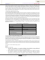
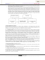
1585 Vol 06, Article 08622; August 2015 http://ijves.com International Journal of VLSI and Embedded Systems-IJVES ISSN: 2249 – 6556 IMPLEMENTATION OF COACH GUIDANCE DISPLAY SYSTEM SIRISHA KUNISETTI Embedded System, CVR College of Engineering,Vastunagar,Mangalpalli(V),Ibrahimpatanam(M),R.R Dist, Telangana,India [email protected] ABSTRACT The aim of the project is implementation of the Coach Guidance Display System for railway stations. The Coach Guidance Display System is the combination of cortex microcontroller kit and SMD LED (Surface Mount Device light Emitting Diode) display board. The 32 bit microcontroller is used to meet the specifications of Research Design and Standard Organization (RDSO). This project involves embedded communication in point to point network. The principle used in the project is serial communication using RS-232 and RS-485. Dedicated links made easy to meet real-time deadlines. The Coach Guidance Display System mainly for easy identification of coach positions by passengers. These are required to display train number and coach number alternatively. Once a user operating the application software selects a particular train and its coach composition, and sends it on the network, then each Coach Guidance Display Board has to display the coach name appropriately. The coach number may be displayed in multiple languages. Individual coach display board across the platform show the position of the coaches like GEN, D1, S10, B1, A1, H1 in English and “अना., डी-1, एस-10, बी-1, ए-1, एच-1”etc. and train number. Intensity control of coach guidance display board shall be made 25%. These boards are installed throughout the platform at appropriate locations, such that one display board will be there corresponding to each coach position. There can be a maximum of 26 coaches for passenger trains as of now and hence the same number of Coach Guidance Display Boards required per platform . Full papers are expected to be between 6 pages (minimum) and 8 pages (normal maximum) in length. Please use this as a template for your paper. [1] INTRODUCTION The Objective of this project is implementation of the Coach Guidance Display System for railway stations. The Coach Guidance Display System is the combination of cortex microcontroller kit and SMD LED (Surface Mount Device light Emitting Diode) display board. This is for easy identification of coach positions by passengers. These are required to display train number and coach number alternatively. Applications involving the Implementation of the CGDB presented in this project All the display boards should be given unique identification code/address & their status is to be reflected and made available on screen of the operating console as a health monitoring indication. Surge and lightening protection arrangement should be provided at 230V AC mains end and output of power supply, so as to protect the electronic modules from damage. The arrangement may include GD tubes, MOVs and fuses etc. The, STM32F100x8 microcontrollers incorporate the high-performance ARMCortexM3 32-bit RISC core operating at a 24 MHz frequency, high-speed embedded memories (Flash memory up to 128 Kbytes and SRAM up to 8 Kbytes), and an extensive range of enhanced peripherals and I/Os connected to two APB buses. Device offer standard communication interfaces (up to two I2Cs, two SPIs, one HDMI CEC, and up to three USARTs), one 12-bit ADC, two 12-bit DACs, up to six general-purpose 16-bit timers and an advanced-control PWM timer.A comprehensive set of power-saving mode allows the design of low-power applications. The microcontroller include device in package with 48 pins. Depending on the device chosen, different sets of peripherals are included. These features make these microcontrollers suitable for a wide range of applications such as application control and user interfaces, medical and hand-held equipment, PC and gaming peripherals, GPS platforms, industrial applications, PLCs, inverters, printers, scanners, alarm systems, video intercoms, and HVACs. 2. TECHNICAL DETAILS OF COACH GUIDANCE DISPLAY SYSTEM Coach guidance display boards are fixed on each platform in railway station. The data for these display boards shall be entered, and controlled from a central place. The network architecture specified is to cater the railway environment and conditions like railway electric traction, disturbances etc. The data to all the systems, both information & coach composition are disseminated and routed in the network. For this Main Data Communication Hub and Platform Data Communication Hub are placed in the network. Let us now have a look at the installation technology of coach guidance display boards. The coach guidance LED display boards for individual coaches should be hanged from the metallic structure of the platform roof or by 2010-2015 – IJVES Indexing in Process - EMBASE, EmCARE, Electronics & Communication Abstracts, SCIRUS, SPARC, GOOGLE Database, EBSCO, NewJour, Worldcat, DOAJ, and other major databases etc., 1586 Vol 06, Article 08622; August 2015 http://ijves.com International Journal of VLSI and Embedded Systems-IJVES ISSN: 2249 – 6556 suitable fixing arrangement. Mechanical fixing arrangement for installation of double face LED display board should be either designed to prevent swinging of LED display boards due to strong wind / vibration due to movement of the trains or on separate pole with protection against rain. Wherever platform rooftop is not available the coach guidance display board should be fitted in staggering form at end of the platform shade to the extent possible to display coach position of such coaches. The Console (PC based) should be installed at the control tower / station master room or Enquiry Room. It should have required software and provision of data entry for coach positions of trains from remote site. 2.1 The Coach Guidance Display System: Ease of maintenance and immunity to failures should be the primary consideration in the design of the system. The system should employ tin-electroplated glass epoxy printed circuit boards and the PCBs should be secured firmly to ensure that the no loose connection results from vibration. As this display should work round the clock, it is desirable that component used should be of industrial grade & standard. All the ICs should be fitted preferably on proper base so that replacement of faulty ICs can be done at site immediately without using soldering iron. The equipment should be mounted in metallic housing of industrial grade to avoid entry of dust and rise of temperature with necessary earthing etc. to provide complete EMI & RFI protection. LED Display board used is multiplexed and works on principle of Persistence of vision. The LED matrix used in this experiment is of size 16×48. Hardware involved is74HCT245 Buffer which is used to drive The LEDS, TLC59282 Shift Register is used for pumping, latching data and driving the output buffer, Multiplexing is performed by 3*8 Decoder for selecting appropriate columns. Table below describes the dimensions of the Display board used here. Table 1. Dimensions of Display Board Matrix Size (LxDxH) mm 600 X 230 X300 Pixel Size 3 mm Pixel Pitch 10mm Pixel colour White Character Height 160mm LED Brightness 600 mcd Viewing Angle Hor: 110°, Ver: 40° Viewing Distance Up to 50 mts Power Supply 160 to 270 VAC Operating Temperature -10° to +70°C 2.1.1 Description of Coach guidance Display System. Communication from computer to microcontroller is possible using RS-232 to Rs-485 converter because the CPU does not have an RS-485 pin. The CGDB control card uses the STM32F100c8 Microcontroller for the purpose of application control and interface. Integrating the microcontroller and some additions the system is modified to work as a better communication network. Development of the software and hardware is carried out by monitoring the response times of the embedded system. The block diagram in the Fig. 1, describes implementation of Coach Guidance Display system. The System is the combination of cortex microcontroller kit and SMD LED (Surface Mount Device light Emitting Diode) display board. The 32 bit microcontroller is used to meet the specifications of Research Design and Standard Organization (RDSO). Itemised list of Coach Guidance Display System: ST Link RS-485 RS-232 to 485 Converter. ST Link. The ST-LINK is an in-circuit debugger and programmer for the STM8 and STM32microcontroller families. The SWIM and JTAG/SWD interface is used to communicate with the STM8 or STM32 microcontroller located on our own application board. RS 485. RS-485 is an electrical-only standard. In contrast to complete interface standards, which define the functional, mechanical, and electrical specifications, RS-485 only defines the electrical characteristics of drivers and receivers that could be used to implement a balanced multipoint transmission line.This standard, however, is intended to be referenced by higher level standards, such as 2010-2015 – IJVES Indexing in Process - EMBASE, EmCARE, Electronics & Communication Abstracts, SCIRUS, SPARC, GOOGLE Database, EBSCO, NewJour, Worldcat, DOAJ, and other major databases etc., 1587 Vol 06, Article 08622; August 2015 http://ijves.com International Journal of VLSI and Embedded Systems-IJVES ISSN: 2249 – 6556 DL/T645, for example, which defines the communication protocol for electronic energy-meters in China, specifyingRS-485 as the physical layer standard. RS-232 to 485 Converter. The RS 232 to 485 converters are very much essential in this project because a Personal Computer does not have the RS 485 port. RS232/CMOS to RS422/RS485 Converter converts RS232/CMOS lines to balanced RS422 or RS485 signals. RS232/CMOS to RS422/RS485 converter is available in two models,CNV-01 and CNV-02-B. Power is isolated from communication ports in CNV01 model, whereas communication ports are not isolated.The converter is a port-powered (line-powered: RXD+RTS+CTS) or externally powered. In case of point to point communication and if the cable length is less than or equal to 2 meter, at RS232side, then external power supply is not needed. This unit takes less than 4mA to operate plus load current. Applications which require a large load current, external+24VDC power supply on the terminal strip is required. Fig.1. Descriptive block diagram of Coach Guidance Display System . 3. SOFTWARE EXPLANATION The Keil IDE plays the important role in software support. Embedded C is the language mainly used. Dotnet application is also used for data format. Visual soft application software is used in entering the bitmaps (in case of displaying other languages). Keil and the tools required are mainly discussed here. 3.1 Keil Environment. Keil tools are used for the project development cycle is and it is similar to any other software development project. Create a project, select the target device from the Device Data base, and configure the tool settings. The µVision IDE is a window-based software development platform combining a robust editor, Project Manager, and Make Utility tool. µVision supports all the Keil tools including C/C++ Compiler, Macro Assembler, Linker, Library Manager, and Object-HEX Converter. The µVision Device Database offers a convenient way to select and configure your device and project parameters. It includes preconfigured settings, so that you can fully concentrate on your application requirements. In addition, you can add your own devices, or change existing settings. Use the features of the Device Database to: Initialize the start up code and device settings, load the configuration options for the assembler, compiler, and linker, and you can add and change microcontroller configuration settings The µVision Debugger is completely integrated into the µVision IDE. The dialog Debug defines options that apply when a debugging session is started. The screen is split into options for the Simulator and for the target driver. Two debugging modes can be selected and configured in the dialog Options for Target. Debug: Use Simulator, configures the µVision Debugger as software-only product that simulates most features of a microcontroller. The µVision Debugger simulates all aspects of a UART including accurate serial communications timing. UART configuration parameters display in the UART Peripheral Dialog. 3.2 Sender side Working:In SendData() Function A buffer byte[] byteToSend is initialized with Message Format i.e. {0xAA, 0xCC, 0x01, 0x10, 0x01, 0x10, 0x10, 0x11, 0x01,0x80,0x95 } Then from index2 of byteToSend, copying all data to a sbuffer and passed it to ComputeChecksumBytes() to get the CRC-16 Encoding Value. CheckSum Value is created based on the message format. On getting CheckSum Values back, append with buffer byteToTransfer, which comprised of {0xAA, 0xCC, 0x01, 0x10, 0x01, 0x10, 0x10, 0x11, 0x01,0x80,0x95,WX,YZ } Where WX,YZ: are CRC value generated on passing it to ComputeChecksumBytes() function. Now the message format is ready to be transmitted. 2010-2015 – IJVES Indexing in Process - EMBASE, EmCARE, Electronics & Communication Abstracts, SCIRUS, SPARC, GOOGLE Database, EBSCO, NewJour, Worldcat, DOAJ, and other major databases etc., 1588 Vol 06, Article 08622; August 2015 http://ijves.com International Journal of VLSI and Embedded Systems-IJVES ISSN: 2249 – 6556 After sending this buffer, Receiver gets the whole packet and Computer Checksum on his side. If it’s Correct receiver sends back a Reply Message Format. Sender receives it and does Computer Checksum. If it’s Correct, It displays “CRC has been verified” 3.3 Receiver side Working. Enable/disable the discarding of received packets for which the CRC verification has failed. When this feature is enabled, the library automatically removes the CRC bytes from the packets that passed the CRC verification: ST_EnableReceive crc(TRUE); When the address filtering mode is enabled, perform the following actions: Set the radio PAN identifier:uint16_tpanid = USER_PAN_ID; /* set the panid for filtering received packets */ ST_SetPanId(panid); Set the node identifier if the user application requires filtering on the 16-bit short address (or node identifier):uint16_tnodeid = USER_NODE_ID; /*set the nodeid (short address) for filtering received packets*/ ST_SetNodeID(nodeid); processReceivedPackets(void) prints the data that is received in uint8_t rxPacket[128] variable. This function is called in While loop. The function in turn checks packetReceived variable which is set by ST_ReceiveIsrCallback() when data arrives. ST_ReceiveIsrCallback() is a call-back function called by Simple MAC library when data arrives. It is via interrupt mechanisms. 3.4 Communication. For CGDBs the display information is bundled into a single packet for all coaches information of a particular train on designated platform; and will be sent to the respective PDCH of the platform (or even to a MDCH as the case may be), after sending all CGDBs connected ports enable command to the same HUB. Hence this entire packet will be circulated to all the CGDBs of that particular platform. Further each CGDB will pick up train number (from a fixed location in the packet) and coach string with respect to its board id (which corresponds to its physical position from first CGDB of the platform). No responses will be generated from any of the CGDBs, as this will give rise to collisions among competing transmitters. The application software has to ensure by some means that the packet has reached correctly to the destination. This can be done by issuing previous command status function code and analyzing its responses from each individual boards to whom reception has to be ensured. Display Timeout Value gives the time out value of the data present on the CGDB in minutes. Data on CGDB will be cleared after no activity from application (i.e. no command packet received, etc.) for this duration of time. The response for the configuration settings is given by the CGDB 3.5 Docklight. For RS232 full-duplex monitoring applications, recommend the Docklight Tap USB accessory, or our Docklight Monitoring Cable is recommended. Docklight is a testing, analysis and simulation tool for serial communication protocols (RS232, RS485/422 and others). It allows you to monitor communications between two serial devices or to test the serial communication of a single device. Docklight is easy to use and works on almost any standard PC running Windows8, Windows7, Windows Vista and Windows XP. Docklight's key functions include simulating serial protocols - Docklight can send out user-defined sequences according to the protocol used and it can react to incoming sequences. 4. CONCLUSIONS Implementation of Coach Guidance Display System is done using Dot Net Framework and IPIS Configuration Bytes. The result is error free display with desired brightness. The IPIS application allows to send the data to the display board.The start of application window has the details to be selected by the user,as per their use. There it has the configuration settings and intensity settings for the user.The application window also holds details status of the data transmission and COM port detailsand it has the complete details of the train. The arrival/departure and time its platform number theseall details can be selected by the user.Type of display is also one of the option provided in the IPIS application window.The user can choose Train Arrival Departure Display board(TADDB) or the Coach Guidance Display Board(CGDB). The main aim is for easy identification of coach positions by passengers is achieved. Using Keil IDE the code can be ported on Coach Guidance Display Board’s control card. The combination of cortex microcontroller kit and SMD LED display board displayed the train number and coach number alternatively. The coach position is displayed in multiple languages. Individual coach display board across the platform shown the position of the coaches like GEN, D1, S10, B1, A1, H1 in English and “अना., डी-1, एस-10, बी-1, ए-1, एच1”etc. and train number. Intensity control of coach guidance display board is made 25%.Implementation of Coach Guidance Display System helps in learning Display Board Concepts that are used in Railways. 2010-2015 – IJVES Indexing in Process - EMBASE, EmCARE, Electronics & Communication Abstracts, SCIRUS, SPARC, GOOGLE Database, EBSCO, NewJour, Worldcat, DOAJ, and other major databases etc., 1589 Vol 06, Article 08622; August 2015 http://ijves.com International Journal of VLSI and Embedded Systems-IJVES ISSN: 2249 – 6556 ACKNOWLEDGEMENTS First and foremost I express my deep sense of gratitude to the Almighty which cannot be described in words, for the blessings and strength the GOD has showered on me in fulfilling my aspirations. I wish to express my deepest gratitude and thanks to Principal Dr. K.S NAYANATHARA for her constant support and encouragement. At the outset, I am very much indebted to the Management of CVR COLLEGE OF ENGINEERING AND TECHNOLOGY (CVRCE) for the valuable education imparted to me in the successful completion of the M.Tech (Embedded Systems) Course for award of Masters Degree. I would like to express my gratitude to Wg Cdr Vargheese Thattil, Head of the Department, E.C.E, and Dr. Humaira Nishat, PG coordinator for their valuable support which has been helpful in the completion of this course. I would like to express my sincere gratitude to Prof. C.V.Rao and Dr.P. Subrahmanyam, for their valuable guidance, comments, suggestions and encouragement for the completion of this project. I wish to thank Mrs.Rinku R Dhruva, Associate Professor for her valuable time and guidance extended to me during the period of project execution. I wish to express my thanks to Asst. Prof S. Sailaja, Coordinator of M.Tech for extreme help and support given to complete the project. Though no words can express my gratitude to my family without which support and encouragement this achievement would not have been possible. I also express my thanks to the staff of ARECA EMEDDED SYSTEMS Pvt ltd, IDA Cherlapalli for allowing me to complete my project there as an Intern. I thank my friends and my classmates who have extended their co-operation in this regard. REFERENCES [1] STM32F100xx Manual Datasheet. [2] http://stackoverflow.com/questions/815758/simple-serial-point-to-point-communication-protocol. [3] RDSO SPECIFICATION FOR INTEGRATED PASSENGER INFORMATION SYSTEM. [4] Insider’s Guide STM32 to The ARM Based Microcontroller. HITEX [5] UM0627 User manual ST-LINK in-circuit debugger/programmer for STM8 and STM32 microcontrollers 2010-2015 – IJVES Indexing in Process - EMBASE, EmCARE, Electronics & Communication Abstracts, SCIRUS, SPARC, GOOGLE Database, EBSCO, NewJour, Worldcat, DOAJ, and other major databases etc.,