1
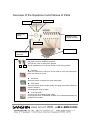
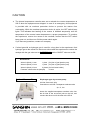
DEOXYGENIZED GAS PRESSURE REPLACE GR-8 User’s Manual Overview of the Equipment and Names of Parts OK lamp ON switch OFF switch Compound gauge ON/OFF valves (Toggle switches) Gas valve Luer lock holder Gas introduction nylon tube ON OFF ON/OFF valves (toggle switches) ON (Open): Lever is straight to the panel OFF (Close): Lever is at the down position These rotatable levers can be turned ON or OFF at any position. OK lamp When the equipment is turned on and is ready to work, this yellow lamp lights with electronic sound. ON switch When this switch is pressed, the green lamp lights. OFF switch The internal lamp does not light usually, but lights momentarily when this switch is pressed. The lamp lights red at an alarm. Luer lock holder Connect a luer lock needle to this holder. A syringe filter such as DISMICR or Millex can be attached between the needle and the holder. Using the Equipment 1. Connect the vacuum pump to the VACUUM PUMP hose port on the left panel of the GR-8 with a hose. Standard type: Connect a vacuum exhaust hose to the hose port. Vacuum pump option type: Insert the supplied transparent urethane tube into the one-touch joint. To disconnect the tube, pull it while pushing the blue ring of the joint. 2. Connect the GR-8 to the gas pipe to be used for experiment with the black tube under the MIXED GAS label on the left panel through the pressure regulator. A PT 1/8 male screw and a PT 1/8 female screw at the end of the black nylon tube are attached to the gas pipe connector of the GR-8. If you do not have a compliant connector on the gas pressure regulator side or you have any questions, contact our company. Set the pressure regulator on the secondary side of the gas pipe to 0.2 Mpa. 3. When gas connection is completed, set the gas valve to CLOSE and turn ON the power switch. The ON switch lamp lights green and the GR-8 starts warming up. 4. Upon completion of the warming-up, the OK lamp lights yellow with electronic sound. The GR-8 is ready for work. 5. Turn ON the vacuum pump switch. 6. Set an injection needle to the pressure culture tube or a culture vessel. Set the ON/OFF valve (black toggle switch) to ON. 7. Set the gas valve to VACUUM. Check that the compound gauge indicates -0.1 Mpa. 8. Set the gas valve to O2 FREE GAS. 9. Switch the gas valve from VACUUM to O2 FREE GAS and repeat this switching twice or three times to completely replace the air in the vessel. After that, set the ON/OFF valve to OFF and set the gas valve to CLOSE. 10. To shut down the GR-8, (1) Close the gas cylinder. (2) Turn OFF the vacuum pump switch. (3) Press the red OFF switch to turn OFF the power. CAUTION ● The internal temperature controller was set to maintain the reactor temperature at 220°C when the equipment was shipped. In case of an emergency, this equipment is provided with an overheat prevention device to prevent the reactor from overheating. While the overheat prevention device is active, the OFF switch lamp lights. This indicates that heating of the reactor is inhibited temporarily until the temperature of the reactor heater decreases to a proper temperature. To continue the experiment, remove the cause of the overheat, confirm that the OFF switch lamp goes out, and then turn ON the power switch again. If you have any questions, contact our company. ● If mixed gas with no hydrogen gas is used for a long time in the experiment, feed hydrogen gas to the reactor for about one minute after the experiment to reduce the catalyst with the gas valve set to O2 FREE GAS and the ON/OFF valve set to ON. Accessories Wrench (black) 11 mm 1 piece (for joint of gas injection port) Wrench (black) 13 mm 1 piece (for joint of gas injection port) Wrench (black) 12 mm 2 pieces (for lock base holder) Pressure culture tube set (sample) Optional Vacuum Pump 10 sets Diaphragm-type dry vacuum pump Air inlet: One-touch joint Connection to air inlet: Transparent urethane tube φ8 × 5, 2 m Insert the supplied transparent urethane tube into the air inlet of the one-touch joint on the left, and connect the other end of the tube to the GR-8.