1
DL06 IBox Instructions
PLC User Manual Supplement
Manual Number: DL06-IBOX-S
WARNING
Thank you for purchasing automation equipment from Automationdirect.com™, doing business as
AutomationDirect. We want your new automation equipment to operate safely. Anyone who installs or
uses this equipment should read this publication (and any other relevant publications) before installing or
operating the equipment.
To minimize the risk of potential safety problems, you should follow all applicable local and national
codes that regulate the installation and operation of your equipment. These codes vary from area to area
and usually change with time. It is your responsibility to determine which codes should be followed, and
to verify that the equipment, installation, and operation is in compliance with the latest revision of these
codes.
At a minimum, you should follow all applicable sections of the National Fire Code, National Electrical
Code, and the codes of the National Electrical Manufacturer's Association (NEMA). There may be local
regulatory or government offices that can also help determine which codes and standards are necessary
for safe installation and operation.
Equipment damage or serious injury to personnel can result from the failure to follow all applicable codes
and standards. We do not guarantee the products described in this publication are suitable for your
particular application, nor do we assume any responsibility for your product design, installation, or
operation.
Our products are not fault-tolerant and are not designed, manufactured or intended for use or resale as
on-line control equipment in hazardous environments requiring fail-safe performance, such as in the
operation of nuclear facilities, aircraft navigation or communication systems, air traffic control, direct life
support machines, or weapons systems, in which the failure of the product could lead directly to death,
personal injury, or severe physical or environmental damage ("High Risk Activities"). AutomationDirect
specifically disclaims any expressed or implied warranty of fitness for High Risk Activities.
For additional warranty and safety information, see the Terms and Conditions section of our catalog. If
you have any questions concerning the installation or operation of this equipment, or if you need
additional information, please call us at 770-844-4200.
This publication is based on information that was available at the time it was printed. At
AutomationDirect we constantly strive to improve our products and services, so we reserve the right to
make changes to the products and/or publications at any time without notice and without any
obligation. This publication may also discuss features that may not be available in certain revisions of the
product.
Trademarks
This publication may contain references to products produced and/or offered by other companies. The
product and company names may be trademarked and are the sole property of their respective owners.
AutomationDirect disclaims any proprietary interest in the marks and names of others.
Copyright 2006, Automationdirect.com™ Incorporated
All Rights Reserved
No part of this manual shall be copied, reproduced, or transmitted in any way without the prior, written
consent of Automationdirect.com™ Incorporated. AutomationDirect retains the exclusive rights to all
information included in this document.
AVERTISSEMENT
Nous vous remercions d'avoir acheté l'équipement d'automatisation de Automationdirect.com™, en faisant des
affaires comme AutomationDirect. Nous tenons à ce que votre nouvel équipement d'automatisation fonctionne en
toute sécurité. Toute personne qui installe ou utilise cet équipement doit lire la présente publication (et toutes les
autres publications pertinentes) avant de l'installer ou de l'utiliser.
Afin de réduire au minimum le risque d'éventuels problèmes de sécurité, vous devez respecter tous les codes locaux et
nationaux applicables régissant l'installation et le fonctionnement de votre équipement. Ces codes diffèrent d'une
région à l'autre et, habituellement, évoluent au fil du temps. Il vous incombe de déterminer les codes à respecter et
de vous assurer que l'équipement, l'installation et le fonctionnement sont conformes aux exigences de la version la
plus récente de ces codes.
Vous devez, à tout le moins, respecter toutes les sections applicables du Code national de prévention des incendies,
du Code national de l'électricité et des codes de la National Electrical Manufacturer's Association (NEMA). Des
organismes de réglementation ou des services gouvernementaux locaux peuvent également vous aider à déterminer
les codes ainsi que les normes à respecter pour assurer une installation et un fonctionnement sûrs.
L'omission de respecter la totalité des codes et des normes applicables peut entraîner des dommages à l'équipement
ou causer de graves blessures au personnel. Nous ne garantissons pas que les produits décrits dans cette publication
conviennent à votre application particulière et nous n'assumons aucune responsabilité à l'égard de la conception, de
l'installation ou du fonctionnement de votre produit.
Nos produits ne sont pas insensibles aux défaillances et ne sont ni conçus ni fabriqués pour l'utilisation ou la revente
en tant qu'équipement de commande en ligne dans des environnements dangereux nécessitant une sécurité absolue,
par exemple, l'exploitation d'installations nucléaires, les systèmes de navigation aérienne ou de communication, le
contrôle de la circulation aérienne, les équipements de survie ou les systèmes d'armes, pour lesquels la défaillance du
produit peut provoquer la mort, des blessures corporelles ou de graves dommages matériels ou environnementaux
(«activités à risque élevé»). La société AutomationDirect nie toute garantie expresse ou implicite d'aptitude à l'emploi
en ce qui a trait aux activités à risque élevé.
Pour des renseignements additionnels touchant la garantie et la sécurité, veuillez consulter la section Modalités et
conditions de notre documentation. Si vous avez des questions au sujet de l'installation ou du fonctionnement de cet
équipement, ou encore si vous avez besoin de renseignements supplémentaires, n'hésitez pas à nous téléphoner au
770-844-4200.
Cette publication s'appuie sur l'information qui était disponible au moment de l'impression. À la société
AutomationDirect, nous nous efforçons constamment d'améliorer nos produits et services. C'est pourquoi nous nous
réservons le droit d'apporter des modifications aux produits ou aux publications en tout temps, sans préavis ni
quelque obligation que ce soit. La présente publication peut aussi porter sur des caractéristiques susceptibles de ne
pas être offertes dans certaines versions révisées du produit.
Marques de commerce
La présente publication peut contenir des références à des produits fabriqués ou offerts par d'autres entreprises. Les
désignations des produits et des entreprises peuvent être des marques de commerce et appartiennent exclusivement à
leurs propriétaires respectifs. AutomationDirect nie tout intérêt dans les autres marques et désignations.
Copyright 2006, Automationdirect.com™ Incorporated
Tous droits réservés
Nulle partie de ce manuel ne doit être copiée, reproduite ou transmise de quelque façon que ce soit sans le
consentement préalable écrit de la société Automationdirect.com™ Incorporated. AutomationDirect conserve les
droits exclusifs à l'égard de tous les renseignements contenus dans le présent document.
DirectSOFT5 IBox Instructions for DL06 PLCs
Overview
1
2
3
4
S
6
7
8
9
10
11
12
13
14
A
B
C
D
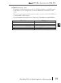
The Ibox Instructions listed in this supplement are in addition to the Standard RLL
Instructions found in Chapter 5 of the DL06 User Manual. These new instructions are
available when using DirectSOFT5 to program your DL06 PLC (the DL06 CPU requires
firmware version v2.10 or later to use the new features in DirectSOFT5). For more
information on DirectSOFT5 and to download our Free version, please visit our Web site at:
www.automationdirect.com
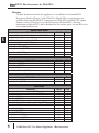
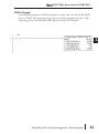
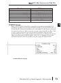
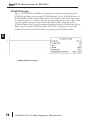
Analog Helper IBoxes
Instruction
Ibox #
Page
Analog Input / Output Combo Module Pointer Setup (ANLGCMB)
Analog Input Module Pointer Setup (ANLGIN)
Analog Output Module Pointer Setup (ANLGOUT)
Analog Scale 12 Bit BCD to BCD (ANSCL)
Analog Scale 12 Bit Binary to Binary (ANSCLB)
Filter Over Time - BCD (FILTER)
Filter Over Time - Binary (FILTERB)
Hi/Low Alarm - BCD (HILOAL)
Hi/Low Alarm - Binary (HILOALB)
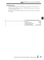
Discrete Helper IBoxes
Instruction
Off Delay Timer (OFFDTMR)
On Delay Timer (ONDTMR)
One Shot (ONESHOT)
Push On / Push Off Circuit (PONOFF)
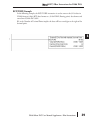
Memory IBoxes
Instruction
Move Single Word (MOVEW)
Move Double Word (MOVED)
Math IBoxes
Instruction
BCD to Real with Implied Decimal Point (BCDTOR)
Double BCD to Real with Implied Decimal Point (BCDTORD)
Math - BCD (MATHBCD)
Math - Binary (MATHBIN)
Math - Real (MATHR)
Real to BCD with Implied Decimal Point and Rounding (RTOBCD)
Real to Double BCD with Implied Decimal Point and Rounding (RTOBCDD)
Square BCD (SQUARE)
Square Binary (SQUAREB)
Square Real(SQUARER)
Sum BCD Numbers (SUMBCD)
Sum Binary Numbers (SUMBIN)
Sum Real Numbers (SUMR)
4
IB-462
IB-460
IB-461
IB-423
IB-403
IB-422
IB-402
IB-421
IB-401
6
8
10
12
14
16
18
20
22
Ibox #
Page
IB-302
IB-301
IB-303
IB-300
24
26
28
30
Ibox #
Page
IB-200
IB-201
32
34
Ibox #
Page
IB-560
IB-562
IB-521
IB-501
IB-541
IB-561
IB-563
IB-523
IB-503
IB-543
IB-522
IB-502
IB-542
36
38
40
42
44
46
48
50
52
54
56
58
60
DL06 Micro PLC User Manual Supplement - IBox Instructions
DirectSOFT5 IBox Instructions for DL06 PLCs
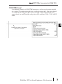
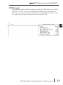
Communication IBoxes
Instruction
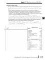
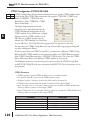
ECOM100 Configuration (ECOM100)
ECOM100 Disable DHCP (ECDHCPD)
ECOM100 Enable DHCP (ECDHCPE)
ECOM100 Query DHCP Setting (ECDHCPQ)
ECOM100 Send E-mail (ECEMAIL)
ECOM100 Restore Default E-mail Setup (ECEMRDS)
ECOM100 E-mail Setup (ECEMSUP)
ECOM100 IP Setup (ECIPSUP)
ECOM100 Read Description (ECRDDES)
ECOM100 Read Gateway Address (ECRDGWA)
ECOM100 Read IP Address (ECRDIP)
ECOM100 Read Module ID (ECRDMID)
ECOM100 Read Module Name (ECRDNAM)
ECOM100 Read Subnet Mask (ECRDSNM)
ECOM100 Write Description (ECWRDES)
ECOM100 Write Gateway Address (ECWRGWA)
ECOM100 Write IP Address (ECWRIP)
ECOM100 Write Module ID (ECWRMID)
ECOM100 Write Name (ECWRNAM)
ECOM100 Write Subnet Mask (ECWRSNM)
ECOM100 RX Network Read (ECRX)
ECOM100 WX Network Write(ECWX)
NETCFG Network Configuration (NETCFG)
Network RX Read (NETRX)
Network WX Write (NETWX)
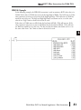
Counter I/O IBoxes
Instruction
CTRIO Configuration (CTRIO)
CTRIO Add Entry to End of Preset Table (CTRADPT)
CTRIO Clear Preset Table (CTRCLRT)
CTRIO Edit Preset Table Entry (CTREDPT)
CTRIO Edit Preset Table Entry and Reload (CTREDRL)
CTRIO Initialize Preset Table (CTRINPT)
CTRIO Initialize Preset Table (CTRINTR)
CTRIO Load Profile (CTRLDPR)
CTRIO Read Error (CTRRDER)
CTRIO Run to Limit Mode (CTRRTLM)
CTRIO Run to Position Mode (CTRRTPM)
CTRIO Velocity Mode (CTRVELO)
CTRIO Write File to ROM (CTRWFTR)
Ibox #
Page
IB-710
IB-736
IB-735
IB-734
IB-711
IB-713
IB-712
IB-717
IB-726
IB-730
IB-722
IB-720
IB-724
IB-732
IB-727
IB-731
IB-723
IB-721
IB-725
IB-733
IB-740
IB-741
IB-700
IB-701
IB-702
62
64
66
68
70
73
76
80
82
84
86
88
90
92
94
96
98
100
102
104
106
109
112
114
117
Ibox #
Page
IB-1000
IB-1005
IB-1007
IB-1003
IB-1002
IB-1004
IB-1010
IB-1001
IB-1014
IB-1011
IB-1012
IB-1013
IB-1006
120
122
125
128
132
136
140
144
147
149
152
155
158
DL06 Micro PLC User Manual Supplement - IBox Instructions
1
2
3
4
S
6
7
8
9
10
11
12
13
14
A
B
C
D
5
DirectSOFT5 IBox Instructions for DL06 PLCs
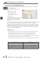
Analog Input/Output Combo Module Pointer Setup (ANLGCMB) (IB-462)
1
2
3
4
S
6
7
8
9
10
11
12
13
14
A
B
C
D
DS5
Used
HPP
N/A
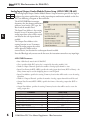
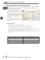
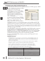
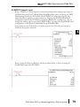
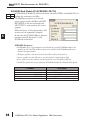
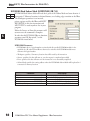
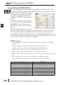
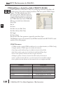
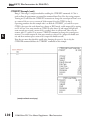
The Analog Input/Output Combo Module Pointer Setup instruction generates the logic to
configure the pointer method for an analog input/output combination module on the first
PLC scan following a Program to Run transition.
The ANLGCMB IBox instruction
determines the data format and Pointer
addresses based on the CPU type, the
Base# and the module Slot#.
The Input Data Address is the starting
location in user V-memory where the
analog input data values will be stored,
one location for each input channel
enabled.
The Output Data Address is the
starting location in user V-memory
where the analog output data values
will be placed by ladder code or
external device, one location for each output channel enabled.
Since the IBox logic only executes on the first scan, the instruction cannot have any input logic.
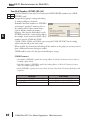
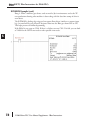
ANLGCMB Parameters
• Base # (K0-Local): must be 0 for DL06 PLC
• Slot #: specifies which PLC option slot is occupied by the analog module (1–4)
• Number of Input Channels: specifies the number of analog input channels to scan
• Input Data Format (0-BCD 1-BIN): specifies the analog input data format (BCD or Binary) - the
binary format may be used for displaying data on some OI panels
• Input Data Address: specifies the starting V-memory location that will be used to store the analog
input data
• Number of Output Channels: specifies the number of analog output channels that will be used
• Output Data Format (0-BCD 1-BIN): specifies the format of the analog output data (BCD or
Binary)
• Output Data Address: specifies the starting V-memory location that will be used to source the
analog output data
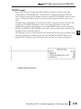
Parameter
Base # (K0-Local) . . . . . . . . . . . . . . . . . . . . . . . K
Slot # . . . . . . . . . . . . . . . . . . . . . . . . . . . . . . . . . K
Number of Input Channels . . . . . . . . . . . . . . . . K
Input Data Format (0-BCD 1-BIN) . . . . . . . . . . . K
Input Data Address . . . . . . . . . . . . . . . . . . . . . . V
Number of Output Channels . . . . . . . . . . . . . . . K
Output Data Format (0-BCD 1-BIN) . . . . . . . . . K
Output Data Address . . . . . . . . . . . . . . . . . . . . . V
6
DL06 Range
K0 (local base only)
K1-4
K1-8
BCD: K0; Binary: K1
See DL06 V-memory map - Data Words
K1-8
BCD: K0; Binary: K1
See DL06 V-memory map - Data Words
DL06 Micro PLC User Manual Supplement - IBox Instructions
DirectSOFT5 IBox Instructions for DL06 PLCs
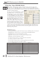
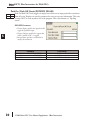
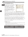
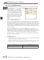
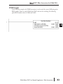
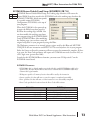
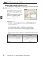
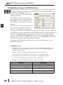
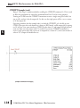
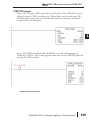
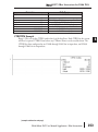
ANLGCMB Example
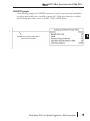
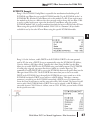
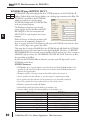
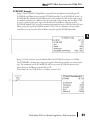
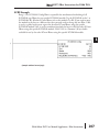
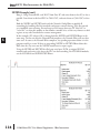
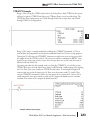
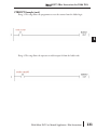
In the following example, the ANLGCMB instruction is used to setup the pointer method
for an analog I/O combination module that is installed in option slot 2. Four input channels
are enabled and the analog data will be written to V2000 - V2003 in BCD format. Two
output channels are enabled and the analog values will be read from V2100 - V2101 in BCD
format.
No permissive contact or input logic is
used with this instruction
DL06 Micro PLC User Manual Supplement - IBox Instructions
7
1
2
3
4
S
6
7
8
9
10
11
12
13
14
A
B
C
D
DirectSOFT5 IBox Instructions for DL06 PLCs
Analog Input Module Pointer Setup (ANLGIN) (IB-460)
1
2
3
4
S
6
7
8
9
10
11
12
13
14
A
B
C
D
DS5
Used
HPP
N/A
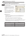
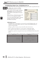
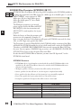
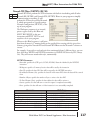
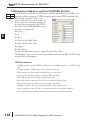
Analog Input Module Pointer Setup generates the logic to configure the pointer method for
one analog input module on the first PLC scan following a Program to Run transition.
This IBox determines the data format
and Pointer addresses based on the
CPU type, the Base#, and the Slot#.
The Input Data Address is the starting
location in user V-memory where the
analog input data values will be stored,
one location for each input channel
enabled.
Since this logic only executes on the
first scan, this IBox cannot have any
input logic.
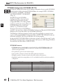
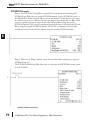
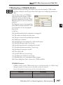
ANLGIN Parameters
• Base # (K0-Local): must be 0 for DL06 PLC
• Slot #: specifies which PLC option slot is occupied by the analog module (1–4)
• Number of Input Channels: specifies the number of input channels to scan
• Input Data Format (0-BCD 1-BIN): specifies the analog input data format (BCD or Binary) - the
binary format may be used for displaying data on some OI panels
• Input Data Address: specifies the starting V-memory location that will be used to store the analog
input data
Parameter
Base # (K0-Local) . . . . . . . . . . . . . . . . . . . . . . . K
Slot # . . . . . . . . . . . . . . . . . . . . . . . . . . . . . . . . . K
Number of Input Channels . . . . . . . . . . . . . . . . K
Input Data Format (0-BCD 1-BIN) . . . . . . . . . . . K
Input Data Address . . . . . . . . . . . . . . . . . . . . . . V
8
DL06 Range
K0 (local base only)
K1-4
K1-8
BCD: K0; Binary: K1
See DL06 V-memory map - Data Words
DL06 Micro PLC User Manual Supplement - IBox Instructions
DirectSOFT5 IBox Instructions for DL06 PLCs
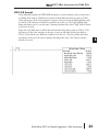
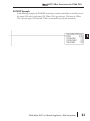
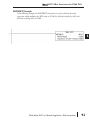
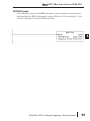
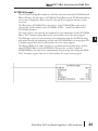
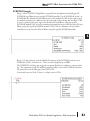
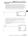
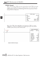
ANLGIN Example
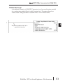
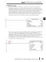
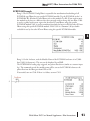
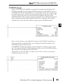
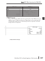
In the following example, the ANLGIN instruction is used to setup the pointer method for
an analog input module that is installed in option slot 1. Eight input channels are enabled
and the analog data will be written to V2000 - V2007 in BCD format.
1
2
3
4
S
6
7
8
9
10
11
12
13
14
A
B
C
D
No permissive contact or input logic is
used with this instruction
DL06 Micro PLC User Manual Supplement - IBox Instructions
9
DirectSOFT5 IBox Instructions for DL06 PLCs
Analog Output Module Pointer Setup (ANLGOUT) (IB-461)
1
2
3
4
S
6
7
8
9
10
11
12
13
14
A
B
C
D
DS5
HPP
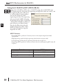
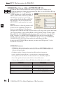
Analog Output Module Pointer Setup generates the logic to configure the pointer method for
N/A one analog output module on the first PLC scan following a Program to Run transition.
This IBox determines the data format
and Pointer addresses based on the
CPU type, the Base#, and the Slot#.
The Output Data Address is the
starting location in user V-memory
where the analog output data values
will be placed by ladder code or
external device, one location for each
output channel enabled.
Since this logic only executes on the
first scan, this IBox cannot have any
input logic.
Used
ANLGOUT Parameters
• Base # (K0-Local): must be 0 for DL06 PLC
• Slot #: specifies which PLC option slot is occupied by the analog module (1–4)
• Number of Output Channels: specifies the number of analog output channels that will be used
• Output Data Format (0-BCD 1-BIN): specifies the format of the analog output data (BCD or
Binary)
• Output Data Address: specifies the starting V-memory location that will be used to source the
analog output data
Parameter
Base # (K0-Local) . . . . . . . . . . . . . . . . . . . . . . . K
Slot # . . . . . . . . . . . . . . . . . . . . . . . . . . . . . . . . . K
Number of Output Channels . . . . . . . . . . . . . . . K
Output Data Format (0-BCD 1-BIN). . . . . . . . . . K
Output Data Address . . . . . . . . . . . . . . . . . . . . . V
10
DL06 Range
K0 (local base only)
K1-4
K1-8
BCD: K0; Binary: K1
See DL06 V-memory map - Data Words
DL06 Micro PLC User Manual Supplement - IBox Instructions
DirectSOFT5 IBox Instructions for DL06 PLCs
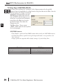
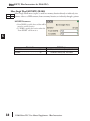
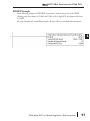
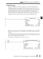
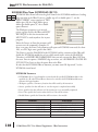
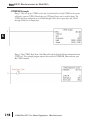
ANLGOUT Example
In the following example, the ANLGOUT instruction is used to setup the pointer method
for an analog output module that is installed in option slot 3. Two output channels are
enabled and the analog data will be read from V2100 - V2101 in BCD format.
1
2
3
4
S
6
7
8
9
10
11
12
13
14
A
B
C
D
No permissive contact or input logic is
used with this instruction
DL06 Micro PLC User Manual Supplement - IBox Instructions
11
DirectSOFT5 IBox Instructions for DL06 PLCs
Analog Scale 12 Bit BCD to BCD (ANSCL) (IB-423)
1
2
3
4
S
6
7
8
9
10
11
12
13
14
A
B
C
D
DS5
HPP
Analog Scale 12 Bit BCD to BCD scales a 12 bit BCD analog value (0-4095 BCD) into
N/A BCD engineering units. You specify the engineering unit high value (when raw is 4095), and
the engineering low value (when raw is
0), and the output V memory address
you want the to place the scaled
engineering unit value. The engineering
units are generated as BCD and can be
the full range of 0 to 9999 (see ANSCLB
- Analog Scale 12 Bit Binary to Binary if
your raw units are in Binary format).
Note that this IBox only works with
unipolar unsigned raw values. It does
NOT work with bipolar or sign plus
magnitude raw values.
Used
ANSCL Parameters
• Raw (0-4095 BCD): specifies the V-memory location of the unipolar unsigned raw 0-4095
unscaled value
• High Engineering: specifies the high engineering value when the raw input is 4095
• Low Engineering: specifies the low engineering value when the raw input is 0
• Engineering (BCD): specifies the V-memory location where the scaled engineering BCD value will
be placed
Parameter
Raw (0-4095 BCD) . . . . . . . . . . . . . . . . . . . . . V,P
High Engineering . . . . . . . . . . . . . . . . . . . . . . . . K
Low Engineering . . . . . . . . . . . . . . . . . . . . . . . . K
Engineering (BCD) . . . . . . . . . . . . . . . . . . . . . V,P
12
DL06 Range
See DL06 V-memory map - Data Words
K0-9999
K0-9999
See DL06 V-memory map - Data Words
DL06 Micro PLC User Manual Supplement - IBox Instructions
DirectSOFT5 IBox Instructions for DL06 PLCs
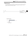
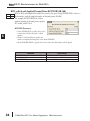
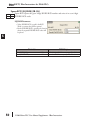
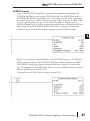
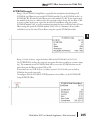
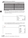
ANSCL Example
In the following example, the ANSCL instruction is used to scale a raw value (0-4095 BCD)
that is in V2000. The engineering scaling range is set 0-100 (low engineering value - high
engineering value). The scaled value will be placed in V2100 in BCD format.
SP1
DL06 Micro PLC User Manual Supplement - IBox Instructions
13
1
2
3
4
S
6
7
8
9
10
11
12
13
14
A
B
C
D
DirectSOFT5 IBox Instructions for DL06 PLCs
Analog Scale 12 Bit Binary to Binary (ANSCLB) (IB-403)
1
2
3
4
S
6
7
8
9
10
11
12
13
14
A
B
C
D
DS5
Used
HPP
N/A
Analog Scale 12 Bit Binary to Binary scales a 12 bit binary analog value (0-4095 decimal)
into binary (decimal) engineering units. You specify the engineering unit high value (when
raw is 4095), and the engineering low
value (when raw is 0), and the output V
memory address you want to place the
scaled engineering unit value. The
engineering units are generated as binary
and can be the full range of 0 to 65535
(see ANSCL - Analog Scale 12 Bit BCD
to BCD if your raw units are in BCD
format).
Note that this IBox only works with
unipolar unsigned raw values. It does
NOT work with bipolar, sign plus
magnitude, or signed 2's complement raw values.
ANSCLB Parameters
• Raw (12 bit binary): specifies the V-memory location of the unipolar unsigned raw decimal
unscaled value (12 bit binary = 0-4095 decimal)
• High Engineering: specifies the high engineering value when the raw input is 4095 decimal
• Low Engineering: specifies the low engineering value when the raw input is 0 decimal
• Engineering (binary): specifies the V-memory location where the scaled engineering decimal value
will be placed
Parameter
Raw (12 bit binary) . . . . . . . . . . . . . . . . . . . . V,P
High Engineering . . . . . . . . . . . . . . . . . . . . . . . . K
Low Engineering . . . . . . . . . . . . . . . . . . . . . . . . K
Engineering (binary) . . . . . . . . . . . . . . . . . . . . V,P
14
DL06 Range
See DL06 V-memory map - Data Words
K0-65535
K0-65535
See DL06 V-memory map - Data Words
DL06 Micro PLC User Manual Supplement - IBox Instructions
DirectSOFT5 IBox Instructions for DL06 PLCs
ANSCLB Example
In the following example, the ANSCLB instruction is used to scale a raw value (0-4095
binary) that is in V2000. The engineering scaling range is set 0-1000 (low engineering value high engineering value). The scaled value will be placed in V2100 in binary format.
SP1
DL06 Micro PLC User Manual Supplement - IBox Instructions
15
1
2
3
4
S
6
7
8
9
10
11
12
13
14
A
B
C
D
DirectSOFT5 IBox Instructions for DL06 PLCs
Filter Over Time - BCD (FILTER) (IB-422)
1
2
3
4
S
6
7
8
9
10
11
12
13
14
A
B
C
D
DS5
HPP
Filter Over Time BCD will perform a first-order filter on the Raw Data on a defined time
N/A interval. The equation is:
New = Old + [(Raw - Old) / FDC]
where,
New: New Filtered Value
Old: Old Filtered Value
FDC: Filter Divisor Constant
Raw: Raw Data
The Filter Divisor Constant is an integer in
the range K1 to K100, such that if it
equaled K1 then no filtering would be
done.
The rate at which the calculation is performed is specified by time in hundredths of a second
(0.01 seconds) as the Filter Freq Time parameter. Note that this Timer instruction is
embedded in the IBox and must NOT be used anywhere else in your program. Power flow
controls whether the calculation is enabled. If it is disabled, the Filter Value is not updated.
On the first scan from Program to Run mode, the Filter Value is initialized to 0 to give the
calculation a consistent starting point.
Used
FILTER Parameters
• Filter Frequency Timer: specifies the Timer (T) number which is used by the Filter instruction
• Filter Frequency Time (0.01sec): specifies the rate at which the calculation is performed
• Raw Data (BCD): specifies the V-memory location of the raw unfiltered BCD value
• Filter Divisor (1-100): this constant used to control the filtering effect. A larger value will increase
the smoothing effect of the filter. A value of 1 results with no filtering.
• Filtered Value (BCD): specifies the V-memory location where the filtered BCD value will be placed
Parameter
Filter Frequency Timer . . . . . . . . . . . . . . . . . . . T
Filter Frequency Time (0.01 sec) . . . . . . . . . . . K
Raw Data (BCD) . . . . . . . . . . . . . . . . . . . . . . . . V
Filter Divisor (1-100) . . . . . . . . . . . . . . . . . . . . . K
Filtered Value (BCD) . . . . . . . . . . . . . . . . . . . . . V
16
DL06 Range
T0-377
K0-9999
See DL06 V-memory map - Data Words
K1-100
See DL06 V-memory map - Data Words
DL06 Micro PLC User Manual Supplement - IBox Instructions
DirectSOFT5 IBox Instructions for DL06 PLCs
FILTER Example
In the following example, the Filter instruction is used to filter a BCD value that is in V2000.
Timer(T0) is set to 0.5 sec, the rate at which the filter calculation will be performed. The
filter constant is set to 2. A larger value will increase the smoothing effect of the filter. A value
of 1 results with no filtering. The filtered value will be placed in V2100.
SP1
DL06 Micro PLC User Manual Supplement - IBox Instructions
17
1
2
3
4
S
6
7
8
9
10
11
12
13
14
A
B
C
D
DirectSOFT5 IBox Instructions for DL06 PLCs
Filter Over Time - Binary (FILTERB) (IB-402)
1
2
3
4
S
6
7
8
9
10
11
12
13
14
A
B
C
D
DS5
Used
HPP
N/A
Filter Over Time in Binary (decimal) will perform a first-order filter on the Raw Data on a
defined time interval. The equation is
New = Old + [(Raw - Old) / FDC] where
New: New Filtered Value
Old: Old Filtered Value
FDC: Filter Divisor Constant
Raw: Raw Data
The Filter Divisor Constant is an integer in the
range K1 to K100, such that if it equaled K1
then no filtering would be done.
The rate at which the calculation is performed is specified by time in hundredths of a second
(0.01 seconds) as the Filter Freq Time parameter. Note that this Timer instruction is
embedded in the IBox and must NOT be used anywhere else in your program. Power flow
controls whether the calculation is enabled. If it is disabled, the Filter Value is not updated.
On the first scan from Program to Run mode, the Filter Value is initialized to 0 to give the
calculation a consistent starting point.
FILTERB Parameters
• Filter Frequency Timer: specifies the Timer (T) number which is used by the Filter instruction
• Filter Frequency Time (0.01sec): specifies the rate at which the calculation is performed
• Raw Data (Binary): specifies the V-memory location of the raw unfiltered binary (decimal) value
• Filter Divisor (1-100): this constant used to control the filtering effect. A larger value will increase
the smoothing effect of the filter. A value of 1 results with no filtering.
• Filtered Value (Binary): specifies the V-memory location where the filtered binary (decimal) value
will be placed
Parameter
Filter Frequency Timer . . . . . . . . . . . . . . . . . . . T
Filter Frequency Time (0.01 sec) . . . . . . . . . . . K
Raw Data (Binary) . . . . . . . . . . . . . . . . . . . . . . . V
Filter Divisor (1-100) . . . . . . . . . . . . . . . . . . . . . K
Filtered Value (Binary) . . . . . . . . . . . . . . . . . . . . V
18
DL06 Range
T0-377
K0-9999
See DL06 V-memory map - Data Words
K1-100
See DL06 V-memory map - Data Words
DL06 Micro PLC User Manual Supplement - IBox Instructions
DirectSOFT5 IBox Instructions for DL06 PLCs
FILTERB Example
In the following example, the FILTERB instruction is used to filter a binary value that is in
V2000. Timer(T1) is set to 0.5 sec, the rate at which the filter calculation will be performed.
The filter constant is set to 3. A larger value will increase the smoothing effect of the filter. A
value of 1 results with no filtering. The filtered value will be placed in V2100
SP1
DL06 Micro PLC User Manual Supplement - IBox Instructions
19
1
2
3
4
S
6
7
8
9
10
11
12
13
14
A
B
C
D
DirectSOFT5 IBox Instructions for DL06 PLCs
Hi/Low Alarm - BCD (HILOAL) (IB-421)
1
2
3
4
S
6
7
8
9
10
11
12
13
14
A
B
C
D
DS5
HPP
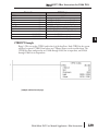
Hi/Low Alarm - BCD monitors a BCD value V memory location and sets four possible alarm
N/A states, High-High, High, Low, and Low-Low whenever the IBox has power flow. You enter
the alarm thresholds as constant K BCD values (K0-K9999) and/or BCD value V memory
locations.
Used
You must ensure that threshold limits are valid,
that is HH >= H > L >= LL. Note that when
the High-High or Low-Low alarm condition is
true, that the High and Low alarms will also be
set, respectively. This means you may use the
same threshold limit and same alarm bit for the
High-High and the High alarms in case you
only need one "High" alarm. Also note that the
boundary conditions are inclusive. That is, if
the Low boundary is K50, and the Low-Low
boundary is K10, and if the Monitoring Value equals 10, then the Low Alarm AND the LowLow alarm will both be ON. If there is no power flow to the IBox, then all alarm bits will be
turned off regardless of the value of the Monitoring Value parameter.
HILOAL Parameters
• Monitoring Value (BCD): specifies the V-memory location of the BCD value to be monitored
• High-High Limit: V-memory location or constant specifies the high-high alarm limit
• High-High Alarm: On when the high-high limit is reached
• High Limit: V-memory location or constant specifies the high alarm limit
• High Alarm: On when the high limit is reached
• Low Limit: V-memory location or constant specifies the low alarm limit
• Low Alarm: On when the low limit is reached
• Low-Low Limit: V-memory location or constant specifies the low-low alarm limit
• Low-Low Alarm: On when the low-low limit is reached
Parameter
Monitoring Value (BCD) . . . . . . . . . . . . . . . . . . V
High-High Limit . . . . . . . . . . . . . . . . . . . . . . . V, K
High-High Alarm . . . . . . . . . . . X, Y, C, GX,GY, B
High Limit . . . . . . . . . . . . . . . . . . . . . . . . . . . V, K
High Alarm. . . . . . . . . . . . . . . . X, Y, C, GX,GY, B
Low Limit . . . . . . . . . . . . . . . . . . . . . . . . . . . V, K
Low Alarm . . . . . . . . . . . . . . . . X, Y, C, GX,GY,B
Low-Low Limit . . . . . . . . . . . . . . . . . . . . . . . V, K
Low-Low Alarm . . . . . . . . . . . . X, Y, C, GX,GY, B
20
DL06 Range
See DL06 V-memory map - Data Words
K0-9999; or see DL06 V-memory map - Data Words
See DL06 V-memory map
K0-9999; or see DL06 V-memory map - Data Words
See DL06 V-memory map
K0-9999; or see DL06 V-memory map - Data Words
See DL06 V-memory map
K0-9999; or see DL06 V-memory map - Data Words
See DL06 V-memory map
DL06 Micro PLC User Manual Supplement - IBox Instructions
DirectSOFT5 IBox Instructions for DL06 PLCs
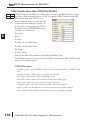
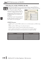
HILOAL Example
In the following example, the HILOAL instruction is used to monitor a BCD value that is in
V2000. If the value in V2000 meets/exceeds the high limit of K900, C101 will turn on. If the
value continues to increase to meet/exceed the high-high limit, C100 will turn on. Both bits
would be on in this case. The high and high-high limits and alarms can be set to the same
value if one “high” limit or alarm is desired to be used.
If the value in V2000 meets or falls below the low limit of K200, C102 will turn on. If the
value continues to decrease to meet or fall below the low-low limit of K100, C103 will turn
on. Both bits would be on in this case. The low and low-low limits and alarms can be set to
the same value if one “low” limit or alarm is desired to be used.
SP1
DL06 Micro PLC User Manual Supplement - IBox Instructions
21
1
2
3
4
S
6
7
8
9
10
11
12
13
14
A
B
C
D
DirectSOFT5 IBox Instructions for DL06 PLCs
Hi/Low Alarm - Binary (HILOALB) (IB-401)
1
2
3
4
S
6
7
8
9
10
11
12
13
14
A
B
C
D
DS5
HPP
Hi/Low Alarm - Binary monitors a binary (decimal) V memory location and sets four
N/A possible alarm states, High-High, High, Low, and Low-Low whenever the IBox has power
flow. You enter the alarm thresholds as constant K decimal values (K0-K65535) and/or binary
(decimal) V memory locations.
Used
You must ensure that threshold limits are valid,
that is HH >= H > L >= LL. Note that when
the High-High or Low-Low alarm condition is
true, that the High and Low alarms will also be
set, respectively. This means you may use the
same threshold limit and same alarm bit for the
High-High and the High alarms in case you
only need one "High" alarm. Also note that the
boundary conditions are inclusive. That is, if
the Low boundary is K50, and the Low-Low
boundary is K10, and if the Monitoring Value
equals 10, then the Low Alarm AND the Low-Low alarm will both be ON. If there is no
power flow to the IBox, then all alarm bits will be turned off regardless of the value of the
Monitoring Value parameter.
HILOALB Parameters
• Monitoring Value (Binary): specifies the V-memory location of the Binary value to be monitored
• High-High Limit: V-memory location or constant specifies the high-high alarm limit
• High-High Alarm: On when the high-high limit is reached
• High Limit: V-memory location or constant specifies the high alarm limit
• High Alarm: On when the high limit is reached
• Low Limit: V-memory location or constant specifies the low alarm limit
• Low Alarm: On when the low limit is reached
• Low-Low Limit: V-memory location or constant specifies the low-low alarm limit
• Low-Low Alarm: On when the low-low limit is reached
Parameter
Monitoring Value (Binary) . . . . . . . . . . . . . . . . V
High-High Limit . . . . . . . . . . . . . . . . . . . . . . . V, K
High-High Alarm . . . . . . . . . . . X, Y, C, GX,GY, B
High Limit . . . . . . . . . . . . . . . . . . . . . . . . . . . V, K
High Alarm. . . . . . . . . . . . . . . . X, Y, C, GX,GY, B
Low Limit . . . . . . . . . . . . . . . . . . . . . . . . . . . V, K
Low Alarm . . . . . . . . . . . . . . . . X, Y, C, GX,GY,B
Low-Low Limit . . . . . . . . . . . . . . . . . . . . . . . V, K
Low-Low Alarm . . . . . . . . . . . . X, Y, C, GX,GY, B
22
DL06 Range
See DL06 V-memory map - Data Words
K0-65535; or see DL06 V-memory map - Data Words
See DL06 V-memory map
K0-65535; or see DL06 V-memory map - Data Words
See DL06 V-memory map
K0-65535; or see DL06 V-memory map - Data Words
See DL06 V-memory map
K0-65535; or see DL06 V-memory map - Data Words
See DL06 V-memory map
DL06 Micro PLC User Manual Supplement - IBox Instructions
DirectSOFT5 IBox Instructions for DL06 PLCs
HILOALB Example
In the following example, the HILOALB instruction is used to monitor a binary value that is
in V2000. If the value in V2000 meets/exceeds the high limit of the binary value in V2011,
C101 will turn on. If the value continues to increase to meet/exceed the high-high limit value
in V2010, C100 will turn on. Both bits would be on in this case. The high and high-high
limits and alarms can be set to the same V-memory location/value if one “high” limit or alarm
is desired to be used.
If the value in V2000 meets or falls below the low limit of the binary value in V2012, C102
will turn on. If the value continues to decrease to meet or fall below the low-low limit in
V2013, C103 will turn on. Both bits would be on in this case. The low and low-low limits
and alarms can be set to the same V-memory location/value if one “low” limit or alarm is
desired to be used.
DL06 Micro PLC User Manual Supplement - IBox Instructions
23
1
2
3
4
S
6
7
8
9
10
11
12
13
14
A
B
C
D
DirectSOFT5 IBox Instructions for DL06 PLCs
Off Delay Timer (OFFDTMR) (IB-302)
1
2
3
4
S
6
7
8
9
10
11
12
13
14
A
B
C
D
DS5
HPP
Off Delay Timer will delay the "turning off" of the Output parameter by the specified Off
N/A Delay Time (in hundredths of a second) based on the power flow into the IBox. Once the
IBox receives power, the Output bit will turn
on immediately. When the power flow to the
IBox turns off, the Output bit WILL
REMAIN ON for the specified amount of
time (in hundredths of a second). Once the
Off Delay Time has expired, the output will
turn Off. If the power flow to the IBox comes
back on BEFORE the Off Delay Time, then
the timer is RESET and the Output will
remain On - so you must continuously have
NO power flow to the IBox for AT LEAST
the specified Off Delay Time before the Output will turn Off.
This IBox utilizes a Timer resource (TMRF), which cannot be used anywhere else in your
program.
Used
OFFDTMR Parameters
• Timer Number: specifies the Timer(TMRF) number which is used by the OFFDTMR instruction
• Off Delay Time (0.01sec): specifies how long the Output will remain on once power flow to the
Ibox is removed
• Output: specifies the output that will be delayed “turning off ” by the Off Delay Time.
Parameter
Timer Number . . . . . . . . . . . . . . . . . . . . . . . . . T
Off Delay Time . . . . . . . . . . . . . . . . . . . . . . . . K,V
Output . . . . . . . . . . . . . . . . . . . . X, Y, C, GX,GY, B
24
DL06 Range
T0-377
K0-9999; See DL06 V-memory map - Data Words
See DL06 V-memory map
DL06 Micro PLC User Manual Supplement - IBox Instructions
DirectSOFT5 IBox Instructions for DL06 PLCs
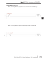
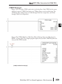
OFFDTMR Example
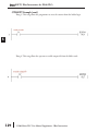
In the following example, the OFFDTMR instruction is used to delay the “turning off ”of
output C20. Timer 2 (T2) is set to 5 seconds, the “off-delay” period.
When C100 turns on, C20 turns on and will remain on while C100 is on. When C100 turns
off, C20 will remain for the specified Off Delay Time (5s), and then turn off.
Example timing diagram
C100
5 sec
5 sec
C20
DL06 Micro PLC User Manual Supplement - IBox Instructions
25
1
2
3
4
S
6
7
8
9
10
11
12
13
14
A
B
C
D
DirectSOFT5 IBox Instructions for DL06 PLCs
On Delay Timer (ONDTMR) (IB-301)
1
2
3
4
S
6
7
8
9
10
11
12
13
14
A
B
C
D
DS5
HPP
On Delay Timer will delay the "turning on" of the Output parameter by the specified
N/A amount of time (in hundredths of a second) based on the power flow into the IBox. Once the
IBox loses power, the Output is turned off
immediately. If the power flow turns off
BEFORE the On Delay Time, then the
timer is RESET and the Output is never
turned on, so you must have continuous
power flow to the IBox for at least the
specified On Delay Time before the
Output turns On.
This IBox utilizes a Timer resource
(TMRF), which cannot be used anywhere
else in your program.
Used
ONDTMR Parameters
• Timer Number: specifies the Timer(TMRF) number which is used by the ONDTMR instruction
• On Delay Time (0.01sec): specifies how long the Output will remain on once power flow to the
Ibox is removed
• Output: specifies the output that will be delayed “turning on” by the On Delay Time.
Parameter
Timer Number . . . . . . . . . . . . . . . . . . . . . . . . . T
On Delay Time . . . . . . . . . . . . . . . . . . . . . . . . K,V
Output . . . . . . . . . . . . . . . . . . . . X, Y, C, GX,GY, B
26
DL06 Range
T0-377
K0-9999; See DL06 V-memory map - Data Words
See DL06 V-memory map
DL06 Micro PLC User Manual Supplement - IBox Instructions
DirectSOFT5 IBox Instructions for DL06 PLCs
ONDTMR Example
In the following example, the ONDTMR instruction is used to delay the “turning on” of
output C21. Timer 1 (T1) is set to 2 seconds, the “on-delay” period.
When C101 turns on, C21 is delayed turning on by 2 seconds. When C101 turns off, C21
turns off immediately.
1
2
3
4
S
6
7
8
9
10
11
12
13
14
A
B
C
D
Example timing diagram
C101
2 sec
2 sec
C21
DL06 Micro PLC User Manual Supplement - IBox Instructions
27
DirectSOFT5 IBox Instructions for DL06 PLCs
One Shot (ONESHOT) (IB-303)
1
2
3
4
S
6
7
8
9
10
11
12
13
14
A
B
C
D
DS5
HPP
One Shot will turn on the given bit output parameter for one scan on an OFF to ON
N/A transition of the power flow into the IBox. This IBox is simply a different name for the PD
Coil (Positive Differential).
Used
ONESHOT Parameters
• Discrete Output: specifies the output that
will be on for one scan
Parameter
Discrete Output . . . . . . . . . . . . . . . . . . . . . X, Y, C
28
DL06 Range
See DL06 V-memory map
DL06 Micro PLC User Manual Supplement - IBox Instructions
DirectSOFT5 IBox Instructions for DL06 PLCs
ONESHOT Example
In the following example, the ONESHOT instruction is used to turn C100 on for one PLC
scan after C0 goes from an off to on transition. The input logic must produce an off to on
transition to execute the One Shot instruction.
Example timing diagram
C0
Scan time
C100
DL06 Micro PLC User Manual Supplement - IBox Instructions
29
1
2
3
4
S
6
7
8
9
10
11
12
13
14
A
B
C
D
DirectSOFT5 IBox Instructions for DL06 PLCs
Push On / Push Off Circuit (PONOFF) (IB-300)
1
2
3
4
S
6
7
8
9
10
11
12
13
14
A
B
C
D
DS5
Used
HPP
N/A
Push On/Push Off Circuit toggles an output state whenever its input power flow transitions
from off to on. Requires an extra bit parameter for scan-to-scan state information. This extra
bit must NOT be used anywhere else in the program. This is also known as a “flip-flop
circuit”.
PONOFF Parameters
• Discrete Input: specifies the input that will
toggle the specified output
• Discrete Output: specifies the output that
will be “turned on/off ” or toggled
• Internal State: specifies a work bit that is
used by the instruction
Parameter
Discrete Input . . . . X,Y,C,S,T,CT,GX,GY,SP,B,PB
Discrete Output . . . . . . . . . . . . . . X,Y,C,GX,GY,B
Internal State . . . . . . . . . . . . . . . . . . . . . . . X, Y, C
30
DL06 Range
See DL06 V-memory map
See DL06 V-memory map
See DL06 V-memory map
DL06 Micro PLC User Manual Supplement - IBox Instructions
DirectSOFT5 IBox Instructions for DL06 PLCs
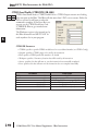
PONOFF Example
In the following example, the PONOFF instruction is used to control the on and off states of
the output C20 with a single input C10. When C10 is pressed once, C20 turns on. When
C10 is pressed again, C20 turns off. C100 is an internal bit used by the instruction.
DL06 Micro PLC User Manual Supplement - IBox Instructions
31
1
2
3
4
S
6
7
8
9
10
11
12
13
14
A
B
C
D
DirectSOFT5 IBox Instructions for DL06 PLCs
Move Single Word (MOVEW) (IB-200)
1
2
3
4
S
6
7
8
9
10
11
12
13
14
A
B
C
D
DS5
Used
HPP
N/A
Move Single Word moves (copies) a word to a memory location directly or indirectly via a
pointer, either as a HEX constant, from a memory location, or indirectly through a pointer
MOVEW Parameters
• From WORD: specifies the word that will be
moved to another location
• To WORD: specifies the location where the
“From WORD” will be move to
Parameter
From WORD . . . . . . . . . . . . . . . . . . . . . . . . V,P,K
To WORD. . . . . . . . . . . . . . . . . . . . . . . . . . . . . V,P
32
DL06 Range
K0-FFFF; See DL06 V-memory map - Data Words
See DL06 V-memory map - Data Words
DL06 Micro PLC User Manual Supplement - IBox Instructions
DirectSOFT5 IBox Instructions for DL06 PLCs
MOVEW Example
In the following example, the MOVEW instruction is used to move 16-bits of data from
V2000 to V3000 when C100 turns on.
DL06 Micro PLC User Manual Supplement - IBox Instructions
1
2
3
4
S
6
7
8
9
10
11
12
13
14
A
B
C
D
33
DirectSOFT5 IBox Instructions for DL06 PLCs
Move Double Word (MOVED) (IB-201)
1
2
3
4
S
6
7
8
9
10
11
12
13
14
A
B
C
D
DS5
Used
HPP
N/A
Move Double Word moves (copies) a double word to two consecutive memory locations
directly or indirectly via a pointer, either as a double HEX constant, from a double memory
location, or indirectly through a pointer to a
double memory location.
MOVED Parameters
• From DWORD: specifies the double word
that will be moved to another location
• To DWORD: specifies the location where the
“From DWORD” will be move to
Parameter
From DWORD . . . . . . . . . . . . . . . . . . . . . . V,P,K
To DWORD . . . . . . . . . . . . . . . . . . . . . . . . . . . V,P
34
DL06 Range
K0-FFFFFFFF; See DL06 V-memory map - Data Words
See DL06 V-memory map - Data Words
DL06 Micro PLC User Manual Supplement - IBox Instructions
DirectSOFT5 IBox Instructions for DL06 PLCs
MOVED Example
In the following example, the MOVED instruction is used to move 32-bits of data from
V2000 and V2001 to V3000 and V3001 when C100 turns on.
DL06 Micro PLC User Manual Supplement - IBox Instructions
1
2
3
4
S
6
7
8
9
10
11
12
13
14
A
B
C
D
35
DirectSOFT5 IBox Instructions for DL06 PLCs
BCD to Real with Implied Decimal Point (BCDTOR) (IB-560)
1
2
3
4
S
6
7
8
9
10
11
12
13
14
A
B
C
D
DS5
HPP
BCD to Real with Implied Decimal Point converts the given 4 digit WORD BCD value to a
N/A Real number, with the implied number of decimal points (K0-K4).
For example, BCDTOR K1234 with an
implied number of decimal points equal to
K1, would yield R123.4
Used
BCDTOR Parameters
• Value (WORD BCD): specifies the word or
constant that will be converted to a Real
number
• Number of Decimal Points: specifies the
number of implied decimal points in the Result DWORD
• Result (DWORD REAL): specifies the location where the Real number will be placed
Parameter
Value (WORD BCD) . . . . . . . . . . . . . . . . . . V,P,K
Number of Decimal Points . . . . . . . . . . . . . . . K
Result (DWORD REAL) . . . . . . . . . . . . . . . . . . . V
36
DL06 Range
K0-9999; See DL06 V-memory map - Data Words
K0-4
See DL06 V-memory map - Data Words
DL06 Micro PLC User Manual Supplement - IBox Instructions
DirectSOFT5 IBox Instructions for DL06 PLCs
BCDTOR Example
In the following example, the BCDTOR instruction is used to convert the 16-bit data in
V2000 from a 4-digit BCD data format to a 32-bit REAL (floating point) data format and
stored into V3000 and V3001.
K2 in the Number of Decimal Points implies the data will have two digits to the right of the
decimal point.
DL06 Micro PLC User Manual Supplement - IBox Instructions
37
1
2
3
4
S
6
7
8
9
10
11
12
13
14
A
B
C
D
DirectSOFT5 IBox Instructions for DL06 PLCs
Double BCD to Real with Implied Decimal Point (BCDTORD) (IB-562)
1
2
3
4
S
6
7
8
9
10
11
12
13
14
A
B
C
D
DS5
HPP
Double BCD to Real with Implied Decimal Point converts the given 8 digit DWORD BCD
N/A value to a Real number, given an implied
number of decimal points (K0-K8).
For example, BCDTORD K12345678 with
an implied number of decimal points equal to
K5, would yield R123.45678
Used
BCDTORD Parameters
• Value (DWORD BCD): specifies the Dword
or constant that will be converted to a Real
number
• Number of Decimal Points: specifies the number of implied decimal points in the Result DWORD
• Result (DWORD REAL): specifies the location where the Real number will be placed
Parameter
Value (DWORD BCD) . . . . . . . . . . . . . . . . . V,P,K
Number of Decimal Points . . . . . . . . . . . . . . . K
Result (DWORD REAL) . . . . . . . . . . . . . . . . . . . V
38
DL06 Range
K0-99999999; See DL06 V-memory map - Data Words
K0-8
See DL06 V-memory map - Data Words
DL06 Micro PLC User Manual Supplement - IBox Instructions
DirectSOFT5 IBox Instructions for DL06 PLCs
BCDTORD Example
In the following example, the BCDTORD instruction is used to convert the 32-bit data in
V2000 from an 8-digit BCD data format to a 32-bit REAL (floating point) data format and
stored into V3000 and V3001.
K2 in the Number of Decimal Points implies the data will have two digits to the right of the
decimal point.
DL06 Micro PLC User Manual Supplement - IBox Instructions
39
1
2
3
4
S
6
7
8
9
10
11
12
13
14
A
B
C
D
DirectSOFT5 IBox Instructions for DL06 PLCs
Math - BCD (MATHBCD) (IB-521)
1
2
3
4
S
6
7
8
9
10
11
12
13
14
A
B
C
D
DS5
HPP
Math - BCD Format lets you enter complex mathematical expressions like you would in
N/A Visual Basic, Excel, or C++ to do complex
calculations, nesting parentheses up to 4 levels
deep. In addition to + - * /, you can do
Modulo (% aka Remainder), Bit-wise And
(&) Or (|) Xor (^), and some BCD functions
- Convert to BCD (BCD), Convert to Binary
(BIN), BCD Complement (BCDCPL),
Convert from Gray Code (GRAY), Invert Bits
(INV), and BCD/HEX to Seven Segment
Display (SEG).
Example: ((V2000 + V2001) / (V2003 - K100)) * GRAY(V3000 & K001F)
Every V-memory reference MUST be to a single word BCD formatted value. Intermediate
results can go up to 32 bit values, but as long as the final result fits in a 16 bit BCD word, the
calculation is valid. Typical example of this is scaling using multiply then divide, (V2000 *
K1000) / K4095. The multiply term most likely will exceed 9999 but fits within 32 bits. The
divide operation will divide 4095 into the 32-bit accumulator, yielding a result that will
always fit in 16 bits.
You can reference binary V-memory values by using the BCD conversion function on a V
memory location but NOT an expression. That is BCD(V2000) is okay and will convert
V2000 from Binary to BCD, but BCD(V2000 + V3000) will add V2000 as BCD, to V3000
as BCD, then interpret the result as Binary and convert it to BCD - NOT GOOD.
Also, the final result is a 16 bit BCD number and so you could do BIN around the entire
operation to store the result as Binary.
Used
MATHBCD Parameters
• WORD Result: specifies the location where the BCD result of the mathematical expression will be
placed (result must fit into 16 bit single V-memory location)
• Expression: specifies the mathematical expression to be executed and the result is stored in specified
WORD Result. Each V-memory location used in the expression must be in BCD format.
Parameter
WORD Result . . . . . . . . . . . . . . . . . . . . . . . . . . V
Expression . . . . . . . . . . . . . . . . . . . . . . . . . . . . . .
40
DL06 Range
See DL06 V-memory map - Data Words
Text
DL06 Micro PLC User Manual Supplement - IBox Instructions
DirectSOFT5 IBox Instructions for DL06 PLCs
MATHBCD Example
In the following example, the MATHBCD instruction is used to calculate the math
expression which multiplies the BCD value in V1200 by 1000 then divides by 4095 and
loads the resulting value in V2000.
DL06 Micro PLC User Manual Supplement - IBox Instructions
1
2
3
4
S
6
7
8
9
10
11
12
13
14
A
B
C
D
41
DirectSOFT5 IBox Instructions for DL06 PLCs
Math - Binary (MATHBIN) (IB-501)
1
2
3
4
S
6
7
8
9
10
11
12
13
14
A
B
C
D
DS5
HPP
Math - Binary Format lets you enter complex mathematical expressions like you would in
N/A Visual Basic, Excel, or C++ to do complex calculations, nesting parentheses up to 4 levels
deep. In addition to + - * /, you can do
Modulo (% aka Remainder), Shift Right
(>>) and Shift Left (<<), Bit-wise And (&)
Or (|) Xor (^), and some binary functions Convert to BCD (BCD), Convert to Binary
(BIN), Decode Bits (DECO), Encode Bits
(ENCO), Invert Bits (INV), HEX to Seven
Segment Display (SEG), and Sum Bits
(SUM).
Example: ((V2000 + V2001) / (V2003 K10)) * SUM(V3000 & K001F)
Every V-memory reference MUST be to a single word binary formatted value. Intermediate
results can go up to 32 bit values, but as long as the final result fits in a 16 bit binary word,
the calculation is valid. Typical example of this is scaling using multiply then divide, (V2000 *
K1000) / K4095. The multiply term most likely will exceed 65535 but fits within 32 bits.
The divide operation will divide 4095 into the 32-bit accumulator, yielding a result that will
always fit in 16 bits.
You can reference BCD V memory values by using the BIN conversion function on a Vmemory location but NOT an expression. That is, BIN(V2000) is okay and will convert
V2000 from BCD to Binary, but BIN(V2000 + V3000) will add V2000 as Binary, to V3000
as Binary, then interpret the result as BCD and convert it to Binary - NOT GOOD.
Also, the final result is a 16 bit binary number and so you could do BCD around the entire
operation to store the result as BCD.
Used
MATHBIN Parameters
• WORD Result: specifies the location where the binary result of the mathematical expression will be
placed (result must fit into 16 bit single V-memory location)
• Expression: specifies the mathematical expression to be executed and the result is stored in specified
WORD Result. Each V-memory location used in the expression must be in binary format.
Parameter
WORD Result . . . . . . . . . . . . . . . . . . . . . . . . . . V
Expression . . . . . . . . . . . . . . . . . . . . . . . . . . . . . .
42
DL06 Range
See DL06 V-memory map - Data Words
Text
DL06 Micro PLC User Manual Supplement - IBox Instructions
DirectSOFT5 IBox Instructions for DL06 PLCs
MATHBIN Example
In the following example, the MATHBIN instruction is used to calculate the math expression
which multiplies the Binary value in V1200 by 1000 then divides by 4095 and loads the
resulting value in V2000.
DL06 Micro PLC User Manual Supplement - IBox Instructions
43
1
2
3
4
S
6
7
8
9
10
11
12
13
14
A
B
C
D
DirectSOFT5 IBox Instructions for DL06 PLCs
Math - Real (MATHR) (IB-541)
1
2
3
4
S
6
7
8
9
10
11
12
13
14
A
B
C
D
DS5
Used
HPP
N/A
Math - Real Format lets you enter complex mathematical expressions like you would in
Visual Basic, Excel, or C++ to do complex calculations, nesting parentheses up to 4 levels
deep. In addition to + - * /, you can do Bitwise And (&) Or (|) Xor (^), and many Real
functions - Arc Cosine (ACOSR), Arc Sine
(ASINR), Arc Tangent (ATANR), Cosine
(COSR), Convert Radians to Degrees
(DEGR), Invert Bits (INV), Convert Degrees
to Radians (RADR), HEX to Seven Segment
Display (SEG), Sine (SINR), Square Root
(SQRTR), Tangent (TANR).
Example: ((V2000 + V2002) / (V2004 R2.5)) * SINR(RADR(V3000 / R10.0))
Every V-memory reference MUST be able to fit into a double word Real formatted value.
MATHR Parameters
• DWORD Result: specifies the location where the Real result of the mathematical expression will be
placed (result must fit into a double word Real formatted location)
• Expression: specifies the mathematical expression to be executed and the result is stored in specified
DWORD Result location. Each V-memory location used in the expression must be in Real format.
Parameter
DWORD Result . . . . . . . . . . . . . . . . . . . . . . . . V
Expression . . . . . . . . . . . . . . . . . . . . . . . . . . . . . .
44
DL06 Range
See DL06 V-memory map - Data Words
Text
DL06 Micro PLC User Manual Supplement - IBox Instructions
DirectSOFT5 IBox Instructions for DL06 PLCs
MATHR Example
In the following example, the MATHR instruction is used to calculate the math expression
which multiplies the REAL (floating point) value in V1200 by 10.5 then divides by 2.7 and
loads the resulting 32-bit value in V2000 and V2001.
DL06 Micro PLC User Manual Supplement - IBox Instructions
45
1
2
3
4
S
6
7
8
9
10
11
12
13
14
A
B
C
D
DirectSOFT5 IBox Instructions for DL06 PLCs
Real to BCD with Implied Decimal Point and Rounding (RTOBCD) (IB-561)
1
2
3
4
S
6
7
8
9
10
11
12
13
14
A
B
C
D
DS5
HPP
Real to BCD with Implied Decimal Point and Rounding converts the absolute value of the
N/A given Real number to a 4 digit BCD number, compensating for an implied number of
decimal points (K0-K4) and performs
rounding.
For example, RTOBCD R56.74 with an
implied number of decimal points equal to
K1, would yield 567 BCD. If the implied
number of decimal points was 0, then the
function would yield 57 BCD (note that it
rounded up).
If the Real number is negative, the Result will
equal its positive, absolute value.
Used
RTOBCD Parameters
• Value (DWORD Real): specifies the Real Dword location or number that will be converted and
rounded to a BCD number with decimal points
• Number of Decimal Points: specifies the number of implied decimal points in the Result WORD
• Result (WORD BCD): specifies the location where the rounded/implied decimal points BCD value
will be placed
Parameter
Value (DWORD Real) . . . . . . . . . . . . . . . . . V,P,R
Number of Decimal Points . . . . . . . . . . . . . . . K
Result (WORD BCD) . . . . . . . . . . . . . . . . . . . . . V
46
DL06 Range
R ; See DL06 V-memory map - Data Words
K0-4
See DL06 V-memory map - Data Words
DL06 Micro PLC User Manual Supplement - IBox Instructions
DirectSOFT5 IBox Instructions for DL06 PLCs
RTOBCD Example
In the following example, the RTOBCD instruction is used to convert the 32-bit REAL
(floating point) data format in V3000 and V3001 to the 4-digit BCD data format and stored
in V2000.
K2 in the Number of Decimal Points implies the data will have two implied decimal points.
DL06 Micro PLC User Manual Supplement - IBox Instructions
47
1
2
3
4
S
6
7
8
9
10
11
12
13
14
A
B
C
D
DirectSOFT5 IBox Instructions for DL06 PLCs
1
2
3
4
S
6
7
8
9
10
11
12
13
14
A
B
C
D
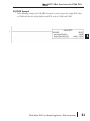
Real to Double BCD with Implied Decimal Point and Rounding (RTOBCDD)
(IB-563)
DS5
HPP
Real to Double BCD with Implied Decimal
N/A Point and Rounding converts the absolute
value of the given Real number to an 8 digit
DWORD BCD number, compensating for
an implied number of decimal points (K0K8) and performs rounding.
For example, RTOBCDD R38156.74 with
an implied number of decimal points equal
to K1, would yield 381567 BCD. If the
implied number of decimal points was 0,
then the function would yield 38157 BCD
(note that it rounded up).
If the Real number is negative, the Result will equal its positive, absolute value.
Used
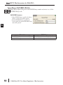
RTOBCDD Parameters
• Value (DWORD Real): specifies the Dword Real number that will be converted and rounded to a
BCD number with decimal points
• Number of Decimal Points: specifies the number of implied decimal points in the Result DWORD
• Result (DWORD BCD): specifies the location where the rounded/implied decimal points
DWORD BCD value will be placed
Parameter
Value (DWORD Real) . . . . . . . . . . . . . . . . . V,P,R
Number of Decimal Points . . . . . . . . . . . . . . . K
Result (DWORD BCD) . . . . . . . . . . . . . . . . . . . . V
48
DL06 Range
R ; See DL06 V-memory map - Data Words
K0-8
See DL06 V-memory map - Data Words
DL06 Micro PLC User Manual Supplement - IBox Instructions
DirectSOFT5 IBox Instructions for DL06 PLCs
RTOBCDD Example
In the following example, the RTOBCDD instruction is used to convert the 32-bit REAL
(floating point) data format in V3000 and V3001 to the 8-digit BCD data format and stored
in V2000 and V2001.
K2 in the Number of Decimal Points implies the data will have two implied decimal points.
DL06 Micro PLC User Manual Supplement - IBox Instructions
49
1
2
3
4
S
6
7
8
9
10
11
12
13
14
A
B
C
D
DirectSOFT5 IBox Instructions for DL06 PLCs
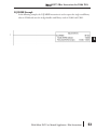
Square BCD (SQUARE) (IB-523)
1
2
3
4
S
6
7
8
9
10
11
12
13
14
A
B
C
D
DS5
HPP
Square BCD squares the given 4-digit WORD BCD number and writes it in as an 8-digit
N/A DWORD BCD result.
Used
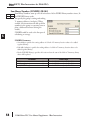
SQUARE Parameters
• Value (WORD BCD): specifies the BCD
Word or constant that will be squared
• Result (DWORD BCD): specifies the location
where the squared DWORD BCD value will
be placed
Parameter
Value (WORD BCD) . . . . . . . . . . . . . . . . . . V,P,K
Result (DWORD BCD) . . . . . . . . . . . . . . . . . . . . V
50
DL06 Range
K0-9999 ; See DL06 V-memory map - Data Words
See DL06 V-memory map - Data Words
DL06 Micro PLC User Manual Supplement - IBox Instructions
DirectSOFT5 IBox Instructions for DL06 PLCs
SQUARE Example
In the following example, the SQUARE instruction is used to square the 4-digit BCD value
in V2000 and store the 8-digit double word BCD result in V3000 and V3001
DL06 Micro PLC User Manual Supplement - IBox Instructions
51
1
2
3
4
S
6
7
8
9
10
11
12
13
14
A
B
C
D
DirectSOFT5 IBox Instructions for DL06 PLCs
Square Binary (SQUAREB) (IB-503)
1
2
3
4
S
6
7
8
9
10
11
12
13
14
A
B
C
D
DS5
HPP
Square Binary squares the given 16-bit WORD Binary number and writes it as a 32-bit
N/A DWORD Binary result.
Used
SQUAREB Parameters
• Value (WORD Binary): specifies the binary
Word or constant that will be squared
• Result (DWORD Binary): specifies the
location where the squared DWORD binary
value will be placed
Parameter
Value (WORD Binary) . . . . . . . . . . . . . . . . V,P,K
Result (DWORD Binary) . . . . . . . . . . . . . . . . . . V
52
DL06 Range
K0-65535; See DL06 V-memory map - Data Words
See DL06 V-memory map - Data Words
DL06 Micro PLC User Manual Supplement - IBox Instructions
DirectSOFT5 IBox Instructions for DL06 PLCs
SQUAREB Example
In the following example, the SQUAREB instruction is used to square the single word Binary
value in V2000 and store the 8-digit double word Binary result in V3000 and V3001.
DL06 Micro PLC User Manual Supplement - IBox Instructions
53
1
2
3
4
S
6
7
8
9
10
11
12
13
14
A
B
C
D
DirectSOFT5 IBox Instructions for DL06 PLCs
Square Real (SQUARER) (IB-543)
1
2
3
4
S
6
7
8
9
10
11
12
13
14
A
B
C
D
DS5
Used
HPP
N/A
Square Real squares the given REAL DWORD number and writes it to a REAL DWORD
result.
SQUARER Parameters
• Value (REAL DWORD): specifies the Real
DWORD location or number that will be
squared
• Result (REAL DWORD): specifies the
location where the squared Real DWORD
value will be placed
Parameter
Value (REAL DWORD) . . . . . . . . . . . . . . . . V,P,R
Result (REAL DWORD) . . . . . . . . . . . . . . . . . . . V
54
DL06 Range
R ; See DL06 V-memory map - Data Words
See DL06 V-memory map - Data Words
DL06 Micro PLC User Manual Supplement - IBox Instructions
DirectSOFT5 IBox Instructions for DL06 PLCs
SQUARER Example
In the following example, the SQUARER instruction is used to square the 32-bit floating
point REAL value in V2000 and V2001 and store the REAL value result in V3000 and
V3001.
DL06 Micro PLC User Manual Supplement - IBox Instructions
1
2
3
4
S
6
7
8
9
10
11
12
13
14
A
B
C
D
55
DirectSOFT5 IBox Instructions for DL06 PLCs
Sum BCD Numbers (SUMBCD) (IB-522)
1
2
3
4
S
6
7
8
9
10
11
12
13
14
A
B
C
D
DS5
HPP
Sum BCD Numbers sums up a list of consecutive 4-digit WORD BCD numbers into an 8N/A digit DWORD BCD result.
You specify the group's starting and ending
V- memory addresses (inclusive). When
enabled, this instruction will add up all the
numbers in the group (so you may want to
place a differential contact driving the
enable).
SUMBCD could be used as the first part of
calculating an average.
Used
SUMBCD Parameters
• Start Address: specifies the starting address of a block of V-memory location values to be added
together (BCD)
• End Addr (inclusive): specifies the ending address of a block of V-memory location values to be
added together (BCD)
• Result (DWORD BCD): specifies the location where the sum of the block of V-memory BCD
values will be placed
Parameter
Start Address . . . . . . . . . . . . . . . . . . . . . . . . . . V
End Address (inclusive) . . . . . . . . . . . . . . . . . . V
Result (DWORD BCD) . . . . . . . . . . . . . . . . . . . . V
56
DL06 Range
See DL06 V-memory map - Data Words
See DL06 V-memory map - Data Words
See DL06 V-memory map - Data Words
DL06 Micro PLC User Manual Supplement - IBox Instructions
DirectSOFT5 IBox Instructions for DL06 PLCs
SUMBCD Example
In the following example, the SUMBCD instruction is used to total the sum of all BCD
values in words V2000 thru V2007 and store the resulting 8-digit double word BCD value in
V3000 and V3001.
DL06 Micro PLC User Manual Supplement - IBox Instructions
57
1
2
3
4
S
6
7
8
9
10
11
12
13
14
A
B
C
D
DirectSOFT5 IBox Instructions for DL06 PLCs
Sum Binary Numbers (SUMBIN) (IB-502)
1
2
3
4
S
6
7
8
9
10
11
12
13
14
A
B
C
D
DS5
HPP
Sum Binary Numbers sums up a list of consecutive 16-bit WORD Binary numbers into a 32N/A bit DWORD binary result.
You specify the group's starting and ending
V- memory addresses (inclusive). When
enabled, this instruction will add up all the
numbers in the group (so you may want to
place a differential contact driving the
enable).
SUMBIN could be used as the first part of
calculating an average.
Used
SUMBIN Parameters
• Start Address: specifies the starting address of a block of V-memory location values to be added
together (Binary)
• End Addr (inclusive): specifies the ending address of a block of V-memory location values to be
added together (Binary)
• Result (DWORD Binary): specifies the location where the sum of the block of V-memory binary
values will be placed
Parameter
Start Address . . . . . . . . . . . . . . . . . . . . . . . . . . V
End Address (inclusive) . . . . . . . . . . . . . . . . . . V
Result (DWORD Binary) . . . . . . . . . . . . . . . . . . V
58
DL06 Range
See DL06 V-memory map - Data Words
See DL06 V-memory map - Data Words
See DL06 V-memory map - Data Words
DL06 Micro PLC User Manual Supplement - IBox Instructions
DirectSOFT5 IBox Instructions for DL06 PLCs
SUMBIN Example
In the following example, the SUMBIN instruction is used to total the sum of all Binary
values in words V2000 thru V2007 and store the resulting 8-digit double word Binary value
in V3000 and V3001.
DL06 Micro PLC User Manual Supplement - IBox Instructions
59
1
2
3
4
S
6
7
8
9
10
11
12
13
14
A
B
C
D
DirectSOFT5 IBox Instructions for DL06 PLCs
Sum Real Numbers (SUMR) (IB-542)
1
2
3
4
S
6
7
8
9
10
11
12
13
14
A
B
C
D
DS5
HPP
Sum Real Numbers sums up a list of consecutive REAL DWORD numbers into a REAL
N/A DWORD result.
You specify the group's starting and ending
V- memory addresses (inclusive).
Remember that Real numbers are DWORDs
and occupy 2 words of V memory each, so
the number of Real values summed up is
equal to half the number of memory
locations. Note that the End Address can be
EITHER word of the 2 word ending address,
for example, if you wanted to add the 4 Real
numbers stored in V2000 thru V2007
(V2000, V2002, V2004, and V2006), you can specify V2006 OR V2007 for the ending
address and you will get the same result.
When enabled, this instruction will add up all the numbers in the group (so you may want to
place a differential contact driving the enable).
SUMR could be used as the first part of calculating an average.
Used
SUMR Parameters
• Start Address (DWORD): specifies the starting address of a block of V-memory location values to
be added together (Real)
• End Addr (inclusive) (DWORD): specifies the ending address of a block of V-memory location
values to be added together (Real)
• Result (DWORD): specifies the location where the sum of the block of V-memory Real values will
be placed
Parameter
Start Address (inclusive DWORD) . . . . . . . . . V
End Address (inclusive DWORD) . . . . . . . . . . V
Result (DWORD) . . . . . . . . . . . . . . . . . . . . . . . . V
60
DL06 Range
See DL06 V-memory map - Data Words
See DL06 V-memory map - Data Words
See DL06 V-memory map - Data Words
DL06 Micro PLC User Manual Supplement - IBox Instructions
DirectSOFT5 IBox Instructions for DL06 PLCs
SUMR Example
In the following example, the SUMR instruction is used to total the sum of all floating point
REAL number values in words V2000 thru V2007 and store the resulting 32-bit floating
point REAL number value in V3000 and V3001.
DL06 Micro PLC User Manual Supplement - IBox Instructions
61
1
2
3
4
S
6
7
8
9
10
11
12
13
14
A
B
C
D
DirectSOFT5 IBox Instructions for DL06 PLCs
ECOM100 Configuration (ECOM100) (IB-710)
1
2
3
4
S
6
7
8
9
10
11
12
13
14
A
B
C
D
DS5
Used
HPP
N/A
ECOM100 Configuration defines all the common information for one specific ECOM100
module which is used by the other ECOM100 IBoxes; for example, ECRX - ECOM100
Network Read , ECEMAIL - ECOM100
Send EMail, ECIPSUP - ECOM100 IP
Setup, etc.
You MUST have the ECOM100
Configuration IBox at the top of your
ladder/stage program with any other
configuration IBoxes. The Message Buffer
parameter specifies the starting address of a
65 WORD buffer. This is 101 Octal
addresses (e.g. V1400 thru V1500).
If you have more than one ECOM100 in
your PLC, you must have a different ECOM100 Configuration IBox for EACH ECOM100
module in your system that utilizes any ECOM IBox instructions.
The Workspace and Status parameters and the entire Message Buffer are internal, private
registers used by the ECOM100 Configuration IBox and MUST BE UNIQUE in this one
instruction and MUST NOT be used anywhere else in your program.
In order for MOST ECOM100 IBoxes to function, you must turn ON dip switch 7 on the
ECOM100 circuit board. You can keep dip switch 7 off if you are ONLY using ECOM100
Network Read and Write IBoxes (ECRX, ECWX).
ECOM100 Parameters
• ECOM100#: this is a logical number associated with this specific ECOM100 module in the
specified slot. All other ECxxxx IBoxes that need to reference this ECOM100 module must
reference this logical number
• Slot: specifies the option slot the module occupies
• Status: specifies a V-memory location that will be used by the instruction
• Workspace: specifies a V-memory location that will be used by the instruction
• Msg Buffer: specifies the starting address of a 65 word buffer that will be used by the module for
configuration
Parameter
ECOM100# . . . . . . . . . . . . . . . . . . . . . . . . . . . . K
Slot . . . . . . . . . . . . . . . . . . . . . . . . . . . . . . . . . . K
Status . . . . . . . . . . . . . . . . . . . . . . . . . . . . . . . . V
Workspace . . . . . . . . . . . . . . . . . . . . . . . . . . . . V
Msg Buffer (65 words used) . . . . . . . . . . . . . . . V
62
DL06 Range
K0-255
K1-4
See DL06 V-memory map - Data Words
See DL06 V-memory map - Data Words
See DL06 V-memory map - Data Words
DL06 Micro PLC User Manual Supplement - IBox Instructions
DirectSOFT5 IBox Instructions for DL06 PLCs
ECOM100 Example
The ECOM100 Config IBox coordinates all of the interaction with other ECOM100 based
IBoxes (ECxxxx). You must have an ECOM100 Config IBox for each ECOM100 module in
your system. Configuration IBoxes must be at the top of your program and must execute
every scan.
This IBox defines ECOM100# K0 to be in slot 3. Any ECOM100 IBoxes that need to
reference this specific module (such as ECEMAIL, ECRX, ...) would enter K0 for their
ECOM100# parameter.
The Status register is for reporting any completion or error information to other ECOM100
IBoxes. This V memory register must not be used anywhere else in the entire program.
The Workspace register is used to maintain state information about the ECOM100, along
with proper sharing and interlocking with the other ECOM100 IBoxes in the program. This
V memory register must not be used anywhere else in the entire program.
The Message Buffer of 65 words (130 bytes) is a common pool of memory that is used by
other ECOM100 IBoxes (such as ECEMAIL). This way, you can have a bunch of
ECEMAIL IBoxes, but only need 1 common buffer for generating and sending each EMail.
These V memory registers must not be used anywhere else in your entire program.
DL06 Micro PLC User Manual Supplement - IBox Instructions
63
1
2
3
4
S
6
7
8
9
10
11
12
13
14
A
B
C
D
DirectSOFT5 IBox Instructions for DL06 PLCs
ECOM100 Disable DHCP (ECDHCPD) (IB-736)
1
2
3
4
S
6
7
8
9
10
11
12
13
14
A
B
C
D
DS5
HPP
ECOM100 Disable DHCP will setup the ECOM100 to use its internal TCP/IP settings on a
N/A leading edge transition to the IBox. To configure the ECOM100's TCP/IP settings manually,
use the NetEdit3 utility, or you can do it
programmatically from your PLC program
using the ECOM100 IP Setup (ECIPSUP), or
the individual ECOM100 IBoxes: ECOM
Write IP Address (ECWRIP), ECOM Write
Gateway Address (ECWRGWA), and
ECOM100 Write Subnet Mask
(ECWRSNM).
The Workspace parameter is an internal,
private register used by this IBox and MUST
BE UNIQUE in this one instruction and
MUST NOT be used anywhere else in your program.
Either the Success or Error bit parameter will turn on once the command is complete. If there
is an error, the Error Code parameter will report an ECOM100 error code (less than 100), or
a PLC logic error (greater than 1000).
The "Disable DHCP" setting is stored in Flash-ROM in the ECOM100 and the execution of
this IBox will disable the ECOM100 module for at least a half second until it writes the
Flash-ROM. Therefore, it is HIGHLY RECOMMENDED that you only execute this IBox
ONCE, on first scan. Since it requires a LEADING edge to execute, use a NORMALLY
CLOSED SP0 (STR NOT First Scan) to drive the power flow to the IBox.
In order for this ECOM100 IBox to function, you must turn ON dip switch 7 on the
ECOM100 circuit board.
Used
ECDHCPD Parameters
• ECOM100#: this is a logical number associated with this specific ECOM100 module in the
specified slot. All other ECxxxx IBoxes that need to reference this ECOM100 module must
reference this logical number
• Workspace: specifies a V-memory location that will be used by the instruction
• Success: specifies a bit that will turn on once the request is completed successfully
• Error: specifies a bit that will turn on if the instruction is not successfully completed
• Error Code: specifies the location where the Error Code will be written
Parameter
ECOM100# . . . . . . . . . . . . . . . . . . . . . . . . . . . . K
Workspace . . . . . . . . . . . . . . . . . . . . . . . . . . . . V
Success . . . . . . . . . . . . . . . . . . . . X,Y,C,GX,GY,B
Error . . . . . . . . . . . . . . . . . . . . . . X,Y,C,GX,GY,B
Error Code . . . . . . . . . . . . . . . . . . . . . . . . . . . . . V
64
DL06 Range
K0-255
See DL06 V-memory map - Data Words
See DL06 V-memory map
See DL06 V-memory map
See DL06 V-memory map - Data Words
DL06 Micro PLC User Manual Supplement - IBox Instructions
DirectSOFT5 IBox Instructions for DL06 PLCs
ECDHCPD Example
Rung 1: The ECOM100 Config IBox is responsible for coordination/interlocking of all
ECOM100 type IBoxes for one specific ECOM100 module. Tag the ECOM100 in slot 1 as
ECOM100# K0. All other ECxxxx IBoxes refer to this module # as K0. If you need to move
the module in the base to a different slot, then you only need to change this one IBox. V400
is used as a global result status register for the other ECxxxx IBoxes using this specific
ECOM100 module. V401 is used to coordinate/interlock the logic in all of the other ECxxxx
IBoxes using this specific ECOM100 module. V402-V502 is a common 130 byte buffer
available for use by the other ECxxxx IBoxes using this specific ECOM100 module.
Rung 2: On the 2nd scan, disable DHCP in the ECOM100. DHCP is the same protocol
used by PCs for using a DHCP Server to automatically assign the ECOM100's IP Address,
Gateway Address, and Subnet Mask. Typically disabling DHCP is done by assigning a hardcoded IP Address either in NetEdit or using one of the ECOM100 IP Setup IBoxes, but this
IBox allows you to disable DHCP in the ECOM100 using your ladder program. The
ECDHCPD is leading edge triggered, not power-flow driven (similar to a counter input leg).
The command to disable DHCP will be sent to the ECOM100 whenever the power flow
into the IBox goes from OFF to ON. If successful, turn on C100. If there is a failure, turn on
C101. If it fails, you can look at V2000 for the specific error code.
DL06 Micro PLC User Manual Supplement - IBox Instructions
65
1
2
3
4
S
6
7
8
9
10
11
12
13
14
A
B
C
D
DirectSOFT5 IBox Instructions for DL06 PLCs
ECOM100 Enable DHCP (ECDHCPE) (IB-735)
1
2
3
4
S
6
7
8
9
10
11
12
13
14
A
B
C
D
DS5
Used
HPP
N/A
ECOM100 Enable DHCP will tell the ECOM100 to obtain its TCP/IP setup from a DHCP
Server on a leading edge transition to the IBox.
The IBox will be successful once the
ECOM100 has received its TCP/IP settings
from the DHCP server. Since it is possible for
the DHCP server to be unavailable, a
Timeout parameter is provided so that the
IBox can complete, but with an Error (Error
Code = 1004 decimal).
See also the ECOM100 IP Setup (ECIPSUP)
IBox 717 to directly setup ALL of the TCP/IP
parameters in a single instruction - IP
Address, Subnet Mask, and Gateway Address.
The Workspace parameter is an internal, private register used by this IBox and MUST BE
UNIQUE in this one instruction and MUST NOT be used anywhere else in your program.
Either the Success or Error bit parameter will turn on once the command is complete. If there
is an error, the Error Code parameter will report an ECOM100 error code (less than 100), or
a PLC logic error (greater than 1000).
The "Enable DHCP" setting is stored in Flash-ROM in the ECOM100 and the execution of
this IBox will disable the ECOM100 module for at least a half second until it writes the
Flash-ROM. Therefore, it is HIGHLY RECOMMENDED that you only execute this IBox
ONCE, on first scan. Since it requires a LEADING edge to execute, use a NORMALLY
CLOSED SP0 (STR NOT First Scan) to drive the power flow to the IBox.
In order for this ECOM100 IBox to function, you must turn ON dip switch 7 on the
ECOM100 circuit board.
ECDHCPE Parameters
• ECOM100#: this is a logical number associated with this specific ECOM100 module in the
specified slot. All other ECxxxx IBoxes that need to reference this ECOM100 module must
reference this logical number
• Timeout(sec): specifies a timeout period so that the instruction may have time to complete
• Workspace: specifies a V-memory location that will be used by the instruction
• Success: specifies a bit that will turn on once the request is completed successfully
• Error: specifies a bit that will turn on if the instruction is not successfully completed
• Error Code: specifies the location where the Error Code will be written
Parameter
ECOM100# . . . . . . . . . . . . . . . . . . . . . . . . . . . . K
Timeout (sec) . . . . . . . . . . . . . . . . . . . . . . . . . . K
Workspace . . . . . . . . . . . . . . . . . . . . . . . . . . . . V
Success . . . . . . . . . . . . . . . . . . . . X,Y,C,GX,GY,B
Error . . . . . . . . . . . . . . . . . . . . . . X,Y,C,GX,GY,B
Error Code . . . . . . . . . . . . . . . . . . . . . . . . . . . . . V
66
DL06 Range
K0-255
K5-127
See DL06 V-memory map - Data Words
See DL06 V-memory map
See DL06 V-memory map
See DL06 V-memory map - Data Words
DL06 Micro PLC User Manual Supplement - IBox Instructions
DirectSOFT5 IBox Instructions for DL06 PLCs
ECDHCPE Example
Rung 1: The ECOM100 Config IBox is responsible for coordination/interlocking of all
ECOM100 type IBoxes for one specific ECOM100 module. Tag the ECOM100 in slot 1 as
ECOM100# K0. All other ECxxxx IBoxes refer to this module # as K0. If you need to move
the module in the base to a different slot, then you only need to change this one IBox. V400
is used as a global result status register for the other ECxxxx IBoxes using this specific
ECOM100 module.V401 is used to coordinate/interlock the logic in all of the other ECxxxx
IBoxes using this specific ECOM100 module. V402-V502 is a common 130 byte buffer
available for use by the other ECxxxx IBoxes using this specific ECOM100 module.
Rung 2: On the 2nd scan, enable DHCP in the ECOM100. DHCP is the same protocol
used by PCs for using a DHCP Server to automatically assign the ECOM100's IP Address,
Gateway Address, and Subnet Mask. Typically this is done using NetEdit, but this IBox
allows you to enable DHCP in the ECOM100 using your ladder program. The ECDHCPE
is leading edge triggered, not power-flow driven (similar to a counter input leg). The
commands to enable DHCP will be sent to the ECOM100 whenever the power flow into the
IBox goes from OFF to ON. The ECDHCPE does more than just set the bit to enable
DHCP in the ECOM100, but it then polls the ECOM100 once every second to see if the
ECOM100 has found a DHCP server and has a valid IP Address. Therefore, a timeout
parameter is needed in case the ECOM100 cannot find a DHCP server. If a timeout does
occur, the Error bit will turn on and the error code will be 1005 decimal. The Success bit will
turn on only if the ECOM100 finds a DHCP Server and is assigned a valid IP Address. If
successful, turn on C100. If there is a failure, turn on C101. If it fails, you can look at V2000
for the specific error code.
DL06 Micro PLC User Manual Supplement - IBox Instructions
67
1
2
3
4
S
6
7
8
9
10
11
12
13
14
A
B
C
D
DirectSOFT5 IBox Instructions for DL06 PLCs
ECOM100 Query DHCP Setting (ECDHCPQ) (IB-734)
1
2
3
4
S
6
7
8
9
10
11
12
13
14
A
B
C
D
DS5
Used
HPP
N/A
ECOM100 Query DHCP Setting will determine if DHCP is enabled in the ECOM100 on a
leading edge transition to the IBox. The DHCP Enabled bit parameter will be ON if DHCP
is enabled, OFF if disabled.
The Workspace parameter is an internal,
private register used by this IBox and MUST
BE UNIQUE in this one instruction and
MUST NOT be used anywhere else in your
program.
Either the Success or Error bit parameter will
turn on once the command is complete.
In order for this ECOM100 IBox to function,
you must turn ON dip switch 7 on the
ECOM100 circuit board.
ECDHCPQ Parameters
• ECOM100#: this is a logical number associated with this specific ECOM100 module in the
specified slot. All other ECxxxx IBoxes that need to reference this ECOM100 module must
reference this logical number
• Workspace: specifies a V-memory location that will be used by the instruction
• Success: specifies a bit that will turn on once the instruction is completed successfully
• Error: specifies a bit that will turn on if the instruction is not successfully completed
• DHCP Enabled: specifies a bit that will turn on if the ECOM100’s DHCP is enabled or remain off
if disabled - after instruction query, be sure to check the state of the Success/Error bit state along
with DHCP Enabled bit state to confirm a successful module query
Parameter
ECOM100# . . . . . . . . . . . . . . . . . . . . . . . . . . . . K
Workspace . . . . . . . . . . . . . . . . . . . . . . . . . . . . V
Success . . . . . . . . . . . . . . . . . . . . X,Y,C,GX,GY,B
Error . . . . . . . . . . . . . . . . . . . . . . X,Y,C,GX,GY,B
DHCP Enabled . . . . . . . . . . . . . . . . X,Y,C,GX,GY,B
68
DL06 Range
K0-255
See DL06 V-memory map - Data Words
See DL06 V-memory map
See DL06 V-memory map
See DL06 V-memory map
DL06 Micro PLC User Manual Supplement - IBox Instructions
DirectSOFT5 IBox Instructions for DL06 PLCs
ECDHCPQ Example
Rung 1: The ECOM100 Config IBox is responsible for coordination/interlocking of all
ECOM100 type IBoxes for one specific ECOM100 module. Tag the ECOM100 in slot 1 as
ECOM100# K0. All other ECxxxx IBoxes refer to this module # as K0. If you need to move
the module in the base to a different slot, then you only need to change this one IBox. V400
is used as a global result status register for the other ECxxxx IBoxes using this specific
ECOM100 module.V401 is used to coordinate/interlock the logic in all of the other ECxxxx
IBoxes using this specific ECOM100 module. V402-V502 is a common 130 byte buffer
available for use by the other ECxxxx IBoxes using this specific ECOM100 module.
Rung 2: On the 2nd scan, read whether DHCP is enabled or disabled in the ECOM100 and
store it in C5. DHCP is the same protocol used by PCs for using a DHCP Server to
automatically assign the ECOM100's IP Address, Gateway Address, and Subnet Mask. The
ECDHCPQ is leading edge triggered, not power-flow driven (similar to a counter input leg).
The command to read (Query) whether DHCP is enabled or not will be sent to the
ECOM100 whenever the power flow into the IBox goes from OFF to ON. If successful, turn
on C100. If there is a failure, turn on C101.
DL06 Micro PLC User Manual Supplement - IBox Instructions
69
1
2
3
4
S
6
7
8
9
10
11
12
13
14
A
B
C
D
DirectSOFT5 IBox Instructions for DL06 PLCs
ECOM100 Send E-mail (ECEMAIL) (IB-711)
1
2
3
4
S
6
7
8
9
10
11
12
13
14
A
B
C
D
DS5
Used
HPP
N/A
ECOM100 Send EMail, on a leading edge transition, will behave as an EMail client and send
an SMTP request to your SMTP Server to send the EMail message to the EMail addresses in
the To: field and also to those listed in the Cc:
list hard coded in the ECOM100. It will send
the SMTP request based on the specified
ECOM100#, which corresponds to a specific
unique ECOM100 Configuration
(ECOM100) at the top of your program.
The Body: field supports what the PRINT
and VPRINT instructions support for text
and embedded variables, allowing you to
embed real-time data in your EMail (e.g.
"V2000 = " V2000:B).
The Workspace parameter is an internal, private register used by this IBox and MUST BE
UNIQUE in this one instruction and MUST NOT be used anywhere else in your program.
Either the Success or Error bit parameter will turn on once the request is complete. If there is
an error, the Error Code parameter will report an ECOM100 error code (less than 100), an
SMPT protocol error (between 100 and 999), or a PLC logic error (greater than 1000).
Since the ECOM100 is only an EMail Client and requires access to an SMTP Server, you
MUST have the SMTP parameters configured properly in the ECOM100 via the
ECOM100's Home Page and/or the EMail Setup instruction (ECEMSUP). To get to the
ECOM100's Home Page, use your favorite Internet browser and browse to the ECOM100's
IP Address, e.g. http://192.168.12.86
You are limited to approximately 100 characters of message data for the entire instruction,
including the To: Subject: and Body: fields. To save space, the ECOM100 supports a hard
coded list of EMail addresses for the Carbon Copy field (cc:) so that you can configure those
IN the ECOM100, and keep the To: field small (or even empty), to leave more room for the
Subject: and Body: fields.
In order for this ECOM100 IBox to function, you must turn ON dip switch 7 on the
ECOM100 circuit board.
ECEMAIL Parameters
• ECOM100#: this is a logical number associated with this specific ECOM100 module in the
specified slot. All other ECxxxx IBoxes that need to reference this ECOM100 module must
reference this logical number
• Workspace: specifies a V-memory location that will be used by the instruction
• Success: specifies a bit that will turn on once the request is completed successfully
• Error: specifies a bit that will turn on if the instruction is not successfully completed
• Error Code: specifies the location where the Error Code will be written
• To: specifies an E-mail address that the message will be sent to
• Subject: subject of the e-mail message
• Body: supports what the PRINT and VPRINT instructions support for text and embedded
variables, allowing you to embed real-time data in the EMail message
70
DL06 Micro PLC User Manual Supplement - IBox Instructions
DirectSOFT5 IBox Instructions for DL06 PLCs
Parameter
ECOM100# . . . . . . . . . . . . . . . . . . . . . . . . . . . . K
Workspace . . . . . . . . . . . . . . . . . . . . . . . . . . . . V
Success . . . . . . . . . . . . . . . . . . . . X,Y,C,GX,GY,B
Error . . . . . . . . . . . . . . . . . . . . . . X,Y,C,GX,GY,B
Error Code . . . . . . . . . . . . . . . . . . . . . . . . . . . . . V
To: . . . . . . . . . . . . . . . . . . . . . . . . . . . . . . . . . . . . .
Subject:. . . . . . . . . . . . . . . . . . . . . . . . . . . . . . . . .
Body:. . . . . . . . . . . . . . . . . . . . . . . . . . . . . . . . . . .
DL06 Range
K0-255
See DL06 V-memory map - Data Words
See DL06 V-memory map
See DL06 V-memory map
See DL06 V-memory map
Text
Text
See PRINT and VPRINT instructions
ECEMAIL Example
Rung 1: The ECOM100 Config IBox is responsible for coordination/interlocking of all
ECOM100 type IBoxes for one specific ECOM100 module. Tag the ECOM100 in slot 1 as
ECOM100# K0. All other ECxxxx IBoxes refer to this module # as K0. If you need to move
the module in the base to a different slot, then you only need to change this one IBox. V400
is used as a global result status register for the other ECxxxx IBoxes using this specific
ECOM100 module.V401 is used to coordinate/interlock the logic in all of the other ECxxxx
IBoxes using this specific ECOM100 module. V402-V502 is a common 130 byte buffer
available for use by the other ECxxxx IBoxes using this specific ECOM100 module.
(example continued on next page)
DL06 Micro PLC User Manual Supplement - IBox Instructions
71
1
2
3
4
S
6
7
8
9
10
11
12
13
14
A
B
C
D
DirectSOFT5 IBox Instructions for DL06 PLCs
ECEMAIL Example (con’t)
Rung 2: When a machine goes down, send an email to Joe in maintenance and to the VP
over production showing what machine is down along with the date/time stamp of when it
went down.
The ECEMAIL is leading edge triggered, not power-flow driven (similar to a counter input
leg). An email will be sent whenever the power flow into the IBox goes from OFF to ON.
This helps prevent self inflicted spamming.
If the EMail is sent, turn on C100. If there is a failure, turn on C101. If it fails, you can look
at V2000 for the SMTP error code or other possible error codes.
1
2
3
4
S
6
7
8
9
10
11
12
13
14
A
B
C
D
72
DL06 Micro PLC User Manual Supplement - IBox Instructions
DirectSOFT5 IBox Instructions for DL06 PLCs
ECOM100 Restore Default E-mail Setup (ECEMRDS) (IB-713)
DS5
HPP
ECOM100 Restore Default EMail Setup, on a leading edge transition, will restore the
N/A original EMail Setup data stored in the ECOM100 back to the working copy based on the
specified ECOM100#, which corresponds
to a specific unique ECOM100
Configuration (ECOM100) at the top of
your program.
When the ECOM100 is first powered up,
it copies the EMail setup data stored in
ROM to the working copy in RAM. You
can then modify this working copy from
your program using the ECOM100 EMail
Setup (ECEMSUP) IBox. After modifying
the working copy, you can later restore the
original setup data via your program by using this IBox.
The Workspace parameter is an internal, private register used by this IBox and MUST BE
UNIQUE in this one instruction and MUST NOT be used anywhere else in your program.
Either the Success or Error bit parameter will turn on once the command is complete. If there
is an error, the Error Code parameter will report an ECOM100 error code (less than 100), or
a PLC logic error (greater than 1000).
In order for this ECOM100 IBox to function, you must turn ON dip switch 7 on the
ECOM100 circuit board.
Used
ECEMRDS Parameters
• ECOM100#: this is a logical number associated with this specific ECOM100 module in the
specified slot. All other ECxxxx IBoxes that need to reference this ECOM100 module must
reference this logical number
• Workspace: specifies a V-memory location that will be used by the instruction
• Success: specifies a bit that will turn on once the request is completed successfully
• Error: specifies a bit that will turn on if the instruction is not successfully completed
• Error Code: specifies the location where the Error Code will be written
Parameter
ECOM100# . . . . . . . . . . . . . . . . . . . . . . . . . . . . K
Workspace . . . . . . . . . . . . . . . . . . . . . . . . . . . . V
Success . . . . . . . . . . . . . . . . . . . . X,Y,C,GX,GY,B
Error . . . . . . . . . . . . . . . . . . . . . . X,Y,C,GX,GY,B
Error Code . . . . . . . . . . . . . . . . . . . . . . . . . . . . . V
DL06 Range
K0-255
See DL06 V-memory map - Data Words
See DL06 V-memory map
See DL06 V-memory map
See DL06 V-memory map - Data Words
DL06 Micro PLC User Manual Supplement - IBox Instructions
73
1
2
3
4
S
6
7
8
9
10
11
12
13
14
A
B
C
D
DirectSOFT5 IBox Instructions for DL06 PLCs
ECEMRDS Example
Rung 1: The ECOM100 Config IBox is responsible for coordination/interlocking of all
ECOM100 type IBoxes for one specific ECOM100 module. Tag the ECOM100 in slot 1 as
ECOM100# K0. All other ECxxxx IBoxes refer to this module # as K0. If you need to move
the module in the base to a different slot, then you only need to change this one IBox. V400
is used as a global result status register for the other ECxxxx IBoxes using this specific
ECOM100 module.V401 is used to coordinate/interlock the logic in all of the other ECxxxx
IBoxes using this specific ECOM100 module. V402-V502 is a common 130 byte buffer
available for use by the other ECxxxx IBoxes using this specific ECOM100 module.
1
2
3
4
S
6
7
8
9
10
11
12
13
14
A
B
C
D
Rung 2: Whenever an EStop is pushed, ensure that president of the company gets copies of
all EMails being sent.
The ECOM100 EMail Setup IBox allows you to set/change the SMTP EMail settings stored
in the ECOM100.
(example continued on next page)
74
DL06 Micro PLC User Manual Supplement - IBox Instructions
DirectSOFT5 IBox Instructions for DL06 PLCs
ECEMRDS Example (con’t)
Rung 3: Once the EStop is pulled out, take the president off the cc: list by restoring the
default EMail setup in the ECOM100.
The ECEMRDS is leading edge triggered, not power-flow driven (similar to a counter input
leg). The ROM based EMail configuration stored in the ECOM100 will be copied over the
"working copy" whenever the power flow into the IBox goes from OFF to ON (the working
copy can be changed by using the ECEMSUP IBox).
If successful, turn on C102. If there is a failure, turn on C103. If it fails, you can look at
V2001 for the specific error code.
DL06 Micro PLC User Manual Supplement - IBox Instructions
75
1
2
3
4
S
6
7
8
9
10
11
12
13
14
A
B
C
D
DirectSOFT5 IBox Instructions for DL06 PLCs
ECOM100 E-mail Setup (ECEMSUP) (IB-712)
1
2
3
4
S
6
7
8
9
10
11
12
13
14
A
B
C
D
DS5
HPP
ECOM100 EMail Setup, on a leading edge transition, will modify the working copy of the
N/A EMail setup currently in the ECOM100 based on the specified ECOM100#, which
corresponds to a specific unique ECOM100
Configuration (ECOM100) at the top of
your program.
You may pick and choose any or all fields to
be modified using this instruction. Note that
these changes are cumulative: if you execute
multiple ECOM100 EMail Setup IBoxes,
then all of the changes are made in the order
they are executed. Also note that you can
restore the original ECOM100 EMail Setup
that is stored in the ECOM100 to the
working copy by using the ECOM100 Restore Default EMail Setup (ECEMRDS) IBox.
The Workspace parameter is an internal, private register used by this IBox and MUST BE
UNIQUE in this one instruction and MUST NOT be used anywhere else in your program.
Either the Success or Error bit parameter will turn on once the command is complete. If there
is an error, the Error Code parameter will report an ECOM100 error code (less than 100), or
a PLC logic error (greater than 1000).
You are limited to approximately 100 characters/bytes of setup data for the entire instruction.
So if needed, you could divide the entire setup across multiple ECEMSUP IBoxes on a fieldby-field basis, for example do the Carbon Copy (cc:) field in one ECEMSUP IBox and the
remaining setup parameters in another.
In order for this ECOM100 IBox to function, you must turn ON dip switch 7 on the
ECOM100 circuit board.
Used
ECEMSUP Parameters
• ECOM100#: this is a logical number associated with this specific ECOM100 module in the
specified slot. All other ECxxxx IBoxes that need to reference this ECOM100 module must
reference this logical number
• Workspace: specifies a V-memory location that will be used by the instruction
• Success: specifies a bit that will turn on once the request is completed successfully
• Error: specifies a bit that will turn on if the instruction is not successfully completed
• Error Code: specifies the location where the Error Code will be written
• SMTP Server IP Addr: optional parameter that specifies the IP Address of the SMTP Server on the
ECOM100’s network
• Sender Name: optional parameter that specifies the sender name that will appear in the “From:”
field to those who receive the e-mail
• Sender EMail: optional parameter that specifies the sender EMail address that will appear in the
“From:” field to those who receive the e-mail
76
DL06 Micro PLC User Manual Supplement - IBox Instructions
DirectSOFT5 IBox Instructions for DL06 PLCs
ECEMSUP Parameters (con’t)
• Port Number: optional parameter that specifies the TCP/IP Port Number to send SMTP requests;
usually this does not to be configured (see your network administrator for information on this
setting)
• Timeout (sec): optional parameter that specifies the number of seconds to wait for the SMTP Server
to send the EMail to all the recipients
• Cc: optional parameter that specifies a list of “carbon copy” Email addresses to send all EMails to
Parameter
ECOM100# . . . . . . . . . . . . . . . . . . . . . . . . . . . . K
Workspace . . . . . . . . . . . . . . . . . . . . . . . . . . . . V
Success . . . . . . . . . . . . . . . . . . . . X,Y,C,GX,GY,B
Error . . . . . . . . . . . . . . . . . . . . . . X,Y,C,GX,GY,B
Error Code . . . . . . . . . . . . . . . . . . . . . . . . . . . . . V
DL06 Range
K0-255
See DL06 V-memory map - Data Words
See DL06 V-memory map
See DL06 V-memory map
See DL06 V-memory map - Data Words
DL06 Micro PLC User Manual Supplement - IBox Instructions
77
1
2
3
4
S
6
7
8
9
10
11
12
13
14
A
B
C
D
DirectSOFT5 IBox Instructions for DL06 PLCs
ECEMSUP Example
Rung 1: The ECOM100 Config IBox is responsible for coordination/interlocking of all
ECOM100 type IBoxes for one specific ECOM100 module. Tag the ECOM100 in slot 1 as
ECOM100# K0. All other ECxxxx IBoxes refer to this module # as K0. If you need to move
the module in the base to a different slot, then you only need to change this one IBox. V400
is used as a global result status register for the other ECxxxx IBoxes using this specific
ECOM100 module.V401 is used to coordinate/interlock the logic in all of the other ECxxxx
IBoxes using this specific ECOM100 module. V402-V502 is a common 130 byte buffer
available for use by the other ECxxxx IBoxes using this specific ECOM100 module.
1
2
3
4
S
6
7
8
9
10
11
12
13
14
A
B
C
D
(example continued on next page)
78
DL06 Micro PLC User Manual Supplement - IBox Instructions
DirectSOFT5 IBox Instructions for DL06 PLCs
ECEMSUP Example (con’t)
Rung 2: Whenever an EStop is pushed, ensure that president of the company gets copies of
all EMails being sent.The ECOM100 EMail Setup IBox allows you to set/change the SMTP
EMail settings stored in the ECOM100. The ECEMSUP is leading edge triggered, not
power-flow driven (similar to a counter input leg). At power-up, the ROM based EMail
configuration stored in the ECOM100 is copied to a RAM based "working copy". You can
change this working copy by using the ECEMSUP IBox. To restore the original ROM based
configuration, use the Restore Default EMail Setup ECEMRDS IBox.
If successful, turn on C100. If there is a failure, turn on C101. If it fails, you can look at
V2000 for the specific error code.
Rung 3: Once the EStop is pulled out, take the president off the cc: list by restoring the
default EMail setup in the ECOM100.
DL06 Micro PLC User Manual Supplement - IBox Instructions
79
1
2
3
4
S
6
7
8
9
10
11
12
13
14
A
B
C
D
DirectSOFT5 IBox Instructions for DL06 PLCs
ECOM100 IP Setup (ECIPSUP) (IB-717)
1
2
3
4
S
6
7
8
9
10
11
12
13
14
A
B
C
D
DS5
HPP
ECOM100 IP Setup will configure the three TCP/IP parameters in the ECOM100: IP
N/A Address, Subnet Mask, and Gateway Address, on a leading edge transition to the IBox. The
ECOM100 is specified by the ECOM100#,
which corresponds to a specific unique
ECOM100 Configuration (ECOM100) IBox
at the top of your program.
The Workspace parameter is an internal,
private register used by this IBox and MUST
BE UNIQUE in this one instruction and
MUST NOT be used anywhere else in your
program.
Either the Success or Error bit parameter will
turn on once the command is complete. If
there is an error, the Error Code parameter will report an ECOM100 error code (less than
100), or a PLC logic error (greater than 1000).
This setup data is stored in Flash-ROM in the ECOM100 and will disable the ECOM100
module for at least a half second until it writes the Flash-ROM. Therefore, it is HIGHLY
RECOMMENDED that you only execute this IBox ONCE on first scan. Since it requires a
LEADING edge to execute, use a NORMALLY CLOSED SP0 (NOT First Scan) to drive
the power flow to the IBox.
In order for this ECOM100 IBox to function, you must turn ON dip switch 7 on the
ECOM100 circuit board.
ECIPSUP Parameters
Used
• ECOM100#: this is a logical number associated with this specific ECOM100 module in the
specified slot. All other ECxxxx IBoxes that need to reference this ECOM100 module must
reference this logical number
• Workspace: specifies a V-memory location that will be used by the instruction
• Success: specifies a bit that will turn on once the request is completed successfully
• Error: specifies a bit that will turn on if the instruction is not successfully completed
• Error Code: specifies the location where the Error Code will be written
• IP Address: specifies the module’s IP Address
• Subnet Mask: specifies the Subnet Mask for the module to use
• Gateway Address: specifies the Gateway Address for the module to use
Parameter
ECOM100# . . . . . . . . . . . . . . . . . . . . . . . . . . . . K
Workspace . . . . . . . . . . . . . . . . . . . . . . . . . . . . V
Success . . . . . . . . . . . . . . . . . . . . X,Y,C,GX,GY,B
Error . . . . . . . . . . . . . . . . . . . . . . X,Y,C,GX,GY,B
Error Code . . . . . . . . . . . . . . . . . . . . . . . . . . . . . V
IP Address . . . . . . . . . . . . . . . . . . . . . IP Address
Subnet Mask Address . . . . . . . IP Address Mask
Gateway Address . . . . . . . . . . . . . . . . IP Address
80
DL06 Range
K0-255
See DL06 V-memory map - Data Words
See DL06 V-memory map
See DL06 V-memory map
See DL06 V-memory map - Data Words
0.0.0.1. to 255.255.255.254
0.0.0.1. to 255.255.255.254
0.0.0.1. to 255.255.255.254
DL06 Micro PLC User Manual Supplement - IBox Instructions
DirectSOFT5 IBox Instructions for DL06 PLCs
ECIPSUP Example
Rung 1: The ECOM100 Config IBox is responsible for coordination/interlocking of all
ECOM100 type IBoxes for one specific ECOM100 module. Tag the ECOM100 in slot 1 as
ECOM100# K0. All other ECxxxx IBoxes refer to this module # as K0. If you need to move
the module in the base to a different slot, then you only need to change this one IBox. V400
is used as a global result status register for the other ECxxxx IBoxes using this specific
ECOM100 module.V401 is used to coordinate/interlock the logic in all of the other ECxxxx
IBoxes using this specific ECOM100 module. V402-V502 is a common 130 byte buffer
available for use by the other ECxxxx IBoxes using this specific ECOM100 module.
Rung 2: On the 2nd scan, configure all of the TCP/IP parameters in the ECOM100:
IP Address:
192.168. 12.100
Subnet Mask:
255.255. 0. 0
Gateway Address: 192.168. 0. 1
The ECIPSUP is leading edge triggered, not power-flow driven (similar to a counter input
leg). The command to write the TCP/IP configuration parameters will be sent to the
ECOM100 whenever the power flow into the IBox goes from OFF to ON.
If successful, turn on C100. If there is a failure, turn on C101. If it fails, you can look at
V2000 for the specific error code.
DL06 Micro PLC User Manual Supplement - IBox Instructions
81
1
2
3
4
S
6
7
8
9
10
11
12
13
14
A
B
C
D
DirectSOFT5 IBox Instructions for DL06 PLCs
ECOM100 Read Description (ECRDDES) (IB-726)
1
2
3
4
S
6
7
8
9
10
11
12
13
14
A
B
C
D
DS5
HPP
ECOM100 Read Description will read the ECOM100's Description field up to the number
N/A of specified characters on a leading edge transition to the IBox.
The Workspace parameter is an internal,
private register used by this IBox and MUST
BE UNIQUE in this one instruction and
MUST NOT be used anywhere else in your
program.
Either the Success or Error bit parameter will
turn on once the command is complete.
In order for this ECOM100 IBox to function,
you must turn ON dip switch 7 on the
ECOM100 circuit board.
Used
ECRDDES Parameters
• ECOM100#: this is a logical number associated with this specific ECOM100 module in the
specified slot. All other ECxxxx IBoxes that need to reference this ECOM100 module must
reference this logical number
• Workspace: specifies a V-memory location that will be used by the instruction
• Success: specifies a bit that will turn on once the request is completed successfully
• Error: specifies a bit that will turn on if the instruction is not successfully completed
• Description: specifies the starting buffer location where the ECOM100’s Module Name will be
placed
• Num Char: specifies the number of characters (bytes) to read from the ECOM100’s Description
field
Parameter
ECOM100# . . . . . . . . . . . . . . . . . . . . . . . . . . . . K
Workspace . . . . . . . . . . . . . . . . . . . . . . . . . . . . V
Success . . . . . . . . . . . . . . . . . . . . X,Y,C,GX,GY,B
Error . . . . . . . . . . . . . . . . . . . . . . X,Y,C,GX,GY,B
Description . . . . . . . . . . . . . . . . . . . . . . . . . . . . V
Num Chars . . . . . . . . . . . . . . . . . . . . . . . . . . . . . K
82
DL06 Range
K0-255
See DL06 V-memory map - Data Words
See DL06 V-memory map
See DL06 V-memory map
See DL06 V-memory map - Data Words
K1-128
DL06 Micro PLC User Manual Supplement - IBox Instructions
DirectSOFT5 IBox Instructions for DL06 PLCs
ECRDDES Example
Rung 1: The ECOM100 Config IBox is responsible for coordination/interlocking of all
ECOM100 type IBoxes for one specific ECOM100 module. Tag the ECOM100 in slot 1 as
ECOM100# K0. All other ECxxxx IBoxes refer to this module # as K0. If you need to move
the module in the base to a different slot, then you only need to change this one IBox. V400
is used as a global result status register for the other ECxxxx IBoxes using this specific
ECOM100 module.V401 is used to coordinate/interlock the logic in all of the other ECxxxx
IBoxes using this specific ECOM100 module. V402-V502 is a common 130 byte buffer
available for use by the other ECxxxx IBoxes using this specific ECOM100 module.
Rung 2: On the 2nd scan, read the Module Description of the ECOM100 and store it in
V3000 thru V3007 (16 characters). This text can be displayed by an HMI.
The ECRDDES is leading edge triggered, not power-flow driven (similar to a counter input
leg). The command to read the module description will be sent to the ECOM100 whenever
the power flow into the IBox goes from OFF to ON.
If successful, turn on C100. If there is a failure, turn on C101.
DL06 Micro PLC User Manual Supplement - IBox Instructions
83
1
2
3
4
S
6
7
8
9
10
11
12
13
14
A
B
C
D
DirectSOFT5 IBox Instructions for DL06 PLCs
ECOM100 Read Gateway Address (ECRDGWA) (IB-730)
1
2
3
4
S
6
7
8
9
10
11
12
13
14
A
B
C
D
DS5
Used
HPP
N/A
ECOM100 Read Gateway Address will read the 4 parts of the Gateway IP address and store
them in 4 consecutive V Memory locations in decimal format, on a leading edge transition to
the IBox.
The Workspace parameter is an internal,
private register used by this IBox and MUST
BE UNIQUE in this one instruction and
MUST NOT be used anywhere else in your
program.
Either the Success or Error bit parameter will
turn on once the command is complete.
In order for this ECOM100 IBox to function,
you must turn ON dip switch 7 on the
ECOM100 circuit board.
ECRDGWA Parameters
• ECOM100#: this is a logical number associated with this specific ECOM100 module in the
specified slot. All other ECxxxx IBoxes that need to reference this ECOM100 module must
reference this logical number
• Workspace: specifies a V-memory location that will be used by the instruction
• Success: specifies a bit that will turn on once the request is completed successfully
• Error: specifies a bit that will turn on if the instruction is not successfully completed
• Gateway IP Addr: specifies the starting address where the ECOM100’s Gateway Address will be
placed in 4 consecutive V-memory locations
Parameter
ECOM100# . . . . . . . . . . . . . . . . . . . . . . . . . . . . K
Workspace . . . . . . . . . . . . . . . . . . . . . . . . . . . . V
Success . . . . . . . . . . . . . . . . . . . . X,Y,C,GX,GY,B
Error . . . . . . . . . . . . . . . . . . . . . . X,Y,C,GX,GY,B
Gateway IP Address (4 Words) . . . . . . . . . . . . . V
84
DL06 Range
K0-255
See DL06 V-memory map - Data Words
See DL06 V-memory map
See DL06 V-memory map
See DL06 V-memory map - Data Words
DL06 Micro PLC User Manual Supplement - IBox Instructions
DirectSOFT5 IBox Instructions for DL06 PLCs
ECRDGWA Example
Rung 1: The ECOM100 Config IBox is responsible for coordination/interlocking of all
ECOM100 type IBoxes for one specific ECOM100 module. Tag the ECOM100 in slot 1 as
ECOM100# K0. All other ECxxxx IBoxes refer to this module # as K0. If you need to move
the module in the base to a different slot, then you only need to change this one IBox. V400
is used as a global result status register for the other ECxxxx IBoxes using this specific
ECOM100 module.V401 is used to coordinate/interlock the logic in all of the other ECxxxx
IBoxes using this specific ECOM100 module. V402-V502 is a common 130 byte buffer
available for use by the other ECxxxx IBoxes using this specific ECOM100 module.
Rung 2: On the 2nd scan, read the Gateway Address of the ECOM100 and store it in V3000
thru V3003 (4 decimal numbers). The ECOM100's Gateway Address could be displayed by
an HMI.
The ECRDGWA is leading edge triggered, not power-flow driven (similar to a counter input
leg). The command to read the Gateway Address will be sent to the ECOM100 whenever the
power flow into the IBox goes from OFF to ON.
If successful, turn on C100. If there is a failure, turn on C101.
DL06 Micro PLC User Manual Supplement - IBox Instructions
85
1
2
3
4
S
6
7
8
9
10
11
12
13
14
A
B
C
D
DirectSOFT5 IBox Instructions for DL06 PLCs
ECOM100 Read IP Address (ECRDIP) (IB-722)
1
2
3
4
S
6
7
8
9
10
11
12
13
14
A
B
C
D
DS5
HPP
ECOM100 Read IP Address will read the 4 parts of the IP address and store them in 4
N/A consecutive V Memory locations in decimal format, on a leading edge transition to the IBox.
The Workspace parameter is an internal,
private register used by this IBox and MUST
BE UNIQUE in this one instruction and
MUST NOT be used anywhere else in your
program.
Either the Success or Error bit parameter will
turn on once the command is complete.
In order for this ECOM100 IBox to function,
you must turn ON dip switch 7 on the
ECOM100 circuit board.
Used
ECRDIP Parameters
• ECOM100#: this is a logical number associated with this specific ECOM100 module in the
specified slot. All other ECxxxx IBoxes that need to reference this ECOM100 module must
reference this logical number
• Workspace: specifies a V-memory location that will be used by the instruction
• Success: specifies a bit that will turn on once the request is completed successfully
• Error: specifies a bit that will turn on if the instruction is not successfully completed
• IP Address: specifies the starting address where the ECOM100’s IP Address will be placed in 4
consecutive V-memory locations
Parameter
ECOM100# . . . . . . . . . . . . . . . . . . . . . . . . . . . . K
Workspace . . . . . . . . . . . . . . . . . . . . . . . . . . . . V
Success . . . . . . . . . . . . . . . . . . . . X,Y,C,GX,GY,B
Error . . . . . . . . . . . . . . . . . . . . . . X,Y,C,GX,GY,B
IP Address (4 Words) . . . . . . . . . . . . . . . . . . . . V
86
DL06 Range
K0-255
See DL06 V-memory map - Data Words
See DL06 V-memory map
See DL06 V-memory map
See DL06 V-memory map - Data Words
DL06 Micro PLC User Manual Supplement - IBox Instructions
DirectSOFT5 IBox Instructions for DL06 PLCs
ECRDIP Example
Rung 1: The ECOM100 Config IBox is responsible for coordination/interlocking of all
ECOM100 type IBoxes for one specific ECOM100 module. Tag the ECOM100 in slot 1 as
ECOM100# K0. All other ECxxxx IBoxes refer to this module # as K0. If you need to move
the module in the base to a different slot, then you only need to change this one IBox. V400
is used as a global result status register for the other ECxxxx IBoxes using this specific
ECOM100 module.V401 is used to coordinate/interlock the logic in all of the other ECxxxx
IBoxes using this specific ECOM100 module. V402-V502 is a common 130 byte buffer
available for use by the other ECxxxx IBoxes using this specific ECOM100 module.
Rung 2: On the 2nd scan, read the IP Address of the ECOM100 and store it in V3000 thru
V3003 (4 decimal numbers). The ECOM100's IP Address could be displayed by an HMI.
The ECRDIP is leading edge triggered, not power-flow driven (similar to a counter input
leg). The command to read the IP Address will be sent to the ECOM100 whenever the power
flow into the IBox goes from OFF to ON.
If successful, turn on C100. If there is a failure, turn on C101.
DL06 Micro PLC User Manual Supplement - IBox Instructions
87
1
2
3
4
S
6
7
8
9
10
11
12
13
14
A
B
C
D
DirectSOFT5 IBox Instructions for DL06 PLCs
ECOM100 Read Module ID (ECRDMID) (IB-720)
1
2
3
4
S
6
7
8
9
10
11
12
13
14
A
B
C
D
DS5
Used
HPP
N/A
ECOM100 Read Module ID will read the binary (decimal) WORD sized Module ID on a
leading edge transition to the IBox.
The Workspace parameter is an internal,
private register used by this IBox and MUST
BE UNIQUE in this one instruction and
MUST NOT be used anywhere else in your
program.
Either the Success or Error bit parameter will
turn on once the command is complete.
In order for this ECOM100 IBox to function,
you must turn ON dip switch 7 on the
ECOM100 circuit board.
ECRDMID Parameters
• ECOM100#: this is a logical number associated with this specific ECOM100 module in the
specified slot. All other ECxxxx IBoxes that need to reference this ECOM100 module must
reference this logical number
• Workspace: specifies a V-memory location that will be used by the instruction
• Success: specifies a bit that will turn on once the request is completed successfully
• Error: specifies a bit that will turn on if the instruction is not successfully completed
• Module ID: specifies the location where the ECOM100’s Module ID (decimal) will be placed
Parameter
ECOM100# . . . . . . . . . . . . . . . . . . . . . . . . . . . . K
Workspace . . . . . . . . . . . . . . . . . . . . . . . . . . . . V
Success . . . . . . . . . . . . . . . . . . . . X,Y,C,GX,GY,B
Error . . . . . . . . . . . . . . . . . . . . . . X,Y,C,GX,GY,B
Module ID. . . . . . . . . . . . . . . . . . . . . . . . . . . . . . V
88
DL06 Range
K0-255
See DL06 V-memory map - Data Words
See DL06 V-memory map
See DL06 V-memory map
See DL06 V-memory map - Data Words
DL06 Micro PLC User Manual Supplement - IBox Instructions
DirectSOFT5 IBox Instructions for DL06 PLCs
ECRDMID Example
Rung 1: The ECOM100 Config IBox is responsible for coordination/interlocking of all
ECOM100 type IBoxes for one specific ECOM100 module. Tag the ECOM100 in slot 1 as
ECOM100# K0. All other ECxxxx IBoxes refer to this module # as K0. If you need to move
the module in the base to a different slot, then you only need to change this one IBox. V400
is used as a global result status register for the other ECxxxx IBoxes using this specific
ECOM100 module.V401 is used to coordinate/interlock the logic in all of the other ECxxxx
IBoxes using this specific ECOM100 module. V402-V502 is a common 130 byte buffer
available for use by the other ECxxxx IBoxes using this specific ECOM100 module.
Rung 2: On the 2nd scan, read the Module ID of the ECOM100 and store it in V2000.
The ECRDMID is leading edge triggered, not power-flow driven (similar to a counter input
leg). The command to read the module ID will be sent to the ECOM100 whenever the
power flow into the IBox goes from OFF to ON.
If successful, turn on C100. If there is a failure, turn on C101.
DL06 Micro PLC User Manual Supplement - IBox Instructions
89
1
2
3
4
S
6
7
8
9
10
11
12
13
14
A
B
C
D
DirectSOFT5 IBox Instructions for DL06 PLCs
ECOM100 Read Module Name (ECRDNAM) (IB-724)
1
2
3
4
S
6
7
8
9
10
11
12
13
14
A
B
C
D
DS5
Used
HPP
N/A
ECOM100 Read Name will read the Module Name up to the number of specified characters
on a leading edge transition to the IBox.
The Workspace parameter is an internal,
private register used by this IBox and MUST
BE UNIQUE in this one instruction and
MUST NOT be used anywhere else in your
program.
Either the Success or Error bit parameter will
turn on once the command is complete.
In order for this ECOM100 IBox to function,
you must turn ON dip switch 7 on the
ECOM100 circuit board.
ECRDNAM Parameters
• ECOM100#: this is a logical number associated with this specific ECOM100 module in the
specified slot. All other ECxxxx IBoxes that need to reference this ECOM100 module must
reference this logical number
• Workspace: specifies a V-memory location that will be used by the instruction
• Success: specifies a bit that will turn on once the request is completed successfully
• Error: specifies a bit that will turn on if the instruction is not successfully completed
• Module Name: specifies the starting buffer location where the ECOM100’s Module Name will be
placed
• Num Chars: specifies the number of characters (bytes) to read from the ECOM100’s Name field
Parameter
ECOM100# . . . . . . . . . . . . . . . . . . . . . . . . . . . . K
Workspace . . . . . . . . . . . . . . . . . . . . . . . . . . . . V
Success . . . . . . . . . . . . . . . . . . . . X,Y,C,GX,GY,B
Error . . . . . . . . . . . . . . . . . . . . . . X,Y,C,GX,GY,B
Module Name . . . . . . . . . . . . . . . . . . . . . . . . . . V
Num Chars . . . . . . . . . . . . . . . . . . . . . . . . . . . . . K
90
DL06 Range
K0-255
See DL06 V-memory map - Data Words
See DL06 V-memory map
See DL06 V-memory map
See DL06 V-memory map - Data Words
K1-128
DL06 Micro PLC User Manual Supplement - IBox Instructions
DirectSOFT5 IBox Instructions for DL06 PLCs
ECRDNAM Example
Rung 1: The ECOM100 Config IBox is responsible for coordination/interlocking of all
ECOM100 type IBoxes for one specific ECOM100 module. Tag the ECOM100 in slot 1 as
ECOM100# K0. All other ECxxxx IBoxes refer to this module # as K0. If you need to move
the module in the base to a different slot, then you only need to change this one IBox. V400
is used as a global result status register for the other ECxxxx IBoxes using this specific
ECOM100 module.V401 is used to coordinate/interlock the logic in all of the other ECxxxx
IBoxes using this specific ECOM100 module. V402-V502 is a common 130 byte buffer
available for use by the other ECxxxx IBoxes using this specific ECOM100 module.
Rung 2: On the 2nd scan, read the Module Name of the ECOM100 and store it in V3000
thru V3003 (8 characters). This text can be displayed by an HMI.
The ECRDNAM is leading edge triggered, not power-flow driven (similar to a counter input
leg). The command to read the module name will be sent to the ECOM100 whenever the
power flow into the IBox goes from OFF to ON.
If successful, turn on C100. If there is a failure, turn on C101.
DL06 Micro PLC User Manual Supplement - IBox Instructions
91
1
2
3
4
S
6
7
8
9
10
11
12
13
14
A
B
C
D
DirectSOFT5 IBox Instructions for DL06 PLCs
ECOM100 Read Subnet Mask (ECRDSNM) (IB-732)
1
2
3
4
S
6
7
8
9
10
11
12
13
14
A
B
C
D
DS5
HPP
ECOM100 Read Subnet Mask will read the 4 parts of the Subnet Mask and store them in 4
N/A consecutive V Memory locations in decimal format, on a leading edge transition to the IBox.
The Workspace parameter is an internal,
private register used by this IBox and MUST
BE UNIQUE in this one instruction and
MUST NOT be used anywhere else in your
program.
Either the Success or Error bit parameter will
turn on once the command is complete.
In order for this ECOM100 IBox to function,
you must turn ON dip switch 7 on the
ECOM100 circuit board.
Used
ECRDSNM Parameters
• ECOM100#: this is a logical number associated with this specific ECOM100 module in the
specified slot. All other ECxxxx IBoxes that need to reference this ECOM100 module must
reference this logical number
• Workspace: specifies a V-memory location that will be used by the instruction
• Success: specifies a bit that will turn on once the request is completed successfully
• Error: specifies a bit that will turn on if the instruction is not successfully completed
• Subnet Mask: specifies the starting address where the ECOM100’s Subnet Mask will be placed in 4
consecutive V-memory locations
Parameter
ECOM100# . . . . . . . . . . . . . . . . . . . . . . . . . . . . K
Workspace . . . . . . . . . . . . . . . . . . . . . . . . . . . . V
Success . . . . . . . . . . . . . . . . . . . . X,Y,C,GX,GY,B
Error . . . . . . . . . . . . . . . . . . . . . . X,Y,C,GX,GY,B
Subnet Mask (4 Words) . . . . . . . . . . . . . . . . . . V
92
DL06 Range
K0-255
See DL06 V-memory map - Data Words
See DL06 V-memory map
See DL06 V-memory map
See DL06 V-memory map - Data Words
DL06 Micro PLC User Manual Supplement - IBox Instructions
DirectSOFT5 IBox Instructions for DL06 PLCs
ECRDSNM Example
Rung 1: The ECOM100 Config IBox is responsible for coordination/interlocking of all
ECOM100 type IBoxes for one specific ECOM100 module. Tag the ECOM100 in slot 1 as
ECOM100# K0. All other ECxxxx IBoxes refer to this module # as K0. If you need to move
the module in the base to a different slot, then you only need to change this one IBox. V400
is used as a global result status register for the other ECxxxx IBoxes using this specific
ECOM100 module.V401 is used to coordinate/interlock the logic in all of the other ECxxxx
IBoxes using this specific ECOM100 module. V402-V502 is a common 130 byte buffer
available for use by the other ECxxxx IBoxes using this specific ECOM100 module.
Rung 2: On the 2nd scan, read the Subnet Mask of the ECOM100 and store it in V3000
thru V3003 (4 decimal numbers). The ECOM100's Subnet Mask could be displayed by an
HMI.
The ECRDSNM is leading edge triggered, not power-flow driven (similar to a counter input
leg). The command to read the Subnet Mask will be sent to the ECOM100 whenever the
power flow into the IBox goes from OFF to ON.
If successful, turn on C100. If there is a failure, turn on C101.
DL06 Micro PLC User Manual Supplement - IBox Instructions
93
1
2
3
4
S
6
7
8
9
10
11
12
13
14
A
B
C
D
DirectSOFT5 IBox Instructions for DL06 PLCs
ECOM100 Write Description (ECWRDES) (IB-727)
1
2
3
4
S
6
7
8
9
10
11
12
13
14
A
B
C
D
DS5
Used
HPP
N/A
ECOM100 Write Description will write the given Description to the ECOM100 module on
a leading edge transition to the IBox. If you use a dollar sign ($) or double quote ("), use the
PRINT/VPRINT escape sequence of TWO
dollar signs ($$) for a single dollar sign or
dollar sign-double quote ($") for a double
quote character.
The Workspace parameter is an internal,
private register used by this IBox and MUST
BE UNIQUE in this one instruction and
MUST NOT be used anywhere else in your
program.
Either the Success or Error bit parameter will
turn on once the command is complete. If
there is an error, the Error Code parameter will report an ECOM100 error code (less than
100), or a PLC logic error (greater than 1000).
The Description is stored in Flash-ROM in the ECOM100 and the execution of this IBox
will disable the ECOM100 module for at least a half second until it writes the Flash-ROM.
Therefore, it is HIGHLY RECOMMENDED that you only execute this IBox ONCE on
first scan. Since it requires a LEADING edge to execute, use a NORMALLY CLOSED SP0
(STR NOT First Scan) to drive the power flow to the IBox.
In order for this ECOM100 IBox to function, you must turn ON dip switch 7 on the
ECOM100 circuit board.
ECWRDES Parameters
• ECOM100#: this is a logical number associated with this specific ECOM100 module in the
specified slot. All other ECxxxx IBoxes that need to reference this ECOM100 module must
reference this logical number
• Workspace: specifies a V-memory location that will be used by the instruction
• Success: specifies a bit that will turn on once the request is completed successfully
• Error: specifies a bit that will turn on if the instruction is not successfully completed
• Error Code: specifies the location where the Error Code will be written
• Description: specifies the Description that will be written to the module
Parameter
ECOM100# . . . . . . . . . . . . . . . . . . . . . . . . . . . . K
Workspace . . . . . . . . . . . . . . . . . . . . . . . . . . . . V
Success . . . . . . . . . . . . . . . . . . . . X,Y,C,GX,GY,B
Error . . . . . . . . . . . . . . . . . . . . . . X,Y,C,GX,GY,B
Error Code . . . . . . . . . . . . . . . . . . . . . . . . . . . . V
Description . . . . . . . . . . . . . . . . . . . . . . . . . . . . .
94
DL06 Range
K0-255
See DL06 V-memory map - Data Words
See DL06 V-memory map
See DL06 V-memory map
See DL06 V-memory map - Data Words
Text
DL06 Micro PLC User Manual Supplement - IBox Instructions
DirectSOFT5 IBox Instructions for DL06 PLCs
ECWRDES Example
Rung 1: The ECOM100 Config IBox is responsible for coordination/interlocking of all
ECOM100 type IBoxes for one specific ECOM100 module. Tag the ECOM100 in slot 1 as
ECOM100# K0. All other ECxxxx IBoxes refer to this module # as K0. If you need to move
the module in the base to a different slot, then you only need to change this one IBox. V400
is used as a global result status register for the other ECxxxx IBoxes using this specific
ECOM100 module.V401 is used to coordinate/interlock the logic in all of the other ECxxxx
IBoxes using this specific ECOM100 module. V402-V502 is a common 130 byte buffer
available for use by the other ECxxxx IBoxes using this specific ECOM100 module.
Rung 2: On the 2nd scan, set the Module Description of the ECOM100. Typically this is
done using NetEdit, but this IBox allows you to configure the module description in the
ECOM100 using your ladder program.
The EWRDES is leading edge triggered, not power-flow driven (similar to a counter input
leg). The command to write the module description will be sent to the ECOM100 whenever
the power flow into the IBox goes from OFF to ON.
If successful, turn on C100. If there is a failure, turn on C101. If it fails, you can look at
V2000 for the specific error code.
DL06 Micro PLC User Manual Supplement - IBox Instructions
95
1
2
3
4
S
6
7
8
9
10
11
12
13
14
A
B
C
D
DirectSOFT5 IBox Instructions for DL06 PLCs
ECOM100 Write Gateway Address (ECWRGWA) (IB-731)
1
2
3
4
S
6
7
8
9
10
11
12
13
14
A
B
C
D
DS5
Used
HPP
N/A
ECOM100 Write Gateway Address will write the given Gateway IP Address to the
ECOM100 module on a leading edge transition to the IBox. See also ECOM100 IP Setup
(ECIPSUP) IBox 717 to setup ALL of the
TCP/IP parameters in a single instruction - IP
Address, Subnet Mask, and Gateway Address.
The Workspace parameter is an internal,
private register used by this IBox and MUST
BE UNIQUE in this one instruction and
MUST NOT be used anywhere else in your
program.
Either the Success or Error bit parameter will
turn on once the command is complete. If
there is an error, the Error Code parameter
will report an ECOM100 error code (less than 100), or a PLC logic error (greater than 1000).
The Gateway Address is stored in Flash-ROM in the ECOM100 and the execution of this
IBox will disable the ECOM100 module for at least a half second until it writes the FlashROM. Therefore, it is HIGHLY RECOMMENDED that you only execute this IBox
ONCE, on first scan. Since it requires a LEADING edge to execute, use a NORMALLY
CLOSED SP0 (STR NOT First Scan) to drive the power flow to the IBox.
In order for this ECOM100 IBox to function, you must turn ON dip switch 7 on the
ECOM100 circuit board.
ECWRGWA Parameters
• ECOM100#: this is a logical number associated with this specific ECOM100 module in the
specified slot. All other ECxxxx IBoxes that need to reference this ECOM100 module must
reference this logical number
• Workspace: specifies a V-memory location that will be used by the instruction
• Success: specifies a bit that will turn on once the request is completed successfully
• Error: specifies a bit that will turn on if the instruction is not successfully completed
• Error Code: specifies the location where the Error Code will be written
• Gateway Address: specifies the Gateway IP Address that will be written to the module
Parameter
ECOM100# . . . . . . . . . . . . . . . . . . . . . . . . . . . . K
Workspace . . . . . . . . . . . . . . . . . . . . . . . . . . . . V
Success . . . . . . . . . . . . . . . . . . . . X,Y,C,GX,GY,B
Error . . . . . . . . . . . . . . . . . . . . . . X,Y,C,GX,GY,B
Error Code . . . . . . . . . . . . . . . . . . . . . . . . . . . . V
Gateway Address . . . . . . . . . . . . . . . . . . . . . . . .
96
DL06 Range
K0-255
See DL06 V-memory map - Data Words
See DL06 V-memory map
See DL06 V-memory map
See DL06 V-memory map - Data Words
0.0.0.1. to 255.255.255.254
DL06 Micro PLC User Manual Supplement - IBox Instructions
DirectSOFT5 IBox Instructions for DL06 PLCs
ECWRGWA Example
Rung 1: The ECOM100 Config IBox is responsible for coordination/interlocking of all
ECOM100 type IBoxes for one specific ECOM100 module. Tag the ECOM100 in slot 1 as
ECOM100# K0. All other ECxxxx IBoxes refer to this module # as K0. If you need to move
the module in the base to a different slot, then you only need to change this one IBox. V400
is used as a global result status register for the other ECxxxx IBoxes using this specific
ECOM100 module.V401 is used to coordinate/interlock the logic in all of the other ECxxxx
IBoxes using this specific ECOM100 module. V402-V502 is a common 130 byte buffer
available for use by the other ECxxxx IBoxes using this specific ECOM100 module.
Rung 2: On the 2nd scan, assign the Gateway Address of the ECOM100 to 192.168.0.1
The ECWRGWA is leading edge triggered, not power-flow driven (similar to a counter input
leg). The command to write the Gateway Address will be sent to the ECOM100 whenever
the power flow into the IBox goes from OFF to ON.
If successful, turn on C100. If there is a failure, turn on C101. If it fails, you can look at
V2000 for the specific error code.
To configure all of the ECOM100 TCP/IP parameters in one IBox, see the ECOM100 IP
Setup (ECIPSUP) IBox.
DL06 Micro PLC User Manual Supplement - IBox Instructions
97
1
2
3
4
S
6
7
8
9
10
11
12
13
14
A
B
C
D
DirectSOFT5 IBox Instructions for DL06 PLCs
ECOM100 Write IP Address (ECWRIP) (IB-723)
1
2
3
4
S
6
7
8
9
10
11
12
13
14
A
B
C
D
DS5
Used
HPP
N/A
ECOM100 Write IP Address will write the given IP Address to the ECOM100 module on a
leading edge transition to the IBox. See also ECOM100 IP Setup (ECIPSUP) IBox 717 to
setup ALL of the TCP/IP parameters in a
single instruction - IP Address, Subnet Mask,
and Gateway Address.
The Workspace parameter is an internal,
private register used by this IBox and MUST
BE UNIQUE in this one instruction and
MUST NOT be used anywhere else in your
program.
Either the Success or Error bit parameter will
turn on once the command is complete. If
there is an error, the Error Code parameter
will report an ECOM100 error code (less than 100), or a PLC logic error (greater than 1000).
The IP Address is stored in Flash-ROM in the ECOM100 and the execution of this IBox will
disable the ECOM100 module for at least a half second until it writes the Flash-ROM.
Therefore, it is HIGHLY RECOMMENDED that you only execute this IBox ONCE on
first scan. Since it requires a LEADING edge to execute, use a NORMALLY CLOSED SP0
(STR NOT First Scan) to drive the power flow to the IBox.
In order for this ECOM100 IBox to function, you must turn ON dip switch 7 on the
ECOM100 circuit board.
ECWRIP Parameters
• ECOM100#: this is a logical number associated with this specific ECOM100 module in the
specified slot. All other ECxxxx IBoxes that need to reference this ECOM100 module must
reference this logical number
• Workspace: specifies a V-memory location that will be used by the instruction
• Success: specifies a bit that will turn on once the request is completed successfully
• Error: specifies a bit that will turn on if the instruction is not successfully completed
• Error Code: specifies the location where the Error Code will be written
• IP Address: specifies the IP Address that will be written to the module
Parameter
ECOM100# . . . . . . . . . . . . . . . . . . . . . . . . . . . . K
Workspace . . . . . . . . . . . . . . . . . . . . . . . . . . . . V
Success . . . . . . . . . . . . . . . . . . . . X,Y,C,GX,GY,B
Error . . . . . . . . . . . . . . . . . . . . . . X,Y,C,GX,GY,B
Error Code . . . . . . . . . . . . . . . . . . . . . . . . . . . . V
IP Address . . . . . . . . . . . . . . . . . . . . . . . . . . . . .
98
DL06 Range
K0-255
See DL06 V-memory map - Data Words
See DL06 V-memory map
See DL06 V-memory map
See DL06 V-memory map - Data Words
0.0.0.1. to 255.255.255.254
DL06 Micro PLC User Manual Supplement - IBox Instructions
DirectSOFT5 IBox Instructions for DL06 PLCs
ECWRIP Example
Rung 1: The ECOM100 Config IBox is responsible for coordination/interlocking of all
ECOM100 type IBoxes for one specific ECOM100 module. Tag the ECOM100 in slot 1 as
ECOM100# K0. All other ECxxxx IBoxes refer to this module # as K0. If you need to move
the module in the base to a different slot, then you only need to change this one IBox. V400
is used as a global result status register for the other ECxxxx IBoxes using this specific
ECOM100 module.V401 is used to coordinate/interlock the logic in all of the other ECxxxx
IBoxes using this specific ECOM100 module. V402-V502 is a common 130 byte buffer
available for use by the other ECxxxx IBoxes using this specific ECOM100 module.
Rung 2: On the 2nd scan, assign the IP Address of the ECOM100 to 192.168.12.100
The ECWRIP is leading edge triggered, not power-flow driven (similar to a counter input
leg). The command to write the IP Address will be sent to the ECOM100 whenever the
power flow into the IBox goes from OFF to ON.
If successful, turn on C100. If there is a failure, turn on C101. If it fails, you can look at
V2000 for the specific error code.
To configure all of the ECOM100 TCP/IP parameters in one IBox, see the ECOM100 IP
Setup (ECIPSUP) IBox.
DL06 Micro PLC User Manual Supplement - IBox Instructions
99
1
2
3
4
S
6
7
8
9
10
11
12
13
14
A
B
C
D
DirectSOFT5 IBox Instructions for DL06 PLCs
ECOM100 Write Module ID (ECWRMID) (IB-721)
1
2
3
4
S
6
7
8
9
10
11
12
13
14
A
B
C
D
DS5
Used
HPP
N/A
ECOM100 Write Module ID will write the given Module ID on a leading edge transition to
the IBox
If the Module ID is set in the hardware using
the dipswitches, this IBox will fail and return
error code 1005 (decimal).
The Workspace parameter is an internal,
private register used by this IBox and MUST
BE UNIQUE in this one instruction and
MUST NOT be used anywhere else in your
program.
Either the Success or Error bit parameter will
turn on once the command is complete. If
there is an error, the Error Code parameter will report an ECOM100 error code (less than
100), or a PLC logic error (greater than 1000).
The Module ID is stored in Flash-ROM in the ECOM100 and the execution of this IBox
will disable the ECOM100 module for at least a half second until it writes the Flash-ROM.
Therefore, it is HIGHLY RECOMMENDED that you only execute this IBox ONCE on
first scan. Since it requires a LEADING edge to execute, use a NORMALLY CLOSED SP0
(STR NOT First Scan) to drive the power flow to the IBox.
In order for this ECOM100 IBox to function, you must turn ON dip switch 7 on the
ECOM100 circuit board.
ECWRMID Parameters
• ECOM100#: this is a logical number associated with this specific ECOM100 module in the
specified slot. All other ECxxxx IBoxes that need to reference this ECOM100 module must
reference this logical number
• Workspace: specifies a V-memory location that will be used by the instruction
• Success: specifies a bit that will turn on once the request is completed successfully
• Error: specifies a bit that will turn on if the instruction is not successfully completed
• Error Code: specifies the location where the Error Code will be written
• Module ID: specifies the Module ID that will be written to the module
Parameter
ECOM100# . . . . . . . . . . . . . . . . . . . . . . . . . . . . K
Workspace . . . . . . . . . . . . . . . . . . . . . . . . . . . . V
Success . . . . . . . . . . . . . . . . . . . . X,Y,C,GX,GY,B
Error . . . . . . . . . . . . . . . . . . . . . . X,Y,C,GX,GY,B
Error Code . . . . . . . . . . . . . . . . . . . . . . . . . . . . V
Module ID . . . . . . . . . . . . . . . . . . . . . . . . . . . . . .
100
DL06 Range
K0-255
See DL06 V-memory map - Data Words
See DL06 V-memory map
See DL06 V-memory map
See DL06 V-memory map - Data Words
K0-65535
DL06 Micro PLC User Manual Supplement - IBox Instructions
DirectSOFT5 IBox Instructions for DL06 PLCs
ECWRMID Example
Rung 1: The ECOM100 Config IBox is responsible for coordination/interlocking of all
ECOM100 type IBoxes for one specific ECOM100 module. Tag the ECOM100 in slot 1 as
ECOM100# K0. All other ECxxxx IBoxes refer to this module # as K0. If you need to move
the module in the base to a different slot, then you only need to change this one IBox. V400
is used as a global result status register for the other ECxxxx IBoxes using this specific
ECOM100 module.V401 is used to coordinate/interlock the logic in all of the other ECxxxx
IBoxes using this specific ECOM100 module. V402-V502 is a common 130 byte buffer
available for use by the other ECxxxx IBoxes using this specific ECOM100 module.
Rung 2: On the 2nd scan, set the Module ID of the ECOM100. Typically this is done using
NetEdit, but this IBox allows you to configure the module ID of the ECOM100 using your
ladder program.
The EWRMID is leading edge triggered, not power-flow driven (similar to a counter input
leg). The command to write the module ID will be sent to the ECOM100 whenever the
power flow into the IBox goes from OFF to ON.
If successful, turn on C100. If there is a failure, turn on C101. If it fails, you can look at
V2000 for the specific error code.
DL06 Micro PLC User Manual Supplement - IBox Instructions
1
2
3
4
S
6
7
8
9
10
11
12
13
14
A
B
C
D
101
DirectSOFT5 IBox Instructions for DL06 PLCs
ECOM100 Write Name (ECWRNAM) (IB-725)
1
2
3
4
S
6
7
8
9
10
11
12
13
14
A
B
C
D
DS5
Used
HPP
N/A
ECOM100 Write Name will write the given Name to the ECOM100 module on a leading
edge transition to the IBox. If you use a dollar sign ($) or double quote ("), use the
PRINT/VPRINT escape sequence of TWO
dollar signs ($$) for a single dollar sign or
dollar sign-double quote ($") for a double
quote character.
The Workspace parameter is an internal,
private register used by this IBox and MUST
BE UNIQUE in this one instruction and
MUST NOT be used anywhere else in your
program.
Either the Success or Error bit parameter will
turn on once the command is complete. If
there is an error, the Error Code parameter will report an ECOM100 error code (less than
100), or a PLC logic error (greater than 1000).
The Name is stored in Flash-ROM in the ECOM100 and the execution of this IBox will
disable the ECOM100 module for at least a half second until it writes the Flash-ROM.
Therefore, it is HIGHLY RECOMMENDED that you only execute this IBox ONCE on
first scan. Since it requires a LEADING edge to execute, use a NORMALLY CLOSED SP0
(STR NOT First Scan) to drive the power flow to the IBox.
In order for this ECOM100 IBox to function, you must turn ON dip switch 7 on the
ECOM100 circuit board.
ECWRNAM Parameters
• ECOM100#: this is a logical number associated with this specific ECOM100 module in the
specified slot. All other ECxxxx IBoxes that need to reference this ECOM100 module must
reference this logical number
• Workspace: specifies a V-memory location that will be used by the instruction
• Success: specifies a bit that will turn on once the request is completed successfully
• Error: specifies a bit that will turn on if the instruction is not successfully completed
• Error Code: specifies the location where the Error Code will be written
• Module Name: specifies the Name that will be written to the module
Parameter
ECOM100# . . . . . . . . . . . . . . . . . . . . . . . . . . . . K
Workspace . . . . . . . . . . . . . . . . . . . . . . . . . . . . V
Success . . . . . . . . . . . . . . . . . . . . X,Y,C,GX,GY,B
Error . . . . . . . . . . . . . . . . . . . . . . X,Y,C,GX,GY,B
Error Code . . . . . . . . . . . . . . . . . . . . . . . . . . . . V
Module Name . . . . . . . . . . . . . . . . . . . . . . . . . . .
102
DL06 Range
K0-255
See DL06 V-memory map - Data Words
See DL06 V-memory map
See DL06 V-memory map
See DL06 V-memory map - Data Words
Text
DL06 Micro PLC User Manual Supplement - IBox Instructions
DirectSOFT5 IBox Instructions for DL06 PLCs
ECWRNAM Example
Rung 1: The ECOM100 Config IBox is responsible for coordination/interlocking of all
ECOM100 type IBoxes for one specific ECOM100 module. Tag the ECOM100 in slot 1 as
ECOM100# K0. All other ECxxxx IBoxes refer to this module # as K0. If you need to move
the module in the base to a different slot, then you only need to change this one IBox. V400
is used as a global result status register for the other ECxxxx IBoxes using this specific
ECOM100 module.V401 is used to coordinate/interlock the logic in all of the other ECxxxx
IBoxes using this specific ECOM100 module. V402-V502 is a common 130 byte buffer
available for use by the other ECxxxx IBoxes using this specific ECOM100 module.
Rung 2: On the 2nd scan, set the Module Name of the ECOM100. Typically this is done
using NetEdit, but this IBox allows you to configure the module name of the ECOM100
using your ladder program.
The EWRNAM is leading edge triggered, not power-flow driven (similar to a counter input
leg). The command to write the module name will be sent to the ECOM100 whenever the
power flow into the IBox goes from OFF to ON.
If successful, turn on C100. If there is a failure, turn on C101. If it fails, you can look at
V2000 for the specific error code.
DL06 Micro PLC User Manual Supplement - IBox Instructions
1
2
3
4
S
6
7
8
9
10
11
12
13
14
A
B
C
D
103
DirectSOFT5 IBox Instructions for DL06 PLCs
ECOM100 Write Subnet Mask (ECWRSNM) (IB-733)
1
2
3
4
S
6
7
8
9
10
11
12
13
14
A
B
C
D
DS5
Used
HPP
N/A
ECOM100 Write Subnet Mask will write the given Subnet Mask to the ECOM100 module
on a leading edge transition to the IBox. See also ECOM100 IP Setup (ECIPSUP) IBox 717
to setup ALL of the TCP/IP parameters in a
single instruction - IP Address, Subnet Mask,
and Gateway Address.
The Workspace parameter is an internal,
private register used by this IBox and MUST
BE UNIQUE in this one instruction and
MUST NOT be used anywhere else in your
program.
Either the Success or Error bit parameter will
turn on once the command is complete. If
there is an error, the Error Code parameter
will report an ECOM100 error code (less than 100), or a PLC logic error (greater than 1000).
The Subnet Mask is stored in Flash-ROM in the ECOM100 and the execution of this IBox
will disable the ECOM100 module for at least a half second until it writes the Flash-ROM.
Therefore, it is HIGHLY RECOMMENDED that you only execute this IBox ONCE on
first scan. Since it requires a LEADING edge to execute, use a NORMALLY CLOSED SP0
(STR NOT First Scan) to drive the power flow to the IBox.
In order for this ECOM100 IBox to function, you must turn ON dip switch 7 on the
ECOM100 circuit board.
ECWRSNM Parameters
• ECOM100#: this is a logical number associated with this specific ECOM100 module in the
specified slot. All other ECxxxx IBoxes that need to reference this ECOM100 module must
reference this logical number
• Workspace: specifies a V-memory location that will be used by the instruction
• Success: specifies a bit that will turn on once the request is completed successfully
• Error: specifies a bit that will turn on if the instruction is not successfully completed
• Error Code: specifies the location where the Error Code will be written
• Subnet Mask: specifies the Subnet Mask that will be written to the module
Parameter
ECOM100# . . . . . . . . . . . . . . . . . . . . . . . . . . . . K
Workspace . . . . . . . . . . . . . . . . . . . . . . . . . . . . V
Success . . . . . . . . . . . . . . . . . . . . X,Y,C,GX,GY,B
Error . . . . . . . . . . . . . . . . . . . . . . X,Y,C,GX,GY,B
Error Code . . . . . . . . . . . . . . . . . . . . . . . . . . . . V
Subnet Mask . . . . . . . . . . . . . . . . . . . . . . . . . . .
104
DL06 Range
K0-255
See DL06 V-memory map - Data Words
See DL06 V-memory map
See DL06 V-memory map
See DL06 V-memory map - Data Words
Masked IP Address
DL06 Micro PLC User Manual Supplement - IBox Instructions
DirectSOFT5 IBox Instructions for DL06 PLCs
ECWRSNM Example
Rung 1: The ECOM100 Config IBox is responsible for coordination/interlocking of all
ECOM100 type IBoxes for one specific ECOM100 module. Tag the ECOM100 in slot 1 as
ECOM100# K0. All other ECxxxx IBoxes refer to this module # as K0. If you need to move
the module in the base to a different slot, then you only need to change this one IBox. V400
is used as a global result status register for the other ECxxxx IBoxes using this specific
ECOM100 module.V401 is used to coordinate/interlock the logic in all of the other ECxxxx
IBoxes using this specific ECOM100 module. V402-V502 is a common 130 byte buffer
available for use by the other ECxxxx IBoxes using this specific ECOM100 module.
Rung 2: On the 2nd scan, assign the Subnet Mask of the ECOM100 to 255.255.0.0
The ECWRSNM is leading edge triggered, not power-flow driven (similar to a counter input
leg). The command to write the Subnet Mask will be sent to the ECOM100 whenever the
power flow into the IBox goes from OFF to ON.
If successful, turn on C100. If there is a failure, turn on C101. If it fails, you can look at
V2000 for the specific error code.
To configure all of the ECOM100 TCP/IP parameters in one IBox, see the ECOM100 IP
Setup (ECIPSUP) IBox.
DL06 Micro PLC User Manual Supplement - IBox Instructions
1
2
3
4
S
6
7
8
9
10
11
12
13
14
A
B
C
D
105
DirectSOFT5 IBox Instructions for DL06 PLCs
ECOM100 RX Network Read (ECRX) (IB-740)
1
2
3
4
S
6
7
8
9
10
11
12
13
14
A
B
C
D
DS5
Used
HPP
N/A
ECOM100 RX Network Read performs the RX instruction with built-in interlocking with
all other ECOM100 RX (ECRX) and ECOM100 WX (ECWX) IBoxes in your program to
simplify communications networking. It will
perform the RX on the specified
ECOM100#'s network, which corresponds to
a specific unique ECOM100 Configuration
(ECOM100) IBox at the top of your
program.
The Workspace parameter is an internal,
private register used by this IBox and MUST
BE UNIQUE in this one instruction and
MUST NOT be used anywhere else in your
program.
Whenever this IBox has power, it will read element data from the specified slave into the
given destination V memory buffer, giving other ECOM100 RX and ECOM100 WX IBoxes
on that ECOM100# network a chance to execute.
For example, if you wish to read and write data continuously from 5 different slaves, you can
have all of these ECRX and ECWX instructions in ONE RUNG driven by SP1 (Always On).
They will execute round-robin style, automatically.
ECRX Parameters
• ECOM100#: this is a logical number associated with this specific ECOM100 module in the
specified slot. All other ECxxxx IBoxes that need to reference this ECOM100 module must
reference this logical number
• Workspace: specifies a V-memory location that will be used by the instruction
• Slave ID: specifies the slave ECOM(100) PLC that will be targeted by the ECRX instruction
• From Slave Element (Src): specifies the slave address of the data to be read
• Number of Bytes: specifies the number of bytes to read from the slave ECOM(100) PLC
• To Master Element (Dest): specifies the location where the slave data will be placed in the master
ECOM100 PLC
• Success: specifies a bit that will turn on once the request is completed successfully
• Error: specifies a bit that will turn on if the instruction is not successfully completed
Parameter
ECOM100# . . . . . . . . . . . . . . . . . . . . . . . . . . . . K
Workspace . . . . . . . . . . . . . . . . . . . . . . . . . . . . V
Slave ID . . . . . . . . . . . . . . . . . . . . . . . . . . . . . . K
From Slave Element (Src) X,Y,C,S,T,CT,GX,GY,V
Number of Bytes . . . . . . . . . . . . . . . . . . . . . . . K
To Master Element (Dest) . . . . . . . . . . . . . . . . V
Success . . . . . . . . . . . . . . . . . . . . X,Y,C,GX,GY,B
Error . . . . . . . . . . . . . . . . . . . . . . X,Y,C,GX,GY,B
106
DL06 Range
K0-255
See DL06 V-memory map - Data Words
K0-90
See DL06 V-memory map
K1-128
See DL06 V-memory map - Data Words
See DL06 V-memory map
See DL06 V-memory map
DL06 Micro PLC User Manual Supplement - IBox Instructions
DirectSOFT5 IBox Instructions for DL06 PLCs
ECRX Example
Rung 1: The ECOM100 Config IBox is responsible for coordination/interlocking of all
ECOM100 type IBoxes for one specific ECOM100 module. Tag the ECOM100 in slot 1 as
ECOM100# K0. All other ECxxxx IBoxes refer to this module # as K0. If you need to move
the module in the base to a different slot, then you only need to change this one IBox. V400
is used as a global result status register for the other ECxxxx IBoxes using this specific
ECOM100 module.V401 is used to coordinate/interlock the logic in all of the other ECxxxx
IBoxes using this specific ECOM100 module. V402-V502 is a common 130 byte buffer
available for use by the other ECxxxx IBoxes using this specific ECOM100 module.
(example continued on next page)
DL06 Micro PLC User Manual Supplement - IBox Instructions
1
2
3
4
S
6
7
8
9
10
11
12
13
14
A
B
C
D
107
DirectSOFT5 IBox Instructions for DL06 PLCs
ECRX Example (con’t)
Rung 2: Using ECOM100# K0, read X0-X7 from Slave K7 and write them to slave K5 as fast
as possible. Store them in this local PLC in C200-C207, and write them to C300-C307 in
slave K5.
Both the ECRX and ECWX work with the ECOM100 Config IBox to simplify all
networking by handling all of the interlocks and proper resource sharing. They also provide
very simplified error reporting. You no longer need to worry about any SP "busy bits" or
"error bits", or what slot number a module is in, or have any counters or shift registers or any
other interlocks for resource management.
In this example, SP1 (always ON) is driving both the ECRX and ECWX IBoxes in the same
rung. On the scan that the Network Read completes, the Network Write will start that same
scan. As soon as the Network Write completes, any pending operations below it in the
program would get a turn. If there are no pending ECOM100 IBoxes below the ECWX,
then the very next scan the ECRX would start its request again.
Using the ECRX and ECWX for all of your ECOM100 network reads and writes is the
fastest the PLC can do networking. For local Serial Ports, DCM modules, or the original
ECOM modules, use the NETCFG and NETRX/NETWX IBoxes.
1
2
3
4
S
6
7
8
9
10
11
12
13
14
A
B
C
D
108
DL06 Micro PLC User Manual Supplement - IBox Instructions
DirectSOFT5 IBox Instructions for DL06 PLCs
ECOM100 WX Network Write(ECWX) (IB-741)
DS5
HPP
ECOM100 WX Network Write performs the WX instruction with built-in interlocking with
N/A all other ECOM100 RX (ECRX) and ECOM100 WX (ECWX) IBoxes in your program to
simplify communications networking. It
will perform the WX on the specified
ECOM100#'s network, which
corresponds to a specific unique
ECOM100 Configuration (ECOM100)
IBox at the top of your program.
The Workspace parameter is an internal,
private register used by this IBox and
MUST BE UNIQUE in this one
instruction and MUST NOT be used
anywhere else in your program.
Whenever this IBox has power, it will write data from the master's V memory buffer to the
specified slave starting with the given slave element, giving other ECOM100 RX and
ECOM100 WX IBoxes on that ECOM100# network a chance to execute.
For example, if you wish to read and write data continuously from 5 different slaves, you can
have all of these ECRX and ECWX instructions in ONE RUNG driven by SP1 (Always On).
They will execute round-robin style, automatically.
Used
ECWX Parameters
• ECOM100#: this is a logical number associated with this specific ECOM100 module in the
specified slot. All other ECxxxx IBoxes that need to reference this ECOM100 module must
reference this logical number
• Workspace: specifies a V-memory location that will be used by the instruction
• Slave ID: specifies the slave ECOM(100) PLC that will be targeted by the ECWX instruction
• From Master Element (Src): specifies the location in the master ECOM100 PLC where the data
will be sourced from
• Number of Bytes: specifies the number of bytes to write to the slave ECOM(100) PLC
• To Slave Element (Dest): specifies the slave address the data will be written to
• Success: specifies a bit that will turn on once the request is completed successfully
• Error: specifies a bit that will turn on if the instruction is not successfully completed
Parameter
ECOM100# . . . . . . . . . . . . . . . . . . . . . . . . . . . . K
Workspace . . . . . . . . . . . . . . . . . . . . . . . . . . . . V
Slave ID . . . . . . . . . . . . . . . . . . . . . . . . . . . . . . K
From Master Element (Src) . . . . . . . . . . . . . . . V
Number of Bytes . . . . . . . . . . . . . . . . . . . . . . . K
To Slave Element (Dest) . . X,Y,C,S,T,CT,GX,GY,V
Success . . . . . . . . . . . . . . . . . . . . X,Y,C,GX,GY,B
Error . . . . . . . . . . . . . . . . . . . . . . X,Y,C,GX,GY,B
DL06 Range
K0-255
See DL06 V-memory map - Data Words
K0-90
See DL06 V-memory map - Data Words
K1-128
See DL06 V-memory map
See DL06 V-memory map
See DL06 V-memory map
DL06 Micro PLC User Manual Supplement - IBox Instructions
1
2
3
4
S
6
7
8
9
10
11
12
13
14
A
B
C
D
109
DirectSOFT5 IBox Instructions for DL06 PLCs
ECWX Example
Rung 1: The ECOM100 Config IBox is responsible for coordination/interlocking of all
ECOM100 type IBoxes for one specific ECOM100 module. Tag the ECOM100 in slot 1 as
ECOM100# K0. All other ECxxxx IBoxes refer to this module # as K0. If you need to move
the module in the base to a different slot, then you only need to change this one IBox. V400
is used as a global result status register for the other ECxxxx IBoxes using this specific
ECOM100 module.V401 is used to coordinate/interlock the logic in all of the other ECxxxx
IBoxes using this specific ECOM100 module. V402-V502 is a common 130 byte buffer
available for use by the other ECxxxx IBoxes using this specific ECOM100 module.
1
2
3
4
S
6
7
8
9
10
11
12
13
14
A
B
C
D
(example continued on next page)
110
DL06 Micro PLC User Manual Supplement - IBox Instructions
DirectSOFT5 IBox Instructions for DL06 PLCs
ECWX Example (con’t)
Rung 2: Using ECOM100# K0, read X0-X7 from Slave K7 and write them to slave K5 as fast
as possible. Store them in this local PLC in C200-C207, and write them to C300-C307 in
slave K5.
Both the ECRX and ECWX work with the ECOM100 Config IBox to simplify all
networking by handling all of the interlocks and proper resource sharing. They also provide
very simplified error reporting. You no longer need to worry about any SP "busy bits" or
"error bits", or what slot number a module is in, or have any counters or shift registers or any
other interlocks for resource management.
In this example, SP1 (always ON) is driving both the ECRX and ECWX IBoxes in the same
rung. On the scan that the Network Read completes, the Network Write will start that same
scan. As soon as the Network Write completes, any pending operations below it in the
program would get a turn. If there are no pending ECOM100 IBoxes below the ECWX, then
the very next scan the ECRX would start its request again.
Using the ECRX and ECWX for all of your ECOM100 network reads and writes is the
fastest the PLC can do networking. For local Serial Ports, DCM modules, or the original
ECOM modules, use the NETCFG and NETRX/NETWX IBoxes.
DL06 Micro PLC User Manual Supplement - IBox Instructions
1
2
3
4
S
6
7
8
9
10
11
12
13
14
A
B
C
D
111
DirectSOFT5 IBox Instructions for DL06 PLCs
NETCFG Network Configuration (NETCFG) (IB-700)
1
2
3
4
S
6
7
8
9
10
11
12
13
14
A
B
C
D
DS5
Used
HPP
N/A
Network Config defines all the common information necessary for performing RX/WX
Networking using the NETRX and NETWX IBox instructions via a local CPU serial port,
DCM or ECOM module.
You must have the Network Config
instruction at the top of your ladder/stage
program with any other configuration
IBoxes.
If you use more than one local serial port,
DCM or ECOM in your PLC for RX/WX
Networking, you must have a different
Network Config instruction for EACH
RX/WX network in your system that utilizes
any NETRX/NETWX IBox instructions.
The Workspace parameter is an internal, private register used by the Network Config IBox
and MUST BE UNIQUE in this one instruction and MUST NOT be used anywhere else in
your program.
The 2nd parameter "CPU Port or Slot" is the same value as in the high byte of the first LD
instruction if you were coding the RX or WX rung yourself. This value is CPU and port
specific (check your PLC manual), but possible values include KF2 for local CPU serial port
2 of an 06, K3 for a DCM or ECOM in slot 3 of a local 205 base, or K37 for a DCM in a
405 expansion base 3, slot 7.
NETCFG Parameters
• Network#: specifies a unique # for each ECOM(100) or DCM network to use
• CPU Port or Slot: specifies the CPU port number or slot number of DCM/ECOM(100) used
• Workspace: specifies a V-memory location that will be used by the instruction
Parameter
Network# . . . . . . . . . . . . . . . . . . . . . . . . . . . . . K
CPU Port or Slot . . . . . . . . . . . . . . . . . . . . . . . K
Workspace . . . . . . . . . . . . . . . . . . . . . . . . . . . . V
112
DL06 Range
K0-255
K0-FF
See DL06 V-memory map - Data Words
DL06 Micro PLC User Manual Supplement - IBox Instructions
DirectSOFT5 IBox Instructions for DL06 PLCs
NETCFG Example
The Network Configuration IBox coordinates all of the interaction with other Network
IBoxes (NETRX/NETWX). You must have a Network Configuration IBox for each serial
port network, DCM module network, or original ECOM module network in your system.
Configuration IBoxes must be at the top of your program and must execute every scan.
This IBox defines Network# K0 to be for the local CPU serial port #2 (KF2). For local CPU
serial ports or DCM/ECOM modules, use the same value you would use in the most
significant byte of the first LD instruction in a normal RX/WX rung to reference the port or
module. Any NETRX or NETWX IBoxes that need to reference this specific network would
enter K0 for their Network# parameter.
The Workspace register is used to maintain state information about the port or module, along
with proper sharing and interlocking with the other NETRX and NETWX IBoxes in the
program. This V memory register must not be used anywhere else in the entire program.
DL06 Micro PLC User Manual Supplement - IBox Instructions
1
2
3
4
S
6
7
8
9
10
11
12
13
14
A
B
C
D
113
DirectSOFT5 IBox Instructions for DL06 PLCs
Network RX Read (NETRX) (IB-701)
1
2
3
4
S
6
7
8
9
10
11
12
13
14
A
B
C
D
DS5
HPP
Network RX Read performs the RX instruction with built-in interlocking with all other
N/A Network RX (NETRX) and Network WX (NETWX) IBoxes in your program to simplify
communications networking. It will perform
the RX on the specified Network #, which
corresponds to a specific unique Network
Configuration (NETCFG) at the top of your
program.
The Workspace parameter is an internal,
private register used by this IBox and MUST
BE UNIQUE in this one instruction and
MUST NOT be used anywhere else in your
program.
Whenever this IBox has power, it will read
element data from the specified slave into the given destination V memory buffer, giving
other Network RX and Network WX IBoxes on that Network # a chance to execute.
For example, if you wish to read and write data continuously from 5 different slaves, you can
have all of these NETRX and NETWX instructions in ONE RUNG driven by SP1 (Always
On). They will execute round-robin style, automatically.
Used
NETRX Parameters
• Network#: specifies the (CPU port’s, DCM’s, ECOM’s) Network # defined by the NETCFG
instruction
• Workspace: specifies a V-memory location that will be used by the instruction
• Slave ID: specifies the slave PLC that will be targeted by the NETRX instruction
• From Slave Element (Src): specifies the slave address of the data to be read
• Number of Bytes: specifies the number of bytes to read from the slave device
• To Master Element (Dest): specifies the location where the slave data will be placed in the master
PLC
• Success: specifies a bit that will turn on once the request is completed successfully
• Error: specifies a bit that will turn on if the instruction is not successfully completed
Parameter
Network# . . . . . . . . . . . . . . . . . . . . . . . . . . . . . K
Workspace . . . . . . . . . . . . . . . . . . . . . . . . . . . . V
Slave ID . . . . . . . . . . . . . . . . . . . . . . . . . . . . . . K
From Slave Element (Src) X,Y,C,S,T,CT,GX,GY,V
Number of Bytes . . . . . . . . . . . . . . . . . . . . . . . K
To Master Element (Dest) . . . . . . . . . . . . . . . . V
Success . . . . . . . . . . . . . . . . . . . . X,Y,C,GX,GY,B
Error . . . . . . . . . . . . . . . . . . . . . . X,Y,C,GX,GY,B
114
DL06 Range
K0-255
See DL06 V-memory map - Data Words
K0-90
See DL06 V-memory map
K1-128
See DL06 V-memory map - Data Words
See DL06 V-memory map
See DL06 V-memory map
DL06 Micro PLC User Manual Supplement - IBox Instructions
DirectSOFT5 IBox Instructions for DL06 PLCs
NETRX Example
Rung 1: The Network Configuration IBox coordinates all of the interaction with other
Network IBoxes (NETRX/NETWX). You must have a Network Configuration IBox for
each serial port network, DCM module network, or original ECOM module network in your
system. Configuration IBoxes must be at the top of your program and must execute every
scan.
This IBox defines Network# K0 to be for the local CPU serial port #2 (KF2). For local CPU
serial ports or DCM/ECOM modules, use the same value you would use in the most
significant byte of the first LD instruction in a normal RX/WX rung to reference the port or
module. Any NETRX or NETWX IBoxes that need to reference this specific network would
enter K0 for their Network# parameter.
The Workspace register is used to maintain state information about the port or module, along
with proper sharing and interlocking with the other NETRX and NETWX IBoxes in the
program. This V memory register must not be used anywhere else in the entire program.
(example continued on next page)
DL06 Micro PLC User Manual Supplement - IBox Instructions
1
2
3
4
S
6
7
8
9
10
11
12
13
14
A
B
C
D
115
DirectSOFT5 IBox Instructions for DL06 PLCs
NETRX Example (con’t)
Rung 2: Using Network# K0, read X0-X7 from Slave K7 and write them to slave K5 as fast as
possible. Store them in this local PLC in C200-C207, and write them to C300-C307 in slave
K5.
Both the NETRX and NETWX work with the Network Config IBox to simplify all
networking by handling all of the interlocks and proper resource sharing. They also provide
very simplified error reporting. You no longer need to worry about any SP "busy bits" or
"error bits", or what port number or slot number a module is in, or have any counters or shift
registers or any other interlocks for resource management.
In this example, SP1 (always ON) is driving both the NETRX and NETWX IBoxes in the
same rung. On the scan that the Network Read completes, the Network Write will start that
same scan. As soon as the Network Write completes, any pending operations below it in the
program would get a turn. If there are no pending NETRX or NETWX IBoxes below this
IBox, then the very next scan the NETRX would start its request again.
Using the NETRX and NETWX for all of your serial port, DCM, or original ECOM
network reads and writes is the fastest the PLC can do networking. For ECOM100 modules,
use the ECOM100 and ECRX/ECWX IBoxes.
1
2
3
4
S
6
7
8
9
10
11
12
13
14
A
B
C
D
116
DL06 Micro PLC User Manual Supplement - IBox Instructions
DirectSOFT5 IBox Instructions for DL06 PLCs
Network WX Write (NETWX) (IB-702)
DS5
HPP
Network WX Write performs the WX instruction with built-in interlocking with all other
N/A Network RX (NETRX) and Network WX (NETWX) IBoxes in your program to simplify
communications networking. It will
perform the WX on the specified Network
#, which corresponds to a specific unique
Network Configuration (NETCFG) at the
top of your program.
The Workspace parameter is an internal,
private register used by this IBox and
MUST BE UNIQUE in this one
instruction and MUST NOT be used
anywhere else in your program.
Whenever this IBox has power, it will write
data from the master's V memory buffer to the specified slave starting with the given slave
element, giving other Network RX and Network WX IBoxes on that Network # a chance to
execute.
For example, if you wish to read and write data continuously from 5 different slaves, you can
have all of these NETRX and NETWX instructions in ONE RUNG driven by SP1 (Always
On). They will execute round-robin style, automatically.
Used
NETWX Parameters
• Network#: specifies the (CPU port’s, DCM’s, ECOM’s) Network # defined by the NETCFG
instruction
• Workspace: specifies a V-memory location that will be used by the instruction
• Slave ID: specifies the slave PLC that will be targeted by the NETWX instruction
• From Master Element (Src): specifies the location in the master PLC where the data will be sourced
from
• Number of Bytes: specifies the number of bytes to write to the slave PLC
• To Slave Element (Dest): specifies the slave address the data will be written to
• Success: specifies a bit that will turn on once the request is completed successfully
• Error: specifies a bit that will turn on if the instruction is not successfully completed
Parameter
Network# . . . . . . . . . . . . . . . . . . . . . . . . . . . . . K
Workspace . . . . . . . . . . . . . . . . . . . . . . . . . . . . V
Slave ID . . . . . . . . . . . . . . . . . . . . . . . . . . . . . . K
From Master Element (Src) . . . . . . . . . . . . . . . V
Number of Bytes . . . . . . . . . . . . . . . . . . . . . . . K
To Slave Element (Dest) . . X,Y,C,S,T,CT,GX,GY,V
Success . . . . . . . . . . . . . . . . . . . . X,Y,C,GX,GY,B
Error . . . . . . . . . . . . . . . . . . . . . . X,Y,C,GX,GY,B
DL06 Range
K0-255
See DL06 V-memory map - Data Words
K0-90
See DL06 V-memory map - Data Words
K1-128
See DL06 V-memory map
See DL06 V-memory map
See DL06 V-memory map
DL06 Micro PLC User Manual Supplement - IBox Instructions
1
2
3
4
S
6
7
8
9
10
11
12
13
14
A
B
C
D
117
DirectSOFT5 IBox Instructions for DL06 PLCs
NETWX Example
Rung 1: The Network Configuration IBox coordinates all of the interaction with other
Network IBoxes (NETRX/NETWX). You must have a Network Configuration IBox for
each serial port network, DCM module network, or original ECOM module network in your
system. Configuration IBoxes must be at the top of your program and must execute every
scan.
This IBox defines Network# K0 to be for the local CPU serial port #2 (KF2). For local CPU
serial ports or DCM/ECOM modules, use the same value you would use in the most
significant byte of the first LD instruction in a normal RX/WX rung to reference the port or
module. Any NETRX or NETWX IBoxes that need to reference this specific network would
enter K0 for their Network# parameter.
The Workspace register is used to maintain state information about the port or module, along
with proper sharing and interlocking with the other NETRX and NETWX IBoxes in the
program. This V memory register must not be used anywhere else in the entire program.
1
2
3
4
S
6
7
8
9
10
11
12
13
14
A
B
C
D
(example continued on next page)
118
DL06 Micro PLC User Manual Supplement - IBox Instructions
DirectSOFT5 IBox Instructions for DL06 PLCs
NETWX Example (con’t)
Rung 2: Using Network# K0, read X0-X7 from Slave K7 and write them to slave K5 as fast as
possible. Store them in this local PLC in C200-C207, and write them to C300-C307 in slave
K5.
Both the NETRX and NETWX work with the Network Config IBox to simplify all
networking by handling all of the interlocks and proper resource sharing. They also provide
very simplified error reporting. You no longer need to worry about any SP "busy bits" or
"error bits", or what port number or slot number a module is in, or have any counters or shift
registers or any other interlocks for resource management.
In this example, SP1 (always ON) is driving both the NETRX and NETWX IBoxes in the
same rung. On the scan that the Network Read completes, the Network Write will start that
same scan. As soon as the Network Write completes, any pending operations below it in the
program would get a turn. If there are no pending NETRX or NETWX IBoxes below this
IBox, then the very next scan the NETRX would start its request again.
Using the NETRX and NETWX for all of your serial port, DCM, or original ECOM
network reads and writes is the fastest the PLC can do networking. For ECOM100 modules,
use the ECOM100 and ECRX/ECWX IBoxes.
DL06 Micro PLC User Manual Supplement - IBox Instructions
1
2
3
4
S
6
7
8
9
10
11
12
13
14
A
B
C
D
119
DirectSOFT5 IBox Instructions for DL06 PLCs
CTRIO Configuration (CTRIO) (IB-1000)
1
2
3
4
S
6
7
8
9
10
11
12
13
14
A
B
C
D
DS5
HPP
CTRIO Config defines all the common information for one specific CTRIO module which
N/A is used by the other CTRIO IBox instructions (for example, CTRLDPR - CTRIO Load
Profile, CTREDRL - CTRIO Edit and
Reload Preset Table, CTRRTLM - CTRIO
Run to Limit Mode, ...).
Used
The Input/Output parameters for this
instruction can be copied directly from the
CTRIO Workbench configuration for this
CTRIO module. Since the behavior is slightly
different when the CTRIO module is in an
EBC Base via an ERM, you must specify
whether the CTRIO module is in a local base
or in an EBC base. The DL06 PLC only supports local base operation at this time.
You must have the CTRIO Config IBox at the top of your ladder/stage program along with
any other configuration IBoxes.
If you have more than one CTRIO in your PLC, you must have a different CTRIO Config
IBox for EACH CTRIO module in your system that utilizes any CTRIO IBox instructions.
Each CTRIO Config IBox must have a UNIQUE CTRIO# value. This is how the CTRIO
IBoxes differentiate between the different CTRIO modules in your system.
The Workspace parameter is an internal, private register used by the CTRIO Config IBox
and MUST BE UNIQUE in this one instruction and MUST NOT be used anywhere else in
your program.
CTRIO Parameters
• CTRIO#: specifies a specific CTRIO module based on a user defined number
• Slot: specifies which PLC option slot the CTRIO module occupies
• Workspace: specifies a V-memory location that will be used by the instruction
• CTRIO Location: specifies where the module is located (local base only for DL06)
• Input: This needs to be set to the same V-memory register as is specified in CTRIO Workbench as
‘Starting V address for inputs’ for this unique CTRIO.
• Output: This needs to be set to the same V-memory register as is specified in CTRIO Workbench as
‘Starting V address for outputs’ for this unique CTRIO.
Parameter
CTRIO# . . . . . . . . . . . . . . . . . . . . . . . . . . . . . . . K
Slot . . . . . . . . . . . . . . . . . . . . . . . . . . . . . . . . . . K
Workspace . . . . . . . . . . . . . . . . . . . . . . . . . . . . V
Input . . . . . . . . . . . . . . . . . . . . . . . . . . . . . . . . . V
Output . . . . . . . . . . . . . . . . . . . . . . . . . . . . . . . V
120
DL06 Range
K0-255
K1-4
See DL06 V-memory map - Data Words
See DL06 V-memory map - Data Words
See DL06 V-memory map - Data Words
DL06 Micro PLC User Manual Supplement - IBox Instructions
DirectSOFT5 IBox Instructions for DL06 PLCs
CTRIO Example
Rung 1: This sets up the CTRIO card in slot 2 of the local base. Each CTRIO in the system
will need a separate CTRIO I-box before any CTRxxxx I-boxes can be used for them. The
CTRIO has been configured to use V2000 through V2025 for its input data, and V2030
through V2061 for its output data.
DL06 Micro PLC User Manual Supplement - IBox Instructions
1
2
3
4
S
6
7
8
9
10
11
12
13
14
A
B
C
D
121
DirectSOFT5 IBox Instructions for DL06 PLCs
CTRIO Add Entry to End of Preset Table (CTRADPT) (IB-1005)
1
2
3
4
S
6
7
8
9
10
11
12
13
14
A
B
C
D
DS5
Used
HPP
N/A
CTRIO Add Entry to End of Preset Table, on a leading edge transition to this IBox, will
append an entry to the end of a memory based Preset Table on a specific CTRIO Output
resource. This IBox will take more than 1
PLC scan to execute. Either the Success or
Error bit will turn on when the command is
complete. If the Error Bit is on, you can use
the CTRIO Read Error Code (CTRRDER)
IBox to get extended error information.
Entry Type:
K0: Set
K1: Reset
K2: Pulse On (uses Pulse Time)
K3: Pulse Off (uses Pulse Time)
K4: Toggle
K5: Reset Count
Note that the Pulse Time parameter is ignored by some Entry Types.
The Workspace register is for internal use by this IBox instruction and MUST NOT be used
anywhere else in your program.
CTRAPT Parameters
• CTRIO#: specifies a specific CTRIO module based on a user defined number (see CTRIO Config)
• Output#: specifies a CTRIO output to be used by the instruction
• Entry Type: specifies the Entry Type to be added to the end of a Preset Table
• Pulse Time: specifies a pulse time for the Pulse On and Pulse Off Entry Types
• Preset Count: specifies an initial count value to begin at after Reset
• Workspace: specifies a V-memory location that will be used by the instruction
• Success: specifies a bit that will turn on once the instruction has successfully completed
• Error: specifies a bit that will turn on if the instruction does not complete successfully
Parameter
CTRIO# . . . . . . . . . . . . . . . . . . . . . . . . . . . . . . . K
Output# . . . . . . . . . . . . . . . . . . . . . . . . . . . . . . K
Entry Type . . . . . . . . . . . . . . . . . . . . . . . . . . . V,K
Pulse Time . . . . . . . . . . . . . . . . . . . . . . . . . . V,K
Preset Count . . . . . . . . . . . . . . . . . . . . . . . . . V,K
Workspace . . . . . . . . . . . . . . . . . . . . . . . . . . . . V
Success . . . . . . . . . . . . . . . . . . . . X,Y,C,GX,GY,B
Error . . . . . . . . . . . . . . . . . . . . . . X,Y,C,GX,GY,B
122
DL06 Range
K0-255
K0-3
K0-5; See DL06 V-memory map - Data Words
K0-65535; See DL06 V-memory map - Data Words
K0-2147434528; See DL06 V-memory map
See DL06 V-memory map - Data Words
See DL06 V-memory map
See DL06 V-memory map
DL06 Micro PLC User Manual Supplement - IBox Instructions
DirectSOFT5 IBox Instructions for DL06 PLCs
CTRADPT Example
Rung 1: This sets up the CTRIO card in slot 2 of the local base. Each CTRIO in the system
will need a separate CTRIO I-box before any CTRxxxx I-boxes can be used for them. The
CTRIO has been configured to use V2000 through V2025 for its input data, and V2030
through V2061 for its output data.
Rung 2: This rung is a sample method for enabling the CTRADPT command. A C-bit is
used to allow the programmer to control the command from Data View for testing purposes.
Turning on C0 will cause the CTRADPT instruction to add a new preset to the preset table
for output #0 on the CTRIO in slot 2. The new preset will be a command to RESET (entry
type K1=reset), pulse time is left at zero as the reset type does not use this, and the count at
which it will reset will be 20.
Operating procedure for this example code is to load the CTRADPT_ex1.cwb file to your
CTRIO, then enter the code shown here, change to RUN mode, enable output #0 by turning
on C2 in Data View, turn encoder on CTRIO to value above 10 and output #0 light will
come on and stay on for all counts past 10. Now reset the counter with C1, enable C0 to
execute CTRADPT command to add a reset for output #0 at a count of 20, turn on C2 to
enable output #0, then turn encoder to value of 10+ (output #0 should turn on) and then
continue on to count of 20+ (output #0 should turn off ).
1
2
3
4
S
6
7
8
9
10
11
12
13
14
A
B
C
D
(example continued on next page)
DL06 Micro PLC User Manual Supplement - IBox Instructions
123
DirectSOFT5 IBox Instructions for DL06 PLCs
CTRADPT Example (con’t)
Rung 3: This rung allows the programmer to reset the counter from the ladder logic.
1
2
3
4
S
6
7
8
9
10
11
12
13
14
A
B
C
D
Rung 4: This rung allows the operator to enable output #0 from the ladder code.
124
DL06 Micro PLC User Manual Supplement - IBox Instructions
DirectSOFT5 IBox Instructions for DL06 PLCs
CTRIO Clear Preset Table (CTRCLRT) (IB-1007)
DS5
HPP
CTRIO Clear Preset Table will clear the RAM based Preset Table on a leading edge transition
N/A to this IBox. This IBox will take more than 1
PLC scan to execute. Either the Success or
Error bit will turn on when the command is
complete. If the Error Bit is on, you can use
the CTRIO Read Error Code (CTRRDER)
IBox to get extended error information.
The Workspace register is for internal use by
this IBox instruction and MUST NOT be
used anywhere else in your program.
Used
CTRCLRT Parameters
• CTRIO#: specifies a specific CTRIO module based on a user defined number (see CTRIO Config)
• Output#: specifies a CTRIO output to be used by the instruction
• Workspace: specifies a V-memory location that will be used by the instruction
• Success: specifies a bit that will turn on once the instruction has successfully completed
• Error: specifies a bit that will turn on if the instruction does not complete successfully
Parameter
CTRIO# . . . . . . . . . . . . . . . . . . . . . . . . . . . . . . . K
Output# . . . . . . . . . . . . . . . . . . . . . . . . . . . . . . K
Workspace . . . . . . . . . . . . . . . . . . . . . . . . . . . . V
Success . . . . . . . . . . . . . . . . . . . . X,Y,C,GX,GY,B
Error . . . . . . . . . . . . . . . . . . . . . . X,Y,C,GX,GY,B
DL06 Range
K0-255
K0-3
See DL06 V-memory map - Data Words
See DL06 V-memory map
See DL06 V-memory map
DL06 Micro PLC User Manual Supplement - IBox Instructions
1
2
3
4
S
6
7
8
9
10
11
12
13
14
A
B
C
D
125
DirectSOFT5 IBox Instructions for DL06 PLCs
CTRCLRT Example
Rung 1: This sets up the CTRIO card in slot 2 of the local base. Each CTRIO in the system
will need a separate CTRIO I-box before any CTRxxxx I-boxes can be used for them. The
CTRIO has been configured to use V2000 through V2025 for its input data, and V2030
through V2061 for its output data.
1
2
3
4
S
6
7
8
9
10
11
12
13
14
A
B
C
D
Rung 2: This rung is a sample method for enabling the CTRCLRT command. A C-bit is
used to allow the programmer to control the command from Data View for testing purposes.
Turning on C0 will cause the CTRCLRT instruction to clear the preset table for output #0
on the CTRIO in slot 2.
Operating procedure for this example code is to load the CTRCLRT_ex1.cwb file to your
CTRIO, then enter the code shown here, change to RUN mode, enable output #0 by turning
on C2 in Data View, turn encoder on CTRIO to value above 10 and output #0 light will
come on and stay on until a count of 20 is reached, where it will turn off. Now reset the
counter with C1, enable C0 to execute CTRCLRT command to clear the preset table, turn
on C2 to enable output #0, then turn encoder to value of 10+ (output #0 should NOT turn
(example continued on next page)
126
DL06 Micro PLC User Manual Supplement - IBox Instructions
DirectSOFT5 IBox Instructions for DL06 PLCs
CTRCLRT Example (con’t)
Rung 3: This rung allows the programmer to reset the counter from the ladder logic.
Rung 4: This rung allows the operator to enable output #0 from the ladder code.
DL06 Micro PLC User Manual Supplement - IBox Instructions
1
2
3
4
S
6
7
8
9
10
11
12
13
14
A
B
C
D
127
DirectSOFT5 IBox Instructions for DL06 PLCs
CTRIO Edit Preset Table Entry (CTREDPT) (IB-1003)
1
2
3
4
S
6
7
8
9
10
11
12
13
14
A
B
C
D
DS5
HPP
CTRIO Edit Preset Table Entry, on a leading edge transition to this IBox, will edit a single
N/A entry in a Preset Table on a specific CTRIO Output resource. This IBox is good if you are
editing more than one entry in a file at a
time. If you wish to do just one edit and then
reload the table immediately, see the CTRIO
Edit and Reload Preset Table Entry
(CTREDRL) IBox. This IBox will take more
than 1 PLC scan to execute. Either the
Success or Error bit will turn on when the
command is complete. If the Error Bit is on,
you can use the CTRIO Read Error Code
(CTRRDER) IBox to get extended error
information.
Entry Type:
K0: Set
K1: Reset
K2: Pulse On (uses Pulse Time)
K3: Pulse Off (uses Pulse Time)
K4: Toggle
K5: Reset Count
Note that the Pulse Time parameter is ignored by some Entry Types.
The Workspace register is for internal use by this IBox instruction and MUST NOT be used
anywhere else in your program.
Used
CTREDPT Parameters
• CTRIO#: specifies a specific CTRIO module based on a user defined number (see CTRIO Config
Ibox)
• Output#: specifies a CTRIO output to be used by the instruction
• Table#: specifies the Table number of which an Entry is to be edited
• Entry#: specifies the Entry location in the Preset Table to be edited
• Entry Type: specifies the Entry Type to add during the edit
• Pulse Time: specifies a pulse time for the Pulse On and Pulse Off Entry Types
• Preset Count: specifies an initial count value to begin at after Reset
• Workspace: specifies a V-memory location that will be used by the instruction
• Success: specifies a bit that will turn on once the instruction has successfully completed
• Error: specifies a bit that will turn on if the instruction does not complete successfully
128
DL06 Micro PLC User Manual Supplement - IBox Instructions
DirectSOFT5 IBox Instructions for DL06 PLCs
Parameter
CTRIO# . . . . . . . . . . . . . . . . . . . . . . . . . . . . . . . K
Output# . . . . . . . . . . . . . . . . . . . . . . . . . . . . . . K
Table# . . . . . . . . . . . . . . . . . . . . . . . . . . . . . . V,K
Entry# . . . . . . . . . . . . . . . . . . . . . . . . . . . . . . V,K
Entry Type . . . . . . . . . . . . . . . . . . . . . . . . . . . V,K
Pulse Time . . . . . . . . . . . . . . . . . . . . . . . . . . V,K
Preset Count . . . . . . . . . . . . . . . . . . . . . . . . . V,K
Workspace . . . . . . . . . . . . . . . . . . . . . . . . . . . . V
Success . . . . . . . . . . . . . . . . . . . . X,Y,C,GX,GY,B
Error . . . . . . . . . . . . . . . . . . . . . . X,Y,C,GX,GY,B
DL06 Range
K0-255
K0-3
K0-255; See DL06 V-memory map - Data Words
K0-255; See DL06 V-memory map - Data Words
K0-5; See DL06 V-memory map - Data Words
K0-65535; See DL06 V-memory map - Data Words
K0-2147434528; See DL06 V-memory map
See DL06 V-memory map - Data Words
See DL06 V-memory map
See DL06 V-memory map
CTREDPT Example
Rung 1: This sets up the CTRIO card in slot 2 of the local base. Each CTRIO in the system
will need a separate CTRIO I-box before any CTRxxxx I-boxes can be used for them. The
CTRIO has been configured to use V2000 through V2025 for its input data, and V2030
through V2061 for its output data.
(example continued on next page)
DL06 Micro PLC User Manual Supplement - IBox Instructions
1
2
3
4
S
6
7
8
9
10
11
12
13
14
A
B
C
D
129
DirectSOFT5 IBox Instructions for DL06 PLCs
CTREDPT Example (con’t)
Rung 2: This rung is a sample method for enabling the CTREDPT command. A C-bit is
used to allow the programmer to control the command from Data View for testing purposes.
Turning on C0 will cause the CTREDPT instruction to change the second preset from a reset
at a count of 20 to a reset at a count of 30 for output #0 on the CTRIO in slot 2.
Operating procedure for this example code is to load the CTREDPT_ex1.cwb file to your
CTRIO, then enter the code shown here, change to RUN mode, enable output #0 by turning
on C2 in Data View, turn encoder on CTRIO to value above 10 and output #0 light will
come on and stay on until a count of 20 is reached, where it will turn off. Now reset the
counter with C1, enable C0 to execute CTREDPT command to change the second preset,
turn on C2 to enable output #0, then turn encoder to value of 10+ (output #0 should turn
on) and then continue past a count of 30 (output #0 should turn off ).
Note that we must also reload the profile after changing the preset(s), this is why the
CTRLDPR command follows the CTREDPT command in this example.
1
2
3
4
S
6
7
8
9
10
11
12
13
14
A
B
C
D
(example continued on next page)
130
DL06 Micro PLC User Manual Supplement - IBox Instructions
DirectSOFT5 IBox Instructions for DL06 PLCs
CTREDPT Example (con’t)
Rung 3: This rung allows the programmer to reset the counter from the ladder logic.
Rung 4: This rung allows the operator to enable output #0 from the ladder code.
DL06 Micro PLC User Manual Supplement - IBox Instructions
1
2
3
4
S
6
7
8
9
10
11
12
13
14
A
B
C
D
131
DirectSOFT5 IBox Instructions for DL06 PLCs
CTRIO Edit Preset Table Entry and Reload (CTREDRL) (IB-1002)
1
2
3
4
S
6
7
8
9
10
11
12
13
14
A
B
C
D
DS5
Used
HPP
N/A
CTRIO Edit Preset Table Entry and Reload, on a leading edge transition to this IBox, will
perform this dual operation to a CTRIO Output resource in one CTRIO command. This
IBox will take more than 1 PLC scan to
execute. Either the Success or Error bit will
turn on when the command is complete. If
the Error Bit is on, you can use the CTRIO
Read Error Code (CTRRDER) IBox to get
extended error information.
Entry Type:
K0: Set
K1: Reset
K2: Pulse On (uses Pulse Time)
K3: Pulse Off (uses Pulse Time)
K4: Toggle
K5: Reset Count
Note that the Pulse Time parameter is ignored by some Entry Types.
The Workspace register is for internal use by this IBox instruction and MUST NOT be used
anywhere else in your program.
CTREDRL Parameters
• CTRIO#: specifies a specific CTRIO module based on a user defined number (see CTRIO Config
Ibox)
• Output#: specifies a CTRIO output to be used by the instruction
• Table#: specifies the Table number of which an Entry is to be edited
• Entry#: specifies the Entry location in the Preset Table to be edited
• Entry Type: specifies the Entry Type to add during the edit
• Pulse Time: specifies a pulse time for the Pulse On and Pulse Off Entry Types
• Preset Count: specifies an initial count value to begin at after Reset
• Workspace: specifies a V-memory location that will be used by the instruction
• Success: specifies a bit that will turn on once the instruction has successfully completed
• Error: specifies a bit that will turn on if the instruction does not complete successfully
132
DL06 Micro PLC User Manual Supplement - IBox Instructions
DirectSOFT5 IBox Instructions for DL06 PLCs
Parameter
CTRIO# . . . . . . . . . . . . . . . . . . . . . . . . . . . . . . . K
Output# . . . . . . . . . . . . . . . . . . . . . . . . . . . . . . K
Table# . . . . . . . . . . . . . . . . . . . . . . . . . . . . . . V,K
Entry# . . . . . . . . . . . . . . . . . . . . . . . . . . . . . . V,K
Entry Type . . . . . . . . . . . . . . . . . . . . . . . . . . . V,K
Pulse Time . . . . . . . . . . . . . . . . . . . . . . . . . . V,K
Preset Count . . . . . . . . . . . . . . . . . . . . . . . . . V,K
Workspace . . . . . . . . . . . . . . . . . . . . . . . . . . . . V
Success . . . . . . . . . . . . . . . . . . . . X,Y,C,GX,GY,B
Error . . . . . . . . . . . . . . . . . . . . . . X,Y,C,GX,GY,B
DL06 Range
K0-255
K0-3
K0-255; See DL06 V-memory map - Data Words
K0-255; See DL06 V-memory map - Data Words
K0-5; See DL06 V-memory map - Data Words
K0-65535; See DL06 V-memory map - Data Words
K0-2147434528; See DL06 V-memory map
See DL06 V-memory map - Data Words
See DL06 V-memory map
See DL06 V-memory map
CTREDRL Example
Rung 1: This sets up the CTRIO card in slot 2 of the local base. Each CTRIO in the system
will need a separate CTRIO I-box before any CTRxxxx I-boxes can be used for them. The
CTRIO has been configured to use V2000 through V2025 for its input data, and V2030
through V2061 for its output data.
(example continued on next page)
DL06 Micro PLC User Manual Supplement - IBox Instructions
1
2
3
4
S
6
7
8
9
10
11
12
13
14
A
B
C
D
133
DirectSOFT5 IBox Instructions for DL06 PLCs
CTREDRL Example (con’t)
Rung 2: This rung is a sample method for enabling the CTREDRL command. A C-bit is
used to allow the programmer to control the command from Data View for testing purposes.
Turning on C0 will cause the CTREDRL instruction to change the second preset in file 1
from a reset at a value of 20 to a reset at a value of 30.
Operating procedure for this example code is to load the CTREDRL_ex1.cwb file to your
CTRIO, then enter the code shown here, change to RUN mode, enable output #0 by turning
on C2 in Data View, turn encoder on CTRIO to value above 10 and output #0 light will
come on, continue to a count above 20 and the output #0 light will turn off. Now reset the
counter with C1, enable C0 to execute CTREDRL command to change the second preset
count value to 30, then turn encoder to value of 10+ (output #0 should turn on) and
continue on to a value of 30+ and the output #0 light will turn off.
Note that it is not necessary to reload this file separately, however, the command can only
change one value at a time.
1
2
3
4
S
6
7
8
9
10
11
12
13
14
A
B
C
D
(example continued on next page)
134
DL06 Micro PLC User Manual Supplement - IBox Instructions
DirectSOFT5 IBox Instructions for DL06 PLCs
CTREDRL Example (con’t)
Rung 3: This rung allows the programmer to reset the counter from the ladder logic.
Rung 4: This rung allows the operator to enable output #0 from the ladder code.
DL06 Micro PLC User Manual Supplement - IBox Instructions
1
2
3
4
S
6
7
8
9
10
11
12
13
14
A
B
C
D
135
DirectSOFT5 IBox Instructions for DL06 PLCs
CTRIO Initialize Preset Table (CTRINPT) (IB-1004)
1
2
3
4
S
6
7
8
9
10
11
12
13
14
A
B
C
D
DS5
Used
HPP
N/A
CTRIO Initialize Preset Table, on a leading edge transition to this IBox, will create a single
entry Preset Table in memory but not as a file, on a specific CTRIO Output resource. This
IBox will take more than 1 PLC scan to
execute. Either the Success or Error bit will
turn on when the command is complete. If
the Error Bit is on, you can use the CTRIO
Read Error Code (CTRRDER) IBox to get
extended error information.
Entry Type:
K0: Set
K1: Reset
K2: Pulse On (uses Pulse Time)
K3: Pulse Off (uses Pulse Time)
K4: Toggle
K5: Reset Count
Note that the Pulse Time parameter is ignored by some Entry Types.
The Workspace register is for internal use by this IBox instruction and MUST NOT be used
anywhere else in your program.
CTRINPT Parameters
• CTRIO#: specifies a specific CTRIO module based on a user defined number (see CTRIO Config
Ibox)
• Output#: specifies a CTRIO output to be used by the instruction
• Entry Type: specifies the Entry Type to add during the edit
• Pulse Time: specifies a pulse time for the Pulse On and Pulse Off Entry Types
• Preset Count: specifies an initial count value to begin at after Reset
• Workspace: specifies a V-memory location that will be used by the instruction
• Success: specifies a bit that will turn on once the instruction has successfully completed
• Error: specifies a bit that will turn on if the instruction does not complete successfully
136
DL06 Micro PLC User Manual Supplement - IBox Instructions
DirectSOFT5 IBox Instructions for DL06 PLCs
Parameter
CTRIO# . . . . . . . . . . . . . . . . . . . . . . . . . . . . . . . K
Output# . . . . . . . . . . . . . . . . . . . . . . . . . . . . . . K
Entry Type . . . . . . . . . . . . . . . . . . . . . . . . . . . V,K
Pulse Time . . . . . . . . . . . . . . . . . . . . . . . . . . V,K
Preset Count . . . . . . . . . . . . . . . . . . . . . . . . . V,K
Workspace . . . . . . . . . . . . . . . . . . . . . . . . . . . . V
Success . . . . . . . . . . . . . . . . . . . . X,Y,C,GX,GY,B
Error . . . . . . . . . . . . . . . . . . . . . . X,Y,C,GX,GY,B
DL06 Range
K0-255
K0-3
K0-5; See DL06 V-memory map - Data Words
K0-65535; See DL06 V-memory map - Data Words
K0-2147434528; See DL06 V-memory map
See DL06 V-memory map - Data Words
See DL06 V-memory map
See DL06 V-memory map
CTRINPT Example
Rung 1: This sets up the CTRIO card in slot 2 of the local base. Each CTRIO in the system
will need a separate CTRIO I-box before any CTRxxxx I-boxes can be used for them. The
CTRIO has been configured to use V2000 through V2025 for its input data, and V2030
through V2061 for its output data.
(example continued on next page)
DL06 Micro PLC User Manual Supplement - IBox Instructions
1
2
3
4
S
6
7
8
9
10
11
12
13
14
A
B
C
D
137
DirectSOFT5 IBox Instructions for DL06 PLCs
CTRINPT Example (con’t)
Rung 2: This rung is a sample method for enabling the CTRINPT command. A C-bit is used
to allow the programmer to control the command from Data View for testing purposes.
Turning on C0 will cause the CTRINPT instruction to create a single entry preset table, but
not as a file, and use it for the output #0. In this case the single preset will be a set at a count
of 15 for output #0.
Operating procedure for this example code is to load the CTRINPT_ex1.cwb file to your
CTRIO, then enter the code shown here, change to RUN mode, enable output #0 by turning
on C2 in Data View, turn encoder on CTRIO to value above 15 and output #0 light will not
come on. Now reset the counter with C1, enable C0 to execute CTRINPT command to
create a single preset table with a preset to set output#0 at a count of 15, then turn encoder to
value of 15+ (output #0 should turn on).
1
2
3
4
S
6
7
8
9
10
11
12
13
14
A
B
C
D
(example continued on next page)
138
DL06 Micro PLC User Manual Supplement - IBox Instructions
DirectSOFT5 IBox Instructions for DL06 PLCs
CTRINPT Example (con’t)
Rung 3: This rung allows the programmer to reset the counter from the ladder logic.
Rung 4: This rung allows the operator to enable output #0 from the ladder code.
DL06 Micro PLC User Manual Supplement - IBox Instructions
1
2
3
4
S
6
7
8
9
10
11
12
13
14
A
B
C
D
139
DirectSOFT5 IBox Instructions for DL06 PLCs
CTRIO Initialize Preset Table (CTRINTR) (IB-1010)
1
2
3
4
S
6
7
8
9
10
11
12
13
14
A
B
C
D
DS5
HPP
CTRIO Initialize Preset Table, on a leading edge transition to this IBox, will create a single
N/A entry Preset Table in memory but not as a file, on a specific CTRIO Output resource.This
IBox will take more than 1 PLC scan to
execute. Either the Success or Error bit will
turn on when the command is complete. If
the Error Bit is on, you can use the CTRIO
Read Error Code (CTRRDER) IBox to get
extended error information.
Used
Entry Type:
K0: Set
K1: Reset
K2: Pulse On (uses Pulse Time)
K3: Pulse Off (uses Pulse Time)
K4: Toggle
K5: Reset Count
Note that the Pulse Time parameter is ignored by some Entry Types.
The Workspace register is for internal use by this IBox instruction and MUST NOT be used
anywhere else in your program.
CTRINTR Parameters
• CTRIO#: specifies a specific CTRIO module based on a user defined number (see CTRIO Config
Ibox)
• Output#: specifies a CTRIO output to be used by the instruction
• Entry Type: specifies the Entry Type to add during the edit
• Pulse Time: specifies a pulse time for the Pulse On and Pulse Off Entry Types
• Preset Count: specifies an initial count value to begin at after Reset
• Workspace: specifies a V-memory location that will be used by the instruction
• Success: specifies a bit that will turn on once the instruction has successfully completed
• Error: specifies a bit that will turn on if the instruction does not complete successfully
140
DL06 Micro PLC User Manual Supplement - IBox Instructions
DirectSOFT5 IBox Instructions for DL06 PLCs
Parameter
CTRIO# . . . . . . . . . . . . . . . . . . . . . . . . . . . . . . . K
Output# . . . . . . . . . . . . . . . . . . . . . . . . . . . . . . K
Entry Type . . . . . . . . . . . . . . . . . . . . . . . . . . . V,K
Pulse Time . . . . . . . . . . . . . . . . . . . . . . . . . . V,K
Preset Count . . . . . . . . . . . . . . . . . . . . . . . . . V,K
Workspace . . . . . . . . . . . . . . . . . . . . . . . . . . . . V
Success . . . . . . . . . . . . . . . . . . . . X,Y,C,GX,GY,B
Error . . . . . . . . . . . . . . . . . . . . . . X,Y,C,GX,GY,B
DL06 Range
K0-255
K0-3
K0-5; See DL06 V-memory map - Data Words
K0-65535; See DL06 V-memory map - Data Words
K0-2147434528; See DL06 V-memory map
See DL06 V-memory map - Data Words
See DL06 V-memory map
See DL06 V-memory map
CTRINTR Example
Rung 1: This sets up the CTRIO card in slot 2 of the local base. Each CTRIO in the system
will need a separate CTRIO I-box before any CTRxxxx I-boxes can be used for them. The
CTRIO has been configured to use V2000 through V2025 for its input data, and V2030
through V2061 for its output data.
(example continued on next page)
DL06 Micro PLC User Manual Supplement - IBox Instructions
1
2
3
4
S
6
7
8
9
10
11
12
13
14
A
B
C
D
141
DirectSOFT5 IBox Instructions for DL06 PLCs
CTRINTR Example (con’t)
Rung 2: This rung is a sample method for enabling the CTRINTR command. A C-bit is
used to allow the programmer to control the command from Data View for testing purposes.
Turning on C0 will cause the CTRINTR instruction to create a single entry preset table, but
not as a file, and use it for output #0, the new preset will be loaded when the current count is
reset. In this case the single preset will be a set at a count of 25 for output #0.
Operating procedure for this example code is to load the CTRINTR_ex1.cwb file to your
CTRIO, then enter the code shown here, change to RUN mode, enable output #0 by turning
on C2 in Data View, turn encoder on CTRIO to value above 10 and output #0 light will
come on. Now turn on C0 to execute the CTRINTR command, reset the counter with C1,
then turn encoder to value of 25+ (output #0 should turn on).
1
2
3
4
S
6
7
8
9
10
11
12
13
14
A
B
C
D
(example continued on next page)
142
DL06 Micro PLC User Manual Supplement - IBox Instructions
DirectSOFT5 IBox Instructions for DL06 PLCs
CTRINTR Example (con’t)
Rung 3: This rung allows the programmer to reset the counter from the ladder logic.
Rung 4: This rung allows the operator to enable output #0 from the ladder code.
DL06 Micro PLC User Manual Supplement - IBox Instructions
1
2
3
4
S
6
7
8
9
10
11
12
13
14
A
B
C
D
143
DirectSOFT5 IBox Instructions for DL06 PLCs
CTRIO Load Profile (CTRLDPR) (IB-1001)
1
2
3
4
S
6
7
8
9
10
11
12
13
14
A
B
C
D
DS5
HPP
CTRIO Load Profile loads a CTRIO Profile File to a CTRIO Output resource on a leading
N/A edge transition to this IBox. This IBox will take more than 1 PLC scan to execute. Either the
Success or Error bit will turn on when the
command is complete. If the Error Bit is on,
you can use the CTRIO Read Error Code
(CTRRDER) IBox to get extended error
information.
The Workspace register is for internal use by
this IBox instruction and MUST NOT be
used anywhere else in your program.
Used
CTRLDPR Parameters
• CTRIO#: specifies a specific CTRIO module based on a user defined number (see CTRIO Config)
• Output#: specifies a CTRIO output to be used by the instruction
• File#: specifies a CTRIO profile File number to be loaded
• Workspace: specifies a V-memory location that will be used by the instruction
• Success: specifies a bit that will turn on once the instruction has successfully completed
• Error: specifies a bit that will turn on if the instruction does not complete successfully
Parameter
CTRIO# . . . . . . . . . . . . . . . . . . . . . . . . . . . . . . . K
Output# . . . . . . . . . . . . . . . . . . . . . . . . . . . . . . K
File# . . . . . . . . . . . . . . . . . . . . . . . . . . . . . . . . V,K
Workspace . . . . . . . . . . . . . . . . . . . . . . . . . . . . V
Success . . . . . . . . . . . . . . . . . . . . X,Y,C,GX,GY,B
Error . . . . . . . . . . . . . . . . . . . . . . X,Y,C,GX,GY,B
144
DL06 Range
K0-255
K0-3
K0-255; See DL06 V-memory map - Data Words
See DL06 V-memory map - Data Words
See DL06 V-memory map
See DL06 V-memory map
DL06 Micro PLC User Manual Supplement - IBox Instructions
DirectSOFT5 IBox Instructions for DL06 PLCs
CTRLDPR Example
Rung 1: This sets up the CTRIO card in slot 2 of the local base. Each CTRIO in the system
will need a separate CTRIO I-box before any CTRxxxx I-boxes can be used for them. The
CTRIO has been configured to use V2000 through V2025 for its input data, and V2030
through V2061 for its output data.
Rung 2: This CTRIO Load Profile IBox will load File #1 into the working memory of
Output 0 in CTRIO #1. This example program requires that you load CTRLDPR_IBox.cwb
into your Hx-CTRIO module.
(example continued on next page)
DL06 Micro PLC User Manual Supplement - IBox Instructions
1
2
3
4
S
6
7
8
9
10
11
12
13
14
A
B
C
D
145
DirectSOFT5 IBox Instructions for DL06 PLCs
CTRLDPR Example (con’t)
Rung 3: If the file is successfully loaded, set Profile_Loaded.
1
2
3
4
S
6
7
8
9
10
11
12
13
14
A
B
C
D
146
DL06 Micro PLC User Manual Supplement - IBox Instructions
DirectSOFT5 IBox Instructions for DL06 PLCs
CTRIO Read Error (CTRRDER) (IB-1014)
DS5
HPP
CTRIO Read Error Code will get the decimal error code value from the CTRIO module
N/A (listed below) and place it into the given Error Code register, on a leading edge transition to
the IBox
Since the Error Code in the CTRIO is
only maintained until another CTRIO
command is given, you must use this
instruction immediately after the CTRIO
IBox that reports an error via its Error bit
parameter.
The Workspace register is for internal use
by this IBox instruction and MUST NOT
be used anywhere else in your program.
Error Codes:
0: No Error
100: Specified command code is unknown or unsupported
101: File number not found in the file system
102: File type is incorrect for specified output function
103: Profile type is unknown
104: Specified input is not configured as a limit on this output
105: Specified limit input edge is out of range
106: Specified input function is unconfigured or invalid
107: Specified input function number is out of range
108: Specified preset function is invalid
109: Preset table is full
110: Specified Table entry is out of range
111: Specified register number is out of range
112: Specified register is an unconfigured input or output
2001: Error reading Error Code - cannot access CTRIO via ERM
Used
CTRRDER Parameters
• CTRIO#: specifies a specific CTRIO module based on a user defined number (see CTRIO Config)
• Workspace: specifies a V-memory location that will be used by the instruction
• Error Code: specifies the location where the Error Code will be written
Parameter
CTRIO# . . . . . . . . . . . . . . . . . . . . . . . . . . . . . . . K
Workspace . . . . . . . . . . . . . . . . . . . . . . . . . . . . V
Error Code . . . . . . . . . . . . . . . . . . . . . . . . . . . . V
DL06 Range
K0-255
See DL06 V-memory map - Data Words
See DL06 V-memory map - Data Words
DL06 Micro PLC User Manual Supplement - IBox Instructions
1
2
3
4
S
6
7
8
9
10
11
12
13
14
A
B
C
D
147
DirectSOFT5 IBox Instructions for DL06 PLCs
CTRRDER Example
Rung 1: This sets up the CTRIO card in slot 2 of the local base. Each CTRIO in the system
will need a separate CTRIO I-box before any CTRxxxx I-boxes can be used for them. The
CTRIO has been configured to use V2000 through V2025 for its input data, and V2030
through V2061 for its output data.
1
2
3
4
S
6
7
8
9
10
11
12
13
14
A
B
C
D
Rung 2: This CTRIO Read Error Code IBox will read the Extended Error information from
CTRIO #1. This example program requires that you load CTRRDER_IBox.cwb into your
Hx-CTRIO module.
148
DL06 Micro PLC User Manual Supplement - IBox Instructions
DirectSOFT5 IBox Instructions for DL06 PLCs
CTRIO Run to Limit Mode (CTRRTLM) (IB-1011)
DS5
HPP
CTRIO Run To Limit Mode, on a leading edge transition to this IBox, loads the Run to
N/A Limit command and given parameters on a specific Output resource. The CTRIO's Input(s)
must be configured as Limit(s) for this
function to work.
Valid Hexadecimal Limit Values:
K00 - Rising Edge of Ch1/C
K10 - Falling Edge of Ch1/C
K20 - Both Edges of Ch1/C
K01 - Rising Edge of Ch1/D
K11 - Falling Edge of Ch1/D
K21 - Both Edges of Ch1/D
K02 - Rising Edge of Ch2/C
K12 - Falling Edge of Ch2/C
K22 - Both Edges of Ch2/C
K03 - Rising Edge of Ch2/D
K13 - Falling Edge of Ch2/D
K23 - Both Edges of Ch2/D
This IBox will take more than 1 PLC scan to execute. Either the Success or Error bit will turn
on when the command is complete. If the Error Bit is on, you can use the CTRIO Read
Error Code (CTRRDER) IBox to get extended error information.
The Workspace register is for internal use by this IBox instruction and MUST NOT be used
anywhere else in your program.
Used
CTRRTLM Parameters
• CTRIO#: specifies a specific CTRIO module based on a user defined number (see CTRIO Config
Ibox)
• Output#: specifies a CTRIO output to be used by the instruction
• Frequency: specifies the output pulse rate (20Hz - 20KHz)
• Limit: the CTRIO's Input(s) must be configured as Limit(s) for this function to operate
• Duty Cycle: specifies the % of on time versus off time. This is a hex number. Default of 0 is 50%,
also entering 50 will yield 50%. 50% duty cycle is defined as on half the time and off half the time
• Workspace: specifies a V-memory location that will be used by the instruction
• Success: specifies a bit that will turn on once the instruction has successfully completed
• Error: specifies a bit that will turn on if the instruction does not complete successfully
DL06 Micro PLC User Manual Supplement - IBox Instructions
1
2
3
4
S
6
7
8
9
10
11
12
13
14
A
B
C
D
149
DirectSOFT5 IBox Instructions for DL06 PLCs
Parameter
1
2
3
4
S
6
7
8
9
10
11
12
13
14
A
B
C
D
CTRIO# . . . . . . . . . . . . . . . . . . . . . . . . . . . . . . . K
Output# . . . . . . . . . . . . . . . . . . . . . . . . . . . . . . K
Frequency . . . . . . . . . . . . . . . . . . . . . . . . . . . V,K
Limit . . . . . . . . . . . . . . . . . . . . . . . . . . . . . . . V,K
Duty Cycle . . . . . . . . . . . . . . . . . . . . . . . . . . . V,K
Workspace . . . . . . . . . . . . . . . . . . . . . . . . . . . . V
Success . . . . . . . . . . . . . . . . . . . . X,Y,C,GX,GY,B
Error . . . . . . . . . . . . . . . . . . . . . . X,Y,C,GX,GY,B
DL06 Range
K0-255
K0-3
K20-20000; See DL06 V-memory map - Data Words
K0-FF; See DL06 V-memory map - Data Words
K0-99; See DL06 V-memory map - Data Words
See DL06 V-memory map - Data Words
See DL06 V-memory map
See DL06 V-memory map
CTRRTLM Example
Rung 1: This sets up the CTRIO card in slot 2 of the local base. Each CTRIO in the system
will need a separate CTRIO I-box before any CTRxxxx I-boxes can be used for them. The
CTRIO has been configured to use V2000 through V2025 for its input data, and V2030
through V2061 for its output data.
Rung 2: This CTRIO Run To Limit Mode IBox sets up Output #0 in CTRIO #1 to output
pulses at a Frequency of 1000 Hz until Llimit #0 comes on. This example program requires
that you load CTRRTLM_IBox.cwb into your Hx-CTRIO module.
(example continued on next page)
150
DL06 Micro PLC User Manual Supplement - IBox Instructions
DirectSOFT5 IBox Instructions for DL06 PLCs
CTRRTLM Example (con’t)
Rung 3: If the Run To Limit Mode parameters are OK, set the Direction Bit and Enable the
output.
DL06 Micro PLC User Manual Supplement - IBox Instructions
1
2
3
4
S
6
7
8
9
10
11
12
13
14
A
B
C
D
151
DirectSOFT5 IBox Instructions for DL06 PLCs
CTRIO Run to Position Mode (CTRRTPM) (IB-1012)
1
2
3
4
S
6
7
8
9
10
11
12
13
14
A
B
C
D
DS5
HPP
CTRIO Run To Position Mode, on a leading edge transition to this IBox, loads the Run to
N/A Position command and given parameters on a specific Output resource.
Valid Function Values are:
00: Less Than Ch1/Fn1
10: Greater Than Ch1/Fn1
01: Less Than Ch1/Fn2
11: Greater Than Ch1/Fn2
02: Less Than Ch2/Fn1
12: Greater Than Ch2/Fn1
03: Less Than Ch2/Fn2
13: Greater Than Ch2/Fn2
This IBox will take more than 1 PLC scan
to execute. Either the Success or Error bit will turn on when the command is complete. If the
Error Bit is on, you can use the CTRIO Read Error Code (CTRRDER) IBox to get extended
error information.
The Workspace register is for internal use by this IBox instruction and MUST NOT be used
anywhere else in your program.
Used
CTRRTPM Parameters
• CTRIO#: specifies a specific CTRIO module based on a user defined number (see CTRIO Config
Ibox)
• Output#: specifies a CTRIO output to be used by the instruction
• Frequency: specifies the output pulse rate (20Hz - 20KHz)
• Duty Cycle: specifies the % of on time versus off time. This is a hex number. Default of 0 is 50%,
also entering 50 will yield 50%. 50% duty cycle is defined as on half the time and off half the time
• Position: specifies the count value, as measured on the encoder input, at which the output pulse
train will be turned off
• Workspace: specifies a V-memory location that will be used by the instruction
• Success: specifies a bit that will turn on once the instruction has successfully completed
• Error: specifies a bit that will turn on if the instruction does not complete successfully
152
DL06 Micro PLC User Manual Supplement - IBox Instructions
DirectSOFT5 IBox Instructions for DL06 PLCs
Parameter
CTRIO# . . . . . . . . . . . . . . . . . . . . . . . . . . . . . . . K
Output# . . . . . . . . . . . . . . . . . . . . . . . . . . . . . . K
Frequency . . . . . . . . . . . . . . . . . . . . . . . . . . . V,K
Duty Cycle . . . . . . . . . . . . . . . . . . . . . . . . . . . V,K
Position . . . . . . . . . . . . . . . . . . . . . . . . . . . . . V,K
Workspace . . . . . . . . . . . . . . . . . . . . . . . . . . . . V
Success . . . . . . . . . . . . . . . . . . . . X,Y,C,GX,GY,B
Error . . . . . . . . . . . . . . . . . . . . . . X,Y,C,GX,GY,B
DL06 Range
K0-255
K0-3
K20-20000; See DL06 V-memory map - Data Words
K0-99; See DL06 V-memory map
K0-2147434528; See DL06 V-memory map
See DL06 V-memory map - Data Words
See DL06 V-memory map
See DL06 V-memory map
CTRRTPM Example
Rung 1: This sets up the CTRIO card in slot 2 of the local base. Each CTRIO in the system
will need a separate CTRIO I-box before any CTRxxxx I-boxes can be used for them. The
CTRIO has been configured to use V2000 through V2025 for its input data, and V2030
through V2061 for its output data.
1
2
3
4
S
6
7
8
9
10
11
12
13
14
A
B
C
D
(example continued on next page)
DL06 Micro PLC User Manual Supplement - IBox Instructions
153
DirectSOFT5 IBox Instructions for DL06 PLCs
CTRRTPM Example (con’t)
Rung 2: This CTRIO Run To Position Mode IBox sets up Output #0 in CTRIO #1 to
output pulses at a Frequency of 1000 Hz, use the 'Greater than Ch1/Fn1' comparison
operator, until the input position of 1500 is reached. This example program requires that you
load CTRRTPM_IBox.cwb into your Hx-CTRIO module.
1
2
3
4
S
6
7
8
9
10
11
12
13
14
A
B
C
D
Rung 3: If the Run To Position Mode parameters are OK, set the Direction Bit and Enable
the output.
154
DL06 Micro PLC User Manual Supplement - IBox Instructions
DirectSOFT5 IBox Instructions for DL06 PLCs
CTRIO Velocity Mode (CTRVELO) (IB-1013)
DS5
HPP
CTRIO Velocity Mode loads the Velocity command and given parameters on a specific
N/A Output resource on a leading edge transition to this IBox.
This IBox will take more than 1 PLC scan
to execute. Either the Success or Error bit
will turn on when the command is
complete. If the Error Bit is on, you can
use the CTRIO Read Error Code
(CTRRDER) IBox to get extended error
information.
Used
The Workspace register is for internal use
by this IBox instruction and MUST NOT
be used anywhere else in your program.
CTRVELO Parameters
• CTRIO#: specifies a specific CTRIO module based on a user defined number (see CTRIO Config
Ibox)
• Output#: specifies a CTRIO output to be used by the instruction
• Frequency: specifies the output pulse rate (20Hz - 20KHz)
• Duty Cycle: specifies the % of on time versus off time. This is a hex number. Default of 0 is 50%,
also entering 50 will yield 50%. 50% duty cycle is defined as on half the time and off half the time
• Step Count: specifies the target position as a 32-bit Hex number, a value of Kffffffff will cause the
profile to run continuously as long as the output is enabled
• Workspace: specifies a V-memory location that will be used by the instruction
• Success: specifies a bit that will turn on once the instruction has successfully completed
• Error: specifies a bit that will turn on if the instruction does not complete successfully
Parameter
CTRIO# . . . . . . . . . . . . . . . . . . . . . . . . . . . . . . . K
Output# . . . . . . . . . . . . . . . . . . . . . . . . . . . . . . K
Frequency . . . . . . . . . . . . . . . . . . . . . . . . . . . V,K
Duty Cycle . . . . . . . . . . . . . . . . . . . . . . . . . . . V,K
Step Count . . . . . . . . . . . . . . . . . . . . . . . . . . V,K
Workspace . . . . . . . . . . . . . . . . . . . . . . . . . . . . V
Success . . . . . . . . . . . . . . . . . . . . X,Y,C,GX,GY,B
Error . . . . . . . . . . . . . . . . . . . . . . X,Y,C,GX,GY,B
DL06 Range
K0-255
K0-3
K20-20000; See DL06 V-memory map - Data Words
K0-99; See DL06 V-memory map
K0-2147434528; See DL06 V-memory map
See DL06 V-memory map - Data Words
See DL06 V-memory map
See DL06 V-memory map
DL06 Micro PLC User Manual Supplement - IBox Instructions
1
2
3
4
S
6
7
8
9
10
11
12
13
14
A
B
C
D
155
DirectSOFT5 IBox Instructions for DL06 PLCs
CTRVELO Example
Rung 1: This sets up the CTRIO card in slot 2 of the local base. Each CTRIO in the system
will need a separate CTRIO I-box before any CTRxxxx I-boxes can be used for them. The
CTRIO has been configured to use V2000 through V2025 for its input data, and V2030
through V2061 for its output data.
1
2
3
4
S
6
7
8
9
10
11
12
13
14
A
B
C
D
Rung 2: This CTRIO Velocity Mode IBox sets up Output #0 in CTRIO #1 to output
10,000 pulses at a Frequency of 1000 Hz. This example program requires that you load
CTRVELO_IBox.cwb into your Hx-CTRIO module.
(example continued on next page)
156
DL06 Micro PLC User Manual Supplement - IBox Instructions
DirectSOFT5 IBox Instructions for DL06 PLCs
CTRVELO Example (con’t)
Rung 3: If the Velocity Mode parameters are OK, set the Direction Bit and Enable the
output.
DL06 Micro PLC User Manual Supplement - IBox Instructions
1
2
3
4
S
6
7
8
9
10
11
12
13
14
A
B
C
D
157
DirectSOFT5 IBox Instructions for DL06 PLCs
CTRIO Write File to ROM (CTRWFTR) (IB-1006)
1
2
3
4
S
6
7
8
9
10
11
12
13
14
A
B
C
D
DS5
HPP
CTRIO Write File to ROM writes the runtime changes made to a loaded CTRIO Preset
N/A Table back to Flash ROM on a leading edge transition to this IBox. This IBox will take more
than 1 PLC scan to execute. Either the
Success or Error bit will turn on when the
command is complete. If the Error Bit is on,
you can use the CTRIO Read Error Code
(CTRRDER) IBox to get extended error
information.
Used
The Workspace register is for internal use by
this IBox instruction and MUST NOT be
used anywhere else in your program.
CTRWFTR Parameters
• CTRIO#: specifies a specific CTRIO module based on a user defined number (see CTRIO Config
Ibox)
• Output#: specifies a CTRIO output to be used by the instruction
• Workspace: specifies a V-memory location that will be used by the instruction
• Success: specifies a bit that will turn on once the instruction has successfully completed
• Error: specifies a bit that will turn on if the instruction does not complete successfully
Parameter
CTRIO# . . . . . . . . . . . . . . . . . . . . . . . . . . . . . . . K
Output# . . . . . . . . . . . . . . . . . . . . . . . . . . . . . . K
Workspace . . . . . . . . . . . . . . . . . . . . . . . . . . . . V
Success . . . . . . . . . . . . . . . . . . . . X,Y,C,GX,GY,B
Error . . . . . . . . . . . . . . . . . . . . . . X,Y,C,GX,GY,B
158
DL06 Range
K0-255
K0-3
See DL06 V-memory map - Data Words
See DL06 V-memory map
See DL06 V-memory map
DL06 Micro PLC User Manual Supplement - IBox Instructions
DirectSOFT5 IBox Instructions for DL06 PLCs
CTRWFTR Example
Rung 1: This sets up the CTRIO card in slot 2 of the local base. Each CTRIO in the system
will need a separate CTRIO I-box before any CTRxxxx I-boxes can be used for them. The
CTRIO has been configured to use V2000 through V2025 for its input data, and V2030
through V2061 for its output data.
Rung 2: This CTRIO Edit Preset Table Entry IBox will change Entry 0 in Table #2 to be a
RESET at Count 3456. This example program requires that you load CTRWFTR_IBox.cwb
into your Hx-CTRIO module.
(example continued on next page)
DL06 Micro PLC User Manual Supplement - IBox Instructions
1
2
3
4
S
6
7
8
9
10
11
12
13
14
A
B
C
D
159
DirectSOFT5 IBox Instructions for DL06 PLCs
CTRWFTR Example (con’t)
Rung 3: If the file is successfully edited, use a Write File To ROM IBox to save the edited
table back to the CTRIO's ROM, thereby making the changes retentive.
1
2
3
4
S
6
7
8
9
10
11
12
13
14
A
B
C
D
160
DL06 Micro PLC User Manual Supplement - IBox Instructions