1
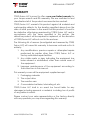
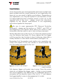
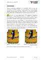
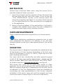
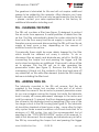
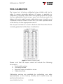
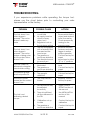
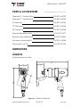
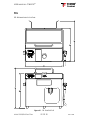
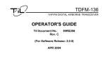
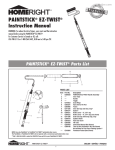
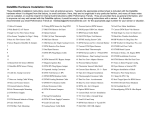
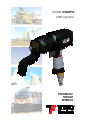
MODEL GT800PSS
USER MANUAL
PNEUMATIC
TORQUE
WRENCH
®
®
WWW.TORQFUSION.COM
USER MANUAL: GT800PSS©
2 OF 32
REV 1308
®
USER MANUAL: GT800PSS©
INTRODUCTION
Thank you for choosing TORQ Fusion as your torque tool
manufacturer. We understand that our customers have many
options when selecting their equipment and we truly appreciate
the opportunity to serve your bolting needs.
Our company firmly believes that the development of any
product starts with first understanding the needs of our customers
and apprehending the challenges they encounter with the
equipment they currently use. The TORQ Fusion design team then
tackles these challenges and implements innovative resolutions
in the design it develops. Next we prototype and evaluate our
designs gauging not only performance, but also robustness. Every
one of our designs goes through an exhaustive life test taking into
account every possible situation that might occur during normal
operation. As our tools enter the production phase, each unit is
calibrated throughout its operating range and our technical staff
reviews each calibration certificate before signing off and
releasing it.
Please take the time to review the rest of this manual, paying
special attention to the safety instructions associated with your
equipment.
If you have additional questions please feel free to contact your
sales representative or the factory by email at [email protected].
Thank you again for choosing TORQ Fusion!
WWW.TORQFUSION.COM
3 OF 32
REV 1308
®
USER MANUAL: GT800PSS©
TABLE OF CONTENTS
INTRODUCTION ..................................................................................................... 3
SAFETY .................................................................................................................... 5
PPE – (Personal Protective Equipment).......................................................................5
WARRANTY ............................................................................................................ 6
ABOUT THE TOOL .................................................................................................. 7
ABOUT THE FRL ...................................................................................................... 9
INSTALLATION ...................................................................................................... 11
OPERATING INSTRUCTIONS ............................................................................... 12
REMOVING AND INSTALLING THE TOOL EXTENSION ................................................13
REMOVING AND INSTALLING THE REACTION ARM ..................................................14
REMOVING AND INSTALLING THE OUTPUT DRIVE .....................................................15
INSTALLING THE IMPACT SOCKET ................................................................................16
DETERMINING THE SET PRESSURE .................................................................................17
LINEAR INTERPOLATION................................................................................................18
ADJUSTING THE SET PRESSURE .....................................................................................19
TIGHTENING ...................................................................................................................20
LOOSENING ...................................................................................................................21
BEST PRACTICES.............................................................................................................22
CARE AND MAINTENANCE ............................................................................... 22
TORQUE TOOL ...............................................................................................................22
FRL - CLEANING THE FILTER ..........................................................................................23
FRL - ADDING TOOL OIL ...............................................................................................23
FRL – REPLACING THE BATTERY....................................................................................24
TOOL CALIBRATION............................................................................................ 25
TROUBLESHOOTING............................................................................................ 26
TOOL SPECIFICATION......................................................................................... 27
PARTS & ACCESSORIES ...................................................................................... 28
DIMENSIONS ........................................................................................................ 28
GT800PSS ........................................................................................................................28
FRL ...................................................................................................................................29
TABLE OF FIGURES............................................................................................... 30
WWW.TORQFUSION.COM
4 OF 32
REV 1308
®
USER MANUAL: GT800PSS©
SAFETY
Safety is our primary concern and we want to ensure that our
customers enjoy the benefits of our tools while observing all
appropriate safety measures. Our tools are designed to be
operated by trained, skilled personnel.
Never disassemble or modify any portions of the tool or the FRL
supplied by TORQ Fusion – doing so may result in personal injury
and the product warranty to become void. Never strike or force
any portion of the torque wrench or the FRL as this may cause
damage to the equipment, create an unsafe situation and void
the warranty.
Reading this manual in its entirety is mandatory prior to
operating the equipment described in it. Additional training may
be required by your company’s training or safety advisor.
PPE – (Personal Protective Equipment)
Always wear protective eyewear when operating power
tools or entering an industrial environment.
Always wear hearing protection when operating power
tools or environmental conditions may exceed 85 dB(A) of noise.
Never place your hands or other body parts near the
reaction arm or any moving component – avoid pinch points.
It is a good practice to also wear work gloves, a hard hat, steel
toe shoes and any other protective equipment suitable for the
task being performed. Please consult with your company’s safety
advisor for more information.
WWW.TORQFUSION.COM
5 OF 32
REV 1308
®
USER MANUAL: GT800PSS©
WARRANTY
TORQ Fusion LLC is proud to offer a one year limited warranty for
your torque wrench and FRL assembly. We are confident in and
stand behind all of the products we manufacture and sell.
TORQ Fusion LLC warrants this product against all material and
workmanship defects for the duration specified above from the
date of initial purchase. In the event that this product is found to
be defective after being examined by TORQ Fusion LLC and in
accordance with the terms specified in this section, the
defective product will be repaired or replaced, at the discretion
of TORQ Fusion LLC without cost to the end user.
The following list of reasons (investigated and assessed by TORQ
Fusion LLC) will cause this warranty to become void and null in its
entirety:
1. Any modifications, previous repairs or attempted repairs
performed by parties other than TORQ Fusion LLC or
factory authorized repair facilities.
2. Any visible marks or signs indicating the equipment has
been abused or mishandled, other than normal wear of
the equipment.
3. Improper maintenance of the equipment according to
the instructions in this manual.
This warranty covers all the equipment supplied except:
1. Packaging materials
2. The output drive
3. The reaction arm
4. Consumables: batteries, lubricating oil, etc.
TORQ Fusion LLC shall in no event be found liable for any
damages including personal or material, including loss of profits
of any parties involved.
Please contact your sales representative or the factory directly
with any questions you may have regarding this warranty.
WWW.TORQFUSION.COM
6 OF 32
REV 1308
®
USER MANUAL: GT800PSS©
ABOUT THE TOOL
The GT800PSS is a single speed pneumatic torque wrench
designed to output a maximum of 800 ft-lbs (1,085 N-m) of
continuous torque. The tool is based on a multi-vane pneumatic
motor driving a high reduction multi-stage planetary gearbox.
When tightening or loosening fasteners requiring torque in the
range offered by this tool, there are many other methods
available: large breaker bars, manual torque multipliers, impact
wrenches or hydraulic wrenches. Breaker bars and manual
torque multipliers are the lowest cost option, but are labor
intensive and some have questionable torque accuracy. Impact
wrenches are relatively low cost, but have very poor torque
accuracy and generate a large amount of vibration and noise –
these factors may present serious health risks. Hydraulic wrenches
are very expensive, move relatively slow and require heavy
hydraulic pumps. Continuous torque pneumatic wrenches like
this one offer a good balance of power, speed, ergonomics and
cost.
Gearbox
Replaceable output
drive
Reaction arm
Trigger
Air flow adjustment
(disabled)
Air exhaust
Swivel air
connection
WWW.TORQFUSION.COM
Figure 1 - FRONT VIEW OF TOOL
7 OF 32
REV 1308
®
USER MANUAL: GT800PSS©
Serial number
label
Direction lever
Cushioned grip
Figure 2 - BACK VIEW OF TOOL
WWW.TORQFUSION.COM
8 OF 32
REV 1308
®
USER MANUAL: GT800PSS©
ABOUT THE FRL
The rotary vane motor of the tool produces a torque output
proportional to the air pressure it is supplied. In order to facilitate
adjustment of the torque output of the tool we supply a
designated FRL (Filter/Regulator/Lubricator) with each one.
To ensure that the torque output of this tool is as accurate as
possible, our FRL features a precision grade regulator and digital
pressure gauge. It is imperative that our tools only be operated
with the FRL units supplied by TORQ Fusion and the serial number
printed on the torque chart of the FRL matches the serial number
printed on the back of the tool.
Carry
handle
Tool storage
compartment
Torque
chart
Air pressure
adjustment
Pressure
gauge
Quick start
instructions
Battery
drawer
Swivel fitting
Air inlet
Air hose
Lubricator
Figure 3 - FRONT VIEW OF FRL
WWW.TORQFUSION.COM
9 OF 32
REV 1308
®
USER MANUAL: GT800PSS©
Tool
storage
Swivel fitting
Air Hose
Hose
storage
Rubber
feet
Figure 4 - BACK VIEW OF FRL
Lubricator
Filter
Regulator
Figure 5 - BOTTOM VIEW OF FRL
WWW.TORQFUSION.COM
10 OF 32
REV 1308
®
USER MANUAL: GT800PSS©
INSTALLATION
Installation of this tool must be performed by personnel
skilled and trained in the installation of pneumatic fittings.
The air supply will be connected to the FRL air inlet connection
(see Figure 3) via a pneumatic hook-up hose (not supplied) with
a minimum inside diameter of ½” or larger depending on the
distance from the compressor to the FRL. It is the responsibility of
the end user to ensure that a minimum air supply of 20 CFM @
115 PSI is delivered to the inlet connection of the FRL. Regardless
of hook-up hose size used, it must have a ½” MNPT fitting entering
the FRL. The installation of a shut-off valve is also recommended
upstream of the FRL.
Teflon tape must be used on the ½” MNPT fitting prior to installing
it to the FRL – TORQ Fusion does not recommend the use of any
other type of thread sealer. Proper torque for that size fitting must
be applied (50-60 ft-lbs [68-81 N-m] is common practice). No
backup wrench is required for installation as the FRL housing will
perform that function.
Un-coil the hose supplied with the FRL and connect the free end
to the swivel air connection at the base of the tool handle (see
Figure 1). To engage the fittings simply push the female fitting into
the male fitting while sliding back the knurled sleeve on the
female fitting – this is performed easier with the system depressurized but it may also be done under pressure.
To ensure sufficient air flow is being supplied to the tool, set the
FRL to the maximum pressure expected to be used – do not set
FRL to a pressure higher than indicated on the torque chart.
Install a socket onto the tool and use the tool to tighten a
fastener until the tool stops turning; while still depressing the tool
trigger check the digital pressure gauge on the FRL and ensure
the pressure displayed is within 1 psi of the pressure set at the
beginning of this paragraph. If the pressure drops more than 1 psi
a larger pneumatic hook-up hose and/or compressor is needed.
The torque tool is now installed.
WWW.TORQFUSION.COM
11 OF 32
REV 1308
®
USER MANUAL: GT800PSS©
OPERATING INSTRUCTIONS
Before starting completely read this manual and ensuring all
steps are understood. Any additional questions may be
answered by contacting your sales representative or the factory
by email at [email protected].
Ensure that the serial number on the back of the tool (see Figure
2) matches the serial number on torque chart located on the FRL
(see Figure 3).
Only ¾” or 1” impact sockets may be used with your torque tool,
properly installed with locking pins and retainer ring (see Figure
9). The tool is normally supplied with a ¾” square output drive,
unless a 1” square output drive was specified when purchased or
purchased separately. To change the size of the square drive see
REMOVING AND INSTALLING THE OUTPUT DRIVE section later in this
manual.
Figure 6 - IMPACT SOCKET
A reaction arm is necessary for the operation of the tool in order
to keep the gearbox housing from turning under extreme torque
output conditions. While operating, the reaction arm must be
resting against a robust stationary object (usually a nearby
fastener) capable of withstanding a reaction force equal to the
torque being generated by the tool. During operation the tool
handle may be rotated with respect to the gearbox housing as
not to transmit a reaction torque greater than a few foot pounds
to the operator of the tool.
WWW.TORQFUSION.COM
12 OF 32
REV 1308
®
USER MANUAL: GT800PSS©
REMOVING AND INSTALLING THE TOOL EXTENSION
Your tool may be equipped with an optional extension
depending on your application. The tool extension may be easily
removed and re-installed for increased tool versatility. It can be
installed in one of 8 positions on the spline of the gearbox housing
(see Figure 7). To install remove the set-screw located on the tool
extension using a 1/8” hex wrench. Slide out the tool extension
retaining pin – if the retaining pin does not slide out easily, it may
be pushed out with the 1/8” hex wrench. Ensure that the inside of
the gearbox receptacle is well lubricated as shown using lithium
or petroleum based grease. It is also a good practice to check
the lubrication on the extension journal by sliding out the inner
shaft of the extension – lubricate using lithium or petroleum
based grease and re-insert the inner shaft into the extension
housing. Fully engage the spline of the tool extension with the
spline of the gearbox housing and insert the tool extension
retaining pin. Replace the setscrew in the tool extension and retighten.
Gearbox
housing
spline
Lubricate
well
Setscrew
Reaction arm
retaining pin
Extension
journal
Figure 7 – TOOL EXTENSION INSTALLATION
To remove the tool extension, remove the set screw and tool
extension retaining pin, then slide the extension off the gearbox.
Be careful not to drop the inner shaft out of the assembly.
WWW.TORQFUSION.COM
13 OF 32
REV 1308
®
USER MANUAL: GT800PSS©
REMOVING AND INSTALLING THE REACTION ARM
The reaction arm may be installed in one of 8 positions on the
spline of the gearbox housing (see Figure 8). To install remove the
set-screw located on the reaction arm using a 1/8” hex wrench.
Slide out the reaction arm retaining pin – if the retaining pin does
not slide out easily, it may be pushed out with the 1/8” hex
wrench. Ensure that the output drive journal is well lubricated as
shown using lithium or petroleum based grease. Fully engage the
spline of the reaction arm with the spline of the gearbox housing
and insert the reaction arm retaining pin. Replace the setscrew in
the reaction arm and re-tighten.
Gearbox
housing
spline
Lubricate
well
Reaction
arm spline
Setscrew
Reaction arm
retaining pin
Figure 8 - REACTION ARM INSTALLATION
To remove the reaction arm, remove the set screw and reaction
arm retaining pin, then slide the reaction arm off the gearbox.
WWW.TORQFUSION.COM
14 OF 32
REV 1308
®
USER MANUAL: GT800PSS©
REMOVING AND INSTALLING THE OUTPUT DRIVE
The output drive (square drive) of the torque wrench is designed
to be field replaceable by the operator. Some of the reasons for
changing the output drive could be replacing the standard ¾”
square drive with the optional 1” square drive, replacing a
broken output drive or replacing the standard output drive with a
custom output drive. Regardless of the reason for replacing the
output drive, it’s as easy as removing one set screw.
Start by removing the reaction arm – see “REMOVING AND
INSTALLING THE REACTION ARM” in the previous pages. Continue
by simply pulling the square drive out.
Lubricate well
Figure 9 – OUTPUT DRIVE INSTALLATION
If removing a broken output drive the part should just slide out – if
it doesn’t, a pair of pliers or screw driver may be used.
To re-install an output drive, first lubricate the output drive journal
and quadrilobe areas as shown using a lithium or petroleum
based grease, engage output drive to gearbox and replace
reaction arm - see “REMOVING AND INSTALLING THE REACTION
ARM” in the previous pages.
WWW.TORQFUSION.COM
15 OF 32
REV 1308
®
USER MANUAL: GT800PSS©
INSTALLING THE IMPACT SOCKET
Only impact sockets must be used with your torque tool. They
must be properly installed with locking pins and retainer ring. The
output drive of your tool may be either ¾” or 1” depending on
how the tool was ordered or what additional accessories were
purchased with it.
First slide the retainer ring (o-ring) over the socket as shown in
Figure 10.
Locking pin hole
Retainer ring
Figure 10 - IMPACT SOCKET
Place the socket over the torque tool output drive (square drive)
aligning the locking pin hole with the hole in the output drive.
Slide in the locking pin (see Figure 11).
Socket groove
Locking pin
Figure 11 - SOCKET INSTALLATION
Finish the socket installation by rolling the retainer ring into the
socket groove to keep the locking pin in place.
WWW.TORQFUSION.COM
16 OF 32
REV 1308
®
USER MANUAL: GT800PSS©
DETERMINING THE SET PRESSURE
The GT800PSS is capable of operating under a wide range of
pressures, not exceeding 100 PSI. The toque output of the tool will
increase as the pressure on the FRL is set to higher values.
Based on the size and application of the fastener being
tightened, determine the appropriate torque required. Correlate
the required torque to the operating pressure by looking at the
torque chart located on the FRL (see Figure 3). The torque chart
lists pressure values in increments of 5 PSI. For most applications if
you cannot find the exact torque value on your chart, the closest
value will do – if more precise values are needed use one of the
formulas on the next page to calculate the set pressure.
The chart below is a sample of what the torque chart on your FRL
might look like. DO NOT use these values to set the pressure for
your tool, instead use the values on the chart provided with your
FRL.
Figure 12 - SAMPLE TORQUE CHART
WWW.TORQFUSION.COM
17 OF 32
REV 1308
®
USER MANUAL: GT800PSS©
LINEAR INTERPOLATION
Intermediate (interpolated) values may be calculated using
linear interpolation in order to maintain a high level of accuracy
for your tool.
Example: To set the tool at 650 ft-lbs when that value is not listed
on your chart use the following formula to determine the set
pressure for the FRL:
P = Pabove + (T − Tabove ) ×
Pbelow − Pabove
80 − 75
= 75 + (650 − 636) ×
≈ 76.9 psi
Tbelow − Tabove
673 − 636
Where:
P = set pressure for FRL
T = torque to achieve
P
T
above
above
650 would fall
between these lines
P
T
below
below
Figure 13 - CHART FOR INTERPOLATION EXAMPLE
A simpler but less accurate formula may also be used:
P=
T
Tabove
× Pabove =
650
× 75 ≈ 76.7 psi
636
WWW.TORQFUSION.COM
18 OF 32
REV 1308
®
USER MANUAL: GT800PSS©
ADJUSTING THE SET PRESSURE
Once the appropriate set pressure has been determined from
the torque chart and/or by using the information in the previous
sections, power on the pressure gauge and turn the air pressure
adjustment knob (see Figure 12) until the set pressure is achieved.
Always turn the knob clockwise to the set pressure. If the pressure
is too great turn the knob counter-clockwise until below set
pressure and then clockwise back up to set pressure.
Always make sure that the units displayed on the digital
pressure gauge match the units on the torque chart.
The motor must not be running while setting the pressure.
The tool may or may not be engaged with the fastener to be
tightened while adjusting the set pressure.
Pressure gauge
Torque chart
Air pressure adjustment
Figure 14 - PRESSURE SETTING
WWW.TORQFUSION.COM
19 OF 32
REV 1308
®
USER MANUAL: GT800PSS©
TIGHTENING
Once the reaction arm and appropriate size impact socket have
been installed and the correct pressure for your application has
been set, you are ready to tighten your fastener. Depending on
your application, you may be required to use lubrication on the
nut being tightened and a backup wrench on the nut on the
opposite end of the stud – please consult the instructions
supplied by the fastener manufacturer or the engineering
instructions supplied for the project.
Be sure to wear appropriate PPE (Personal Protective
Equipment) – please see the sections on “SAFETY” and “PPE” at
the beginning of this manual. Never place your hands or other
body parts near the reaction arm or any moving component.
Set the direction lever of the tool to “R”. Place the impact socket
over the fastener (see Figure 15). Slowly depress the tool trigger
until the reaction arm touches a robust, stationary object like a
nearby fastener or other similar metal feature (see Figure 16).
Remember that the gearbox and reaction arm assemblies can
rotate with respect to the tool handle to accommodate the
most favorable work angle for the tool.
Figure 15 - SOCKET OVER FASTENER
Figure 16 - REACTION ARM AGAINST
NEARBY FASTENER
Fully depress trigger until socket stops turning. Once the socket
stops do not depress the trigger again – doing so may increase
the torque applied to the fastener by an undesirable amount. If
necessary set the direction lever of the tool to “L” and depress
the trigger slightly to ease in disengagement of socket.
WWW.TORQFUSION.COM
20 OF 32
REV 1308
®
USER MANUAL: GT800PSS©
LOOSENING
When loosening a fastener it is generally safe to use the
maximum available torque. To do so power on the pressure
gauge and turn the air pressure adjustment knob until the digital
pressure gauge reads just under 100 PSI – do not exceed 100 PSI
or the tool may be damaged and operator injury may occur.
Be sure to wear appropriate PPE (Personal Protective
Equipment) – please see the sections on “SAFETY” and “PPE” at
the beginning of this manual. Never place your hands or other
body parts near the reaction arm or any moving component.
Set the direction lever of the tool to “L”. Place the impact socket
over the fastener (see Figure 17). Slowly depress the tool trigger
until the reaction arm touches a robust, stationary object like a
nearby fastener or other similar metal feature (see Figure 18).
Remember that the gearbox and reaction arm assemblies can
rotate with respect to the tool handle to accommodate the
most favorable work angle for the tool.
Figure 17 - SOCKET OVER FASTENER
Figure 18 - REACTION ARM AGAINST
NEARBY FASTENER
Fully depress trigger until the fastener is removed.
WWW.TORQFUSION.COM
21 OF 32
REV 1308
®
USER MANUAL: GT800PSS©
BEST PRACTICES
Several steps should be taken when using the torque tool to
maintain maximum torque accuracy:
1. If tool has not been used for a period of time, disconnect the
FRl hose from the tool, add a few drops of tool oil (see the
“TOOL SPECIFICATION” section of this manual) down the
swivel air connection (see Figure 1), re-connect the hose and
run it in either direction for a few seconds prior to engaging it
to the application.
2. Never re-torque a fastener to the same setting – it will result in
a higher than desired torque value. The tool is designed to
achieve proper torque only in dynamic situations.
CARE AND MAINTENANCE
There is minimal maintenance required for your torque wrench.
Before performing maintenance please be sure to read
and understand this manual in its entirety. If you still have
questions please contact your sales representative or the factory
directly.
TORQUE TOOL
The torque wrench is designed to generally be maintenance free
for the duration of its life, however depending on the duty cycle
and the environment in which it’s used in, there may be a few
parts requiring replacement.
The output drive has a limited life and after several thousand
cycles at full load, may require replacement – please see the
section entitled “REMOVING AND INSTALLING THE OUTPUT DRIVE”
for further instructions. Lubricate periodically – see Figure 9.
With severe duty cycles the air motor may require its vanes
replaced. We do not recommend this task be performed in the
field as it requires a high level of experience with air motors and a
re-calibration of the tool. Replacement vanes are available by
contacting your sales representative or the factory. Improper
installation of the motor vanes will void the warranty and may
cause an incorrect torque output or the tool to malfunction.
WWW.TORQFUSION.COM
22 OF 32
REV 1308
®
USER MANUAL: GT800PSS©
The gearbox is lubricated for life and will not require additional
grease to be added by the operator. After intensive use it may
need to be rebuilt, but this can only be performed by the factory
– please contact your sales representative or the factory for
additional information including cost.
FRL - CLEANING THE FILTER
The FRL unit contains a filter (see Figure 5) designed to protect
the air motor from exposure to water particles or debris from the
air line. The filter automatically drains the water collected in the
bowl onto the floor every time the air supply is cycled on or off,
therefore we recommend disconnecting the FRL unit from the air
supply at least once a day, depending on the amount of
moisture found in the air line.
Occasionally there might be some debris trapped by the filter
which should be cleaned out every 6 months. To do so
disconnect the air supply and eliminate any air left in the FRL by
connecting the torque tool and pressing the trigger until the
motor stops turning plus an additional 10 seconds to allow all the
air to escape. Turn the FRL unit on its side, revealing the
pneumatics inside (see Figure 5). Remove the filter bowl by
unscrewing it. Empty out the contents of the bowl and wipe off
any debris left on the white filter element (inside the FRL housing)
before re-installing the filter bowl.
FRL - ADDING TOOL OIL
The lubricator mounted in the FRL unit ensures that the air
supplied to the torque tool contains a fine mist of oil which
lubricates the vanes of the air motor to prevent premature wear.
As you can imagine running the torque tool while the lubricator
bowl is empty will cause permanent damage to the motor and
void the warranty. To prevent that from happening please check
the oil level in the lubricator bowl by inspecting it thru one of the
two large cutouts in the FRL housing (see Figure 3). The lubricator
oil should be checked at least once a day – more often for high
duty cycles. Under normal conditions a full bowl should last for a
minimum of 1,000 cycles. Use only the recommended tool oil
specified in the “TOOL SPECIFICATION” section of this manual. To
add oil first disconnect the air supply and eliminate any air left in
the FRL by connecting the torque tool and pressing the trigger
WWW.TORQFUSION.COM
23 OF 32
REV 1308
®
USER MANUAL: GT800PSS©
until the motor stops turning plus an additional 10 seconds to
allow all the air to escape. Unscrew the lubricator bowl, fill to the
“MAX” mark on the bowl and screw the bowl back into the unit.
FRL – REPLACING THE BATTERY
The digital pressure gauge uses a standard 9V battery which will
need to be replaced periodically. The battery drawer is located
on the left side of the FRL housing, next to the air inlet connection
(see Figure 3). To access the drawer a small screw driver will be
required. Insert the tip of the screw driver in the notch of the
battery drawer and push down to pry it open. Slide out the rawer
and remove the old battery by pulling it out vertically. Insert the
new battery (the battery can only fit one way to maintain
correct polarity). Push in the battery drawer into the FRL housing
until it clicks.
WWW.TORQFUSION.COM
24 OF 32
REV 1308
®
USER MANUAL: GT800PSS©
TOOL CALIBRATION
The torque tool is factory calibrated when initially sold, but in
order to ensure accurate delivery of torque, a periodic recalibration is required. TORQ Fusion recommends that the torque
tool be calibrated at least once a year. Tools that are used at a
higher duty cycle might require calibration every 6 months or at
a different interval. Please consult with your sales representative
or the factory for the appropriate interval.
The torque chart below is used to illustrate the information that is
normally generated at the time of calibration.
Figure 19 - SAMPLE TORQUE CHART
Please note that all torque charts will include the following
information:
• Tool model number
• Tool serial number
• Pressure/Torque correlation values
• Calibration date
Calibration services are available by contacting your sales
representative or the factory directly and should never be
performed elsewhere.
WWW.TORQFUSION.COM
25 OF 32
REV 1308
®
USER MANUAL: GT800PSS©
TROUBLESHOOTING
If you experience problems while operating the torque tool,
please use the chart below prior to contacting your sales
representative or the factory.
PROBLEM
POSSIBLE CAUSE
1.
The tool doesn’t run
when trigger is
pressed – the motor
doesn’t make any
noise
2.
3.
1.
The tool doesn’t run
when trigger is
pressed – the motor
makes a hissing noise
but the output drive
doesn’t turn
The tool makes an
abnormal or irregular
sound while running
The pressure gauge
does not power on
The motor sounds
normal but the socket
doesn’t turn
The tool is not
delivering desired
torque
WWW.TORQFUSION.COM
2.
3.
1.
2.
1.
2.
1.
Air supply not
connected
Air supply hose has
a kink or heavy
object on it
Regulator is set on
the minimum setting
The tool is engaged
with a fastener and
has reached the
max torque
The gearbox or
motor are defective
The direction lever is
incorrectly set
The motor is not
lubricated
The gearbox or
motor are defective
The battery is dead
The gauge is
defective
The output drive is
broken
ACTION
1.
2.
3.
1.
2.
3.
1.
2.
1.
2.
1.
Connect air supply
Remove kink/heavy
object and replace
hose if necessary
Check pressure by
turning on the
pressure gage
Remove tool from
fastener and press
trigger to ensure
proper operation
Contact factory for
repair
Move lever to either
“R” or “L” positions
Check lubricator
level
Contact factory for
repair
Replace battery
Contact factory for
repair
Replace, contact
factory for spare
1.
FRL air pressure may
be adjusted
incorrectly
1.
Read TORQUE
SETTING section of
this manual
2.
There is insufficient
air flow delivered to
the FRL
2.
See INSTALLATION
section of this
manual
3.
Calibration not up
to date
3.
Contact factory for
calibration
4.
The gearbox or
motor are defective
4.
Contact factory for
repair
26 OF 32
REV 1308
®
USER MANUAL: GT800PSS©
TOOL SPECIFICATION
Output Drive
¾” SQ /w pin retainer1
800 ft-lbs
Max Torque (@ 0 RPM)
Max Speed (no load)
12 RPM
Max Air Pressure
115 PSI2
Max Air Consumption
20 CFM3
Air Connection (@FRL)
½” FNPT
Max Noise Level
86 dB(A)4
Tool Weight (w/o reaction arm & output drive)
6.4 lbs
Reaction Arm Weight
2.9 lbs
¾” Output Drive Weight
0.4 lbs
Optional 6” Tool Extension Weight
4.6 lbs
Optional 12” Tool Extension Weight
6.9 lbs
Optional 18” Tool Extension Weight
9.1 lbs
FRL Weight
13 lbs
FRL Battery
9V (PP3)
Tool Oil
Marvel Air Tool Oil (MMO80 or MMO085)5
1 Tool
may also be supplied with a 1” square drive with pin retainer
Never set FRL to a pressure higher than indicated on the torque chart
3 To achieve maximum operating range of the tool air supply must be at least 20
CFM @ 115 psi
4 Maximum noise level at 100 PSI without a load; noise levels under load are lower
5 May be purchased from TORQ Fusion or directly from a distributor
2
WWW.TORQFUSION.COM
27 OF 32
REV 1308
®
USER MANUAL: GT800PSS©
PARTS & ACCESSORIES
Visit WWW.TORQFUSION.COM for more info
Standard ¾” Square Drive
P/N 001-A-0053
Standard 1” Square Drive
P/N 001-A-0054
6” Extension
P/N 001-A-0044
12” Extension
P/N 001-A-0043
18” Extension
P/N 001-A-0038
Standard Reaction Arm
P/N 001-F-0217
Reaction Arm Weld Blank
P/N 001-F-0205
Accessory Mounting Kit
P/N 001-A-0068
Pneumatic Tool Oil
P/N 001-P-0120
DIMENSIONS
GT800PSS
All dimensions in inches
Figure 20 - GT800PSS DIMENSIONS
WWW.TORQFUSION.COM
28 OF 32
REV 1308
®
USER MANUAL: GT800PSS©
FRL
All dimensions in inches
Figure 21 - FRL DIMENSIONS
WWW.TORQFUSION.COM
29 OF 32
REV 1308
®
USER MANUAL: GT800PSS©
TABLE OF FIGURES
Figure 1 - FRONT VIEW OF TOOL ........................................................................................7
Figure 2 - BACK VIEW OF TOOL.........................................................................................8
Figure 3 - FRONT VIEW OF FRL ............................................................................................9
Figure 4 - BACK VIEW OF FRL............................................................................................10
Figure 5 - BOTTOM VIEW OF FRL.......................................................................................10
Figure 6 - IMPACT SOCKET ................................................................................................12
Figure 7 – TOOL EXTENSION INSTALLATION.....................................................................13
Figure 8 - REACTION ARM INSTALLATION .......................................................................14
Figure 9 – OUTPUT DRIVE INSTALLATION..........................................................................15
Figure 10 - IMPACT SOCKET..............................................................................................16
Figure 11 - SOCKET INSTALLATION ...................................................................................16
Figure 12 - SAMPLE TORQUE CHART................................................................................17
Figure 13 - CHART FOR INTERPOLATION EXAMPLE ........................................................18
Figure 14 - PRESSURE SETTING...........................................................................................19
Figure 15 - SOCKET OVER FASTENER
Figure 16 - REACTION ARM AGAINST ..........20
Figure 17 - SOCKET OVER FASTENER
Figure 18 - REACTION ARM AGAINST ..........21
Figure 19 - SAMPLE TORQUE CHART................................................................................25
Figure 20 - GT800PSS DIMENSIONS ..................................................................................28
Figure 21 - FRL DIMENSIONS..............................................................................................29
WWW.TORQFUSION.COM
30 OF 32
REV 1308
®
USER MANUAL: GT800PSS©
TOOL INFORMATION
DATE PURCHASED:
SERIAL NUMBER:
INITIAL CALIBRATION:
NEXT CALIBRATION:
NEXT CALIBRATION:
NEXT CALIBRATION:
NEXT CALIBRATION:
NEXT CALIBRATION:
NEXT CALIBRATION:
ASSET NUMBER:
OTHER:
NOTES:
WWW.TORQFUSION.COM
31 OF 32
REV 1308
®
USER MANUAL: GT800PSS©
User Manual p/n: 001-F-0194
Patents Pending
Copyright © 2011-2013 TORQ Fusion LLC
WWW.TORQFUSION.COM
32 OF 32
REV 1308