1
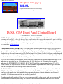
IMSAI 8080 CPA Front Panel
The official home page of
IMSAI
®
a registered trademark of the Fischer-Freitas Company
© 1999 Thomas Fischer All rights reserved worldwide
IMSAI CPA Front Panel Control Board
c. 1999 Thomas Fischer
All rights reserved worldwide
NOTE: The following text is copied directly from the original CPA manual, with minor correction of
grammar and spelling. It does not discuss later modifications that corrected compatibility and reliability
issues. Those modifications will be included when this text is revised. Also note that the link to schematic
is disabled until a practical means of depicting the graphic can be implemented. Specific questions can
be e-mailed to: [email protected]
Functional Description- The CP-A board is the operator's panel for the IMSAI 8080 System. It
includes operator switches, indicator lights and all logic necessary to operate the IMSAI 8080 System.
The panel is completely self-contained and plugs into the back plane's 100-pin edge connector. With this
design it is not necessary to mount the CP-A at the front of the cabinet. Instead, the board can be plugged
(via an extender card) into any available slot in the backplane. The switches are included [with] the front
panel whether it is mounted in the front of the panel or not.
A full set of 16 address switches and 6 control function switches accept operator control and input. LED
indicators are provided for the 16 bit address bus, the 8 bit data bus, the 8 bit status byte (control
indicators for INTERRUPTS, ENABLED, RUN, WAIT and 8 bits of programmed output. The CP-A
board contains the logic necessary to drive the 8 programmed output indicators and the logic needed to
read an 8-bit input byte from the high-order address switches.
The DATA BUS indicators are run from the bi-directional portion of the data bus (via a flat cable to the
MPU board) and show data either being read or written by the 8080 processor. The indicators on the
panel are wide-angle-view light emitting diodes mounted behind a contrast-enhancing acrylic panel
assembly. All indicators and switches are explicitly marked.
The photographically produced labels are very clear, protected by clear acrylic, and can never wear off.
Bit positions are numbered, and binary bit values are labeled for both hexadecimal and octal formats.
file:///C|/My Documents/My Webs/imsai/Tech_Support/Board_History/CPA_rev4.htm (1 of 4) [8/21/1999 11:09:54 PM]
IMSAI 8080 CPA Front Panel
Special labels may be easily inserted to identify special functions for the programmed output port.
Switches on the panel are high-quality paddle switches, and are color-coded for easy and error free use.
For situations in which it is not desired to locate the operator's panel at the cabinet front (such as use of
the IMSAI 8080 as a dedicated controller), the CP-A front panel may be inserted (via extender card) into
any back plane slot. In this arrangement, programs may be easily tested and debugged without
time-consuming mounting and un-mounting of the front panel. For these applications, the front slot of
the machine can be reserved for the parallel I/O board with its LED indicators showing through the front
panel mask.
Theory of Operation- The CP-A front panel assembly provides machine status indicators,
user-controlled switches, and control functions to the IMSAI 8080 operator. The CP-A board
communicates with the MPU-A microprocessor and other boards through the 8080 back plane and,
additionally, connects (via 16 conductor flat cable) to the bi-directional data bus of the 8080
microprocessor. The CP-A panel-uses 44 Light Emitting Diodes as front panel indicators. Many of these
indicators directly correspond to signal levels on the IMSAI 8080 back plane, and are driven directly
from the bus with no intervening logic. Indicators in this group are the 16 Address Bus LED's, the 8
STATUS byte LED's, the INTERRUPT ENABLED LED, the WAIT LED, and the HOLD LED.
The 8080 microprocessor chip's bi-directional data bus levels (provided by a 16-conductor cable) are
displayed on the DATA bus indicators via the 74LS04 (low power schottky hex inverter) sections. Also
driven from the bi-directional bus is the 8212 8-bit latch used to drive the PROGRAMMED OUTPUT
indicators. The RUN indicator is driven directly from the run/stop flip-flop (74107) on the CP-A Board.
The 16 ADDRESS-PROGRAMMED INPUT and ADDRESS-DATA switches allow the operator to
place desired value (program, data, and addresses) on the 8080's bi-directional bus. As shown on the
schematic, these switches connect 7405 (open collector) inverters to the bus in a wired-AND
configuration. Pull-up resistors on the MPU Board ensure that the bus levels are all high unless any
inverter on any one of the bus lines goes low. Thus, if an inverter goes low, (this condition will be
discussed shortly) the address switch can be used to put either a high or low value on that line.
The function switches provide the operator with direct control of the microprocessor. The RUN/STOP
switch controls the X-READY line via the RUN/STOP flip-flop. If the switch is set to RUN, on the next
falling edge of the Phase II clock, the RUN and X-READY lines are set high. If the switch is set to
STOP, the high STOP value and the Phase II clock are NANDed (Ul6) and this value NANDed with the
DATA OUT 5 bit (fetch/status) and the PROCESSOR SYNC line. Thus, when the processor is fetching a
new instruction, the RUN/STOP flip-flop will be reset, the processor X-READY line goes low, and the
processor stops.
Several CP-A function switches operate by providing the 8080 with an instruction, executing the
instruction, and then stopping the processor on the next cycle. The open collector 7405's and support
gating put these instructions on the 8080's bi-directional bus. The EXAMINE function uses a jump
instruction (hex C3) followed by two bytes of the address selected on the front panel switches. This
operation causes the processor to jump to the selected address and, then, the processor is stopped during
the next cycle. When stopped, the processor was reading the selected byte from memory as if it were
going to execute it. Therefore, the processor stops with the desired address displayed on the address bus
and the contents of that address is displayed on the data bus. If the RUN switch is operated at this time,
file:///C|/My Documents/My Webs/imsai/Tech_Support/Board_History/CPA_rev4.htm (2 of 4) [8/21/1999 11:09:54 PM]
IMSAI 8080 CPA Front Panel
the processor will continue to pull the selected byte from memory and execute it.
The EXAMINE NEXT and DEPOSIT NEXT switches use similar schemes and the NO-OP (hex 00 or
octal 000) instruction to increment the address. Much of the remaining logic of the CP-A is used to
sequence these commands to provide the desired functions. The RUN/STOP flip-flop line, the SINGLE
STEP line, the EXAMINE line, and the EXAMINE NEXT-line are all input to an OR-gate controlling
the X-READY line. (The X-READY line must be high for the processor to run its function is identical to
the P-READY line used by the memory and I/O boards. The X-READY line is reserved for use of the
front panel to avoid conflicts of two gates driving the same backplane line). During each of these
functions, the processor is permitted to execute an instruction, and then is stopped in the next cycle in a
manner similar to the RUN/STOP flip-flop cycle described earlier.
For the SINGLE STEP function, a one-shot, triggered by the SINGLE-STEP switch, is used to produce a
pulse and the trailing edge of that pulse is used to set a flip-flop, which controls the SINGLE STEP line.
This permits the processor to execute the present instruction. The SINGLE STEP flip-flop is reset by the
occurrence of the sync pulse on the following instruction, thus causing the SINGLE STEP level to be
removed and the processor to stop on the following cycle.
The EXAMINE-NEXT flip-flop is similarly controlled by the leading edge of a pulse from a one-shot
driven by either the DEPOSIT NEXT or EXAMINE NEXT switch. The output of the flip-flop is used
both to put the NO-OP (hex 00 or octal 000) onto the bi-directional data bus, and also to provide the
READY signal so that the processor will execute the instruction. It is reset by the sync pulse on the
following cycle, thus stopping the processor again.
The EXAMINE function involves a 4-step sequence produced by two flip-flops arranged as a counter.
The pulse produced by the EXAMINE switch's one-shot starts the counter and on the first count, the
jump instruction is inserted on the data bus. On successive counts of the two bit counter, the lower and
upper address byte are inserted on the data bus in turn, and on the 4th count (that is, when the counter is
back to 0), the processor is again stopped by the removal of the READY line. Thus, the EXAMINE logic
provides the processor with the jump instruction and the two address bytes that the processor expects
after a jump instruction and stops the processor during the fetch of the designated memory byte.
Similarly, the DEPOSIT switch, when operated, produces a pulse from the DEPOSIT one-shot, which is
buffered to the MEMORY WRITE line on the backplane. The leading edge of this pulse also starts a
second one-shot with a much longer period which puts the data from the data switches on to the data bus
for the duration of the longer pulse. The DEPOSIT one-shots are triggered either by the operation of the
DEPOSIT switch or by the trailing edge of the DEPOSIT NEXT one-shot so that the DEPOSIT function
will operate at the end of the EXAMINE NEXT cycle. The 7427 gate in U15.5 is used to ensure that
during the time the front panel is inserting any information on the bi-directional data bus, the MPU-A
board's bi-directional data bus driver is not also trying to drive the bus at the same time. The inputs to
this gate are the DATA-ON line, the EXAMINE NEXT line and the EXAMINE line. These are the three
functions during which the front panel is transferring data or instructions to the bus. The inputs to the
7405 open-collector inverter bus drivers are the lines NO-OP, C3, HAD, and LAD. These levels are
ANDed with the PDBIN signal so that the information appears on the bus during the time the processor
is expecting to see it there.
The input port from the high order address switches is implemented simply by decoding the address FF
and ANDing it with the DBIN signal so that switch values appear on the data bus during the time that the
file:///C|/My Documents/My Webs/imsai/Tech_Support/Board_History/CPA_rev4.htm (3 of 4) [8/21/1999 11:09:54 PM]
IMSAI 8080 CPA Front Panel
processor is expecting information from the port FF. The same address decode signal is ANDed with the
STATUS OUT line to enable the 8212 8 bit latch which drives the PROGRAMMED OUTPUT
indicators. The information on the bi-directional data bus is then latched onto the output port at the time
of the processor write strobe. The STATUS WORD DISABLE line (SSWDSB, pin 53 backplane is gated
to ensure that no conflicts are created between the bi-directional bus drivers on the MPU and CP-A
boards. This signal is controlled by the same gating that places the high order address switch values on
the data for a front panel (address hex FF) read.
The STATUS WORD DISABLE line, Pin 53 in the backplane, is also run by the signal which puts the
high order address switches onto the data bus for the port FF read instruction so that the bi-directional
data bus is not being driven by the bi-directional drivers on the MPU board at the same time that the front
panel is inserting the switch information on the data bus.
The RESET switch directly grounds the RESET line on the backplane which is detected by the MPU
board and processed to form a RESET pulse which reappears on the backplane as a Power On Clear.
When the RESET switch is thrown to EXTERNAL CLEAR, the switch directly grounds the
EXTERNAL SWITCH line on the backplane. There is a diode between the RESET line and the
EXTERNAL CLEAR line so that during a reset operation an EXTERNAL CLEAR is also generated.
file:///C|/My Documents/My Webs/imsai/Tech_Support/Board_History/CPA_rev4.htm (4 of 4) [8/21/1999 11:09:54 PM]