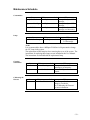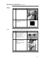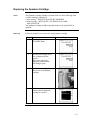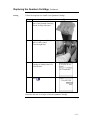
1
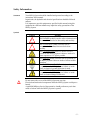
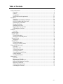
User Manual Milli-Q Reference System About this User Manual Purpose This User Manual is intended for use with a Milli-Q® Reference Water Purification System. This User Manual is a guide for use during the installation, normal operation and maintenance of a Milli-Q Reference Water Purification System. It is highly recommended to completely read this manual and to fully comprehend its contents before attempting installation, normal operation or maintenance of the Water Purification System. If this User Manual is not the correct one for your Water Purification System, then please contact Millipore. Terminology The term “Milli-Q Reference Water Purification System” is replaced by the term “System” for the remainder of this User Manual unless otherwise noted. Document Rev. 0, 03/2009 About Millipore£ Telephone See the business card(s) on the inside cover of the User Manual binder. Internet Site Address www.millipore.com/bioscience Manufacturing Site Millipore SAS 67120 Molsheim FRANCE -2- Legal Information Notice The information in this document is subject to change without notice and should not be construed as a commitment by Millipore Corporation. Millipore Corporation assumes no responsibility for any errors that might appear in this document. This manual is believed to be complete and accurate at the time of publication. In no event shall Millipore Corporation be liable for incidental or consequential damages in connection with or arising from the use of this manual. We manufacture and sell water purification systems designed to produce pure or ultrapure water with specific characteristics (PS/cm, T, TOC, CFU/ml, Eu/ml) when it leaves the water purification system provided that the System is fed with water quality within specifications, and properly maintained as required by the supplier. We do not warrant these systems for any specific applications. It is up to the end user to determine if the quality of the water produced by our systems matches his expectations, fits with norms/legal requirements and to bear responsibility resulting from the usage of the water. Warranty Millipore Corporation (“Millipore”) warrants its products will meet their applicable published specifications when used in accordance with their applicable instructions for a period of one year from shipment of the products. MILLIPORE MAKES NO OTHER WARRANTY, EXPRESSED OR IMPLIED. THERE IS NO WARRANTY OF MERCHANTABILITY OR FITNESS FOR A PARTICULAR PURPOSE. The warranty provided herein and the data, specifications and descriptions of Millipore products appearing in Millipore’s published catalogues and product Literature may not be altered except by express written agreement signed by an officer of Millipore. Representations, oral or written, which are inconsistent with this warranty or such publications are not authorized and if given, should not be relied upon. In the event of a breach of the foregoing warranty, Millipore’s sole obligation shall be to repair or replace, at its option, the applicable product or part thereof, provided the customer notifies Millipore promptly of any such breach. If after exercising reasonable efforts, Millipore is unable to repair or replace the product or part, then Millipore shall refund to the customer all monies paid for such applicable product or part. MILLIPORE SHALL NOT BE LIABLE FOR CONSEQUENTIAL, INCIDENTAL, SPECIAL OR ANY OTHER INDIRECT DAMAGES RESULTING FROM ECONOMIC LOSS OR PROPERTY DAMAGE SUSTAINED BY ANY CUSTOMER FROM THE USE OF ITS PRODUCTS. Continued on next page -3- Legal Information Continued Trademarks Millipore, Elix, Q-Gard, Quantum, Milli-Q, BioPak, EDS-Pak, Millipak and Millipore Express are registered trademarks of Millipore Corporation. The “M” Mark and RiOs are trademarks of Millipore Corporation. All other trademarks are trademarks of their respective manufacturers. Copyright ¤ 2008 MILLIPORE CORPORATION. PRINTED IN FRANCE. ALL RIGHTS RESERVED. THIS BOOK OR PARTS THEREOF MAY NOT BE REPRODUCED IN ANY FORM WITHOUT THE WRITTEN PERMISSION OF THE PUBLISHERS -4- Safety Information Statement Your Milli-Q System should be installed and operated according to the instructions in this manual. In particular, the hydraulic and electrical specifications should be followed and met. It is important to use this equipment as specified in this manual; using this equipment in a different manner may impair the safety precautions of the Milli-Q System. Symbols Symbol Meaning ! This HAZARD symbol is used to refer to instructions in this manual that need to be done safely and carefully. This ATTENTION symbol is used to refer to instructions in this manual that need to be done carefully. This UV RADIATION sticker is used to refer to a position on the Milli-Q System Cabinet or inside of it where exposure to UV light is possible. This DANGER sticker is used to refer to a position on the Milli-Q System Cabinet or inside of it that could be hazardous. This ELECTRICAL GROUND sticker is used to refer to a position on the Milli-Q System Cabinet or inside where an electrical ground connection is made. This ELECTRICAL DANGER sticker is used to refer to a position on the Milli-Q System Cabinet or inside where an electrical danger could exist. ! Do not remove the covers of the Milli-Q System at any time. Electrical and mechanical components inside the Milli-Q System could pose a hazard. A qualified Millipore Service Representative should perform any work that needs to be done while the Milli-Q System is opened. -5- Table of Contents Product Information ....................................................................................................................8 Overview .............................................................................................................................8 Cabinet ................................................................................................................................9 Consumables .....................................................................................................................14 Specifications and requirements........................................................................................16 Installation.................................................................................................................................19 Overview ...........................................................................................................................19 Alarms generated during installation ................................................................................20 POD Unit, tubing and power cord.....................................................................................21 Installing the Q-Gard Pack................................................................................................24 Rinsing the System............................................................................................................27 Installing a POD Pak .........................................................................................................29 Registering UV Lamp timer ..............................................................................................31 Calibrating the Flowrate....................................................................................................33 Software ....................................................................................................................................35 Overview ...........................................................................................................................35 Software Map ........................................................................................................................36 Standby Mode .......................................................................................................................37 General information ..........................................................................................................37 Description of Standby Menu ...........................................................................................38 Manager Menu ......................................................................................................................40 Description ........................................................................................................................40 Ready Mode ..........................................................................................................................43 General information ..........................................................................................................43 Description of Ready Menu ..............................................................................................44 Using the Milli-Q System .........................................................................................................47 Overview ...........................................................................................................................47 Dispensing water ...............................................................................................................48 Viewing water quality .......................................................................................................51 Viewing Operation ............................................................................................................52 Viewing Consumable Status .............................................................................................54 Calling Millipore ...............................................................................................................55 Viewing Information .........................................................................................................56 Maintenance ..............................................................................................................................58 Overview ...........................................................................................................................58 Maintenance Schedule.......................................................................................................59 Replacing the Q-Gard Pack...............................................................................................60 Replacing the Quantum Cartridge.....................................................................................63 Replacing a POD Pak........................................................................................................67 Cleaning the Inlet Strainer.................................................................................................70 Calibrating the Flowrate....................................................................................................73 -6- Alarms .......................................................................................................................................74 Overview ...........................................................................................................................74 Alarm Information.............................................................................................................75 Summary of Alarm messages............................................................................................79 Alerts .........................................................................................................................................81 Overview ...........................................................................................................................81 Alert information...............................................................................................................82 Summary of Alert messages..............................................................................................87 Ordering Information ................................................................................................................89 Consumables, Accessories and Systems ...........................................................................89 -7- Product Information Overview Purpose This chapter contains topics related to the System. Some of the more important topics in this chapter are: x installation requirements, x consumable information, and x dimensions of various components of the System Contents This chapter contains the following topics: Topic Cabinet Consumables Specifications and requirements See Page 9 14 16 -8- Cabinet Overview A F G B C H D E Item A B C D E F G H Main Display function Description/Name Point Of Delivery (POD) POD Pak POD Arm Connections for tubings, power cord, level sensor and other cables Q-Gard Pack POD Mast Main Display Quantum Cartridge The Main Display is used to navigate the System software. Continued on next page -9- Cabinet, Continued Details of the Main Display 1 3 2 Item 1 2 3 Right Description LEDs Main LCD Main Keypad The use of the Right Keypad button is shown below. It is used to move to the next screen. In this example, the system is changed from STANDBY Mode to READY Mode. Diagram 1 Action Press Diagram 2 . The use of the Left Keypad button is shown below. It is used to move to the former screen. Left Diagram 1 Action Press Diagram 2 . Continued on next page - 10 - Cabinet, Continued The use of the Up Keypad button is shown below. It is used to scroll up in a menu. Up Diagram 1 Action Press Diagram 2 . The use of the Down Keypad button is shown below. It is used to scroll down in a menu. Down Diagram 1 Action Press Diagram 2 . The use of the Validate Keypad button is shown below. It is used to confirm a parameter modification. Validate Diagram 1 Action Press Diagram 2 . Continued on next page - 11 - Cabinet, Continued READY Mode – water quality values The READY Mode screen display is explained below. Diagram Explanation In this example, the water dispensed from the POD Unit has: x a resistivity of 18.2 M:.cm, x is temperature compensated (TC) at 25°C, x a temperature of 24.9°C, and x the TOC value is: not indicated with a Milli-Q Reference System, and indicated with a Milli-Q Reference C+ System. NOTE: This Milli-Q Reference System does not have a built-in TOC indicator and therefore does not display a TOC value. Should you wish to have a display of the TOC value, please contact Millipore and inquire about availability of the TOC Indicator Upgrade Kit. In this example, there are no water quality measurements to display. The water quality is only displayed when it is actually measured during water delivery or recirculation. LEDs The LEDs are described below. Item Green LED Yellow LED Red LED Description System is operating within specifications. An Alert is present. An Alarm is present. NOTE: If an Alarm and an Alert are present at the same time, then only the red LED is lit. The red and yellow LEDs are never lit at the same time. Continued on next page - 12 - Cabinet, Continued Port and cables The port and cable connections are explained below. 6 5 4 3 1 Item 1 2 3 2 Description Feedwater port Ethernet connection (maximum 5 VDC) Level Sensor (maximum 5 VDC) Item Description 4 Termination Plug connection (maximum 5 VDC) 5 Accessories connection (maximum 24 VDC) 6 Power Entry connection (100-240 VAC) - 13 - Consumables Flow diagram The water flow through a System is shown here in a flow diagram. The various consumables are described below. B A Item A B C D Q-Gard Pack D Description Q-Gard Pack UV 185 nm Lamp Quantum Cartridge POD Pak The Q-Gard Pack is used to remove ions and organic molecules from the feedwater. Item Q-Gard T1 Pack Q-Gard T2 Pack Q-Gard T3 Pack UV 185 nm Lamp C Description The Q-Gard T1 Pack is used when the feedwater comes from RO, distillation or Electrodeionisation (EDI). An example of RO or EDI feedwater is the water coming from either a Millipore RiOs System or Elix® Water Purification System. This type of feedwater typically has some ions but contains little organic, particulate and colloidal contamination. The Q-Gard T2 Pack is used whenever the feedwater comes from a source other than mentioned above and has a Fouling Index 5. The Q-Gard T3 Pack is used whenever the feedwater comes from a source other than mentioned above and has a Fouling Index ! 5. The dual wavelength UV 185 nm Lamp emits light at 185 nm and at 254 nm. The UV 185 nm Lamp kills bacteria and reduces the level of organic molecules in the water. Continued on next page - 14 - Consumables, Continued Quantum Cartridge The Quantum Cartridge removes trace levels of ions and organic molecules. Item Quantum TIX Cartridge Quantum TEX Cartridge POD Pak Description The Quantum TIX Cartridge contains only ion exchange resin. This type of Quantum Cartridge is used when maintaining absolutely trace levels of ions is critical. The Quantum TEX Cartridge contains ion exchange resin and synthetic carbon. These purification media are used when the Milli-Q£ Water needs to have both trace levels of ions and trace levels of organic molecules. The POD Pak is the final water purification device. It is attached to the Point of Delivery outlet. The POD Pak provides additional quality and insurance that trace contaminants related to specific applications are removed just before ultrapure water is delivered. - 15 - Specifications and requirements Milli-Q Water quality The water delivered from a POD Unit has the following characteristics. Parameter Resistivity TOC Particulates > 0.22 Pm** Bacteria** Pyrogens* RNases* DNases* Flow Rate** Specification 18.2 d5 <1 < 0.1 < 0.001 < 0.01 <4 0.05 – 2 Units M:.cm @25°C ppb Particulates/mL cfu/mL Eu/mL ng/mL pg/PL L/min (*) With BioPak£ Final Filter (**) With Millipak£ or BioPak Final Filter NOTE: These specifications are valid for Elix water feed within specification and for routine operation. Some specifications may not be achieved at start-up. Weight The various weights are found in the table below. Item Milli-Q Reference System Electrical Operating Weight 19.5 kg Dry Weight 14.5 kg Shipping Weight 19 kg The electrical specifications and data are found in the table below. Parameter Voltage Frequency Main Fuse Power Used Power Cord Length Electrical Ground Power Cord use Value 100-230 VAC r10% 50-60 Hz r10% 2.5 Amp Time Lag; 5 mm x 20 mm; 250 V safety voltage. The fuse should be serviced by a qualified Millipore Service Representative. 125 VA 2.5 metres Earth Grounded The System is powered on and off by removing the power cord from the wall outlet. The power cord should be plugged into a wall outlet that is accessible. Continued on next page - 16 - Specifications and requirements, Continued Dimensions 763 mm 500 mm 360 mm 416 mm 458 mm 552 mm 422 mm 783 mm Materials of construction Please contact Millipore for a list of the Materials of Construction. Continued on next page - 17 - Specifications and requirements, Continued Feedwater The Feedwater requirements are listed here. Parameter Type Conductivity Pressure Temperature Maximum TOC Fouling Index pH Environmental Value Pre-treated water including one or several of the following technologies: x RO x RO + EDI x RO + DI x Distillation, and x DI. < 100 PS/cm @ 25°C 0 bar < P < 0.3 bar 5°C < T < 35°C < 50 ppb <5 4 < pH < 10 The Environmental requirements are listed here. Parameter Altitude Ambient operating temperature Ambient storage temperature Installation Category Location Pollution Degree Relative humidity during storage and operation Value < 3000 metres 4 – 40°C 4 – 40°C II The System is intended for indoor use only. 2 Maximum relative humidity 80% for temperatures up to 31°C decreasing linearly to 50% relative humidity at 40°C. Noise Level The noise level is < 50 dB at a distance of 1 metre. Consumables The minimum consumables required for installation are listed here. Note that these items are not shipped with the System and must be ordered separately: x Q-Gard Pack, x Quantum Cartridge, and x POD Pak. - 18 - Installation Overview Purpose This chapter explains how to install the System. Contents This chapter contains the following topics: Topic Alarms generated during installation POD Unit, tubing and power cord Installing the Q-Gard Pack Rinsing the System Installing a POD Pak Registering UV Lamp timer Calibrating the Flowrate Summary list See Page 20 21 24 27 29 31 33 The steps shown below outline the sequence and major actions of a System installation. Please refer to this list throughout the installation. Step 1 2 3 4 5 6 7 8 Action Put POD Arm onto POD Mast Put Point Of Delivery onto POD Arm Install feedwater tubing, termination plug and power cord Power on the System, check date and time Install, flush and rinse the Q-Gard Pack and the Quantum Cartridge Install and Register the POD Pak Register the UV Lamp timer Calibrate the Product Water flowrate - 19 - Alarms generated during installation Overview During the installation of a System, certain Alarm messages are generated. This occurs because: x there is air in the: tubings, Q-Gard Pack, and Quantum Cartridge. x the Q-Gard Pack is not installed, and x the Quantum Cartridge is not installed. These alarms are explained here. The ways to cancel them are explained also. For more information about Alarm messages, see the chapter titled ‘Alarms’. It is perfectly normal to see alarms during installation. The System is designed to use various sensors to alert you of problems during normal operation of the system. This insures optimal water quality. During installation, these sensors are active. As a result, it is possible to have alarms generated. In order to advance during the installation, these alarms should be cancelled for a limited time. Q-GARD PACK OUT message This alarm occurs because the Q-Gard Pack is not installed. This alarm goes away when the Q-Gard Pack is detected by the System. To cancel the text display of this alarm message, follow the instructions on the LCD. QUANTUM CARTRIDGE OUT message This alarm occurs because the Quantum Cartridge is not installed. This alarm goes away when the Quantum Cartridge is detected by the System. To cancel the text display of this alarm message, follow the instructions on the LCD. MILLI-Q RES < SP, REPLACE Q-GARD and QUANTUM message This alarm occurs because the Quantum Cartridge is not fully rinsed out or there is air in the tubing near a resistivity sensor. This alarm goes away when a few litres of water are dispensed from the POD Unit. To cancel the text display of this alarm message, follow the instructions on the LCD. - 20 - POD Unit, tubing and power cord Separate POD Arm and Point Of Delivery Separate the POD Arm and the Point Of Delivery by cutting and removing the tape that holds them together. POD Arm Place the POD and POD Arm onto the POD Mast as shown below. Feedwater tubing The Feedwater tubing is connected to either a: x Reservoir, or x Loop (pipe end) Reservoir Connect the feedwater tubing according to the specifications supplied with the Reservoir. Continued on next page - 21 - POD Unit, tubing and power cord, Continued Loop x Install the Inlet Strainer as shown here. x Connect one end of the feedwater tubing to the Inlet Strainer. NOTE: x A pressure regulator is normally required after the Inlet Strainer. Connections to System Cabinet Follow the steps below. Step 1 2 3 4 Action Plug one end of the feedwater tubing to the Cabinet. Open the valve on the other end of the feedwater tubing to allow water flow later. Plug in the Termination Plug. It must be plugged in before the power cord. Plug in the power cord. The Main Display goes through a series of start up screens. Diagram 3 2 1 Wait for the Main Display to show a STANDBY Mode screen. This may take up to a few minutes. Continued on next page - 22 - POD Unit, tubing and power cord, Continued Alarm messages Because the System is starting without a Q-Gard Pack or a Quantum Cartridge installed, there are alarm messages displayed. These alarms are: x Q-GARD PACK OUT, and x QUANTUM CARTRIDGE OUT. NOTE: The TANK EMPTY Alarm message is shown if the System is configured to have a Level Sensor. Cancel Alarms When an Alarm message is displayed, follow the instructions on the screen to cancel the text display of the Alarm. Check the date When the Alarm messages are cancelled, check that the displayed date is correct. If necessary, go to the Manager Menu Software and correct the date and time. See the Software Map in the beginning of the Software Chapter for more information. Do not install a Q-Gard Pack or a Quantum Cartridge until the displayed date is correct. - 23 - Installing the Q-Gard Pack Procedure Follow the steps below to install a new Q-Gard Pack. Step 1 Action Start in STANDBY Mode. Diagram NOTE: 2 The Q-GARD PACK OUT Alarm message is not shown at this time. By following the instructions earlier in this manual, the alarm was cancelled. Open the left door of the System Cabinet. Remove the 2 protective caps located on the ports inside. 3 Remove the covers on the 2 ports of the Q-Gard Pack. Make sure the rubber O-rings are firmly in place. Wet the O-rings with water. 4 Push the top of the Q-Gard Pack into the ports on the System. Continued on next page - 24 - Installing the Q-Gard Pack, Continued Procedure (continued) Step 5 Action Push the bottom of the Q-Gard Pack inwards. 6 Push the pack locking handle down. Close the left door. 7 One minute later, the Main LCD shows that a new Q-Gard Pack is installed. 8 Press Diagram . - 25 - Installing the Quantum Cartridge Procedure Follow the steps below to install a new Quantum Cartridge. Step 1 Action Open the right door of the System Cabinet. Remove the 2 protective caps located on the ports inside. 2 Remove the covers on the 2 ports of the Quantum Cartridge. Wet the O-rings with water. 3 Install the Quantum Cartridge until it is fully seated. Close the right door. 4 One minute later, the Main LCD shows that a new Quantum Cartridge is installed. 5 Press Diagram . - 26 - Rinsing the System Procedure Follow the steps below to rinse the System. Step 1 Action Locate the clear tubing and the barbed fitting from the System Accessories Bag. Screw the barbed fitting onto the POD Unit. Push one end of the clear tubing onto the end of the barbed fitting. Place the other end of the clear tubing into a sink. Diagram NOTE: 2 Do not use any white tape on the threads of the barbed fitting. An O-ring located inside the POD Dispenser ensures water tightness. Place the System into READY Mode. 3 Push the POD Plunger all the way down and then release it. In a few minutes, water should come out of the POD Unit. 4 Dispense water for at least 10 minutes. Continued on next page - 27 - Rinsing the System, Continued Procedure (continued) Step 5 Action Push the POD Plunger all the way down and then release it to stop dispensing water. Leave the System in READY Mode. Diagram - 28 - Installing a POD Pak Overview The installation of a POD Pak involves 2 steps. These are: x placing and flushing the POD Pak onto the POD Unit, and x registering the installation of a specific POD Pak. Placing and flushing Follow the instructions delivered with the POD Pak. Registering Follow the steps below to register the installation of the POD Pak. Step 1 Action Start in STANDBY Mode. 2 Select Menu. Press . 3 Select Maintenance. . Press 4 Scroll down to Install POD Pak. Select it. Diagram Continued on next page - 29 - Installing a POD Pak, Continued Registering (continued) Step 5 Press . Action Diagram 6 Press . 7 In this example, you choose Millipak. . Press 8 Press . 9 Press 10 . Press 3 times on . - 30 - Registering UV Lamp timer Introduction The timer used for the UV 185 nm Lamp must be reset when the System is installed. If this is not done, then the message indicating that a Lamp replacement is needed is shown too early. NOTE: Before doing this, make sure that the date and time have been checked for accuracy. Procedure This procedure shows how to reset the timer used for the UV 185 nm Lamp. Step 1 Action Place the System in STANDBY Mode. 2 Select Menu. . Press 3 Select Maintenance. Press . 4 Select Install UV 185 nm Lamp. . Press Diagram Continued on next page - 31 - Registering UV Lamp timer, Continued Procedure (continued) Step 5 Press . Action 6 Press . Diagram 7 Press 8 . Press 3 times on . - 32 - Calibrating the Flowrate Introduction The Milli-Q Water flowrate should be calibrated when the System is installed. A 1 Litre graduated cylinder is needed. Procedure Follow the steps below to perform a Flow Calibration. Step 1 Action Go to STANDBY Mode. 2 Select Menu. . Press 3 Enter the Manager Menu. See the Software Chapter to learn how to enter the Manager Menu. 4 Select Setup. Press . 5 Select Flow Calibration. Press . Diagram Continued on next page - 33 - Calibrating the Flowrate, Continued Procedure (continued) Step 6 Action Place a 1 L Graduated Cylinder under the POD Unit. Press . Press . Diagram 7 8 Water dispenses automatically from the POD Unit. Wait until it stops dispensing water. 9 Measure the amount of water (in ml) that was dispensed. Suppose 870 ml was collected. Input this using the Keypad. 10 Perform again the flow calibration to improve accuracy. Press 11 . Press 3 times on . - 34 - Software Overview Introduction The purpose of this chapter is to explain the various software used in the System. Contents This chapter contains the following topics: Topic Software Map Standby Mode Manager Menu Ready Mode See Page 36 37 40 43 - 35 - Software Map Map - 36 - Standby Mode General information Purpose STANDBY mode is used primarily for: x maintenance actions, and x going to the Manager Menu. Display READY Mode from STANDBY Mode Diagram 1 Action Press Diagram 2 . - 37 - Description of Standby Menu Maintenance The Maintenance Menu is described below. Diagram 1 Item Clean Strainer Install Q-Gard Install UV 185 Lamp Install Quantum Install POD Pak Diagram 2 Description Used to reset Alert message ‘EXAMINE INLET STRAINER’. Used to see general information about the Q-Gard Pack exchange. Used to reset Alert message ‘REPLACE 185 NM LAMP’. Used to see general information about the Quantum Cartridge exchange. Used to reset Alert message ‘REPLACE POD PAK’ Sanitise/clean Diagram 1 Item System Cleaning Diagram 2 Description Contact Millipore for more information. Continued on next page - 38 - Description of Standby Menu, Continued Language Diagram 1 Item Language Diagram 2 Description Change the displayed language. - 39 - Manager Menu Description How to enter Change ID and Password See the Software Map at the beginning of this chapter. The map shows how to enter the Manager Menu. To enter the Manager Menu, it is necessary to input a Login and a Password. The Software Map indicates how to input a Login and a Password. Diagram 1 Item CHANGE ID & PASSWORD Diagram 2 Description Change the Login and Password used to enter the Manager Menu. Date and Time Diagram 1 Item DATE AND TIME Diagram 2 Description Adjust your local date and time. Continued on next page - 40 - Description, Continued Set Points Diagram 1 Item Strainer Frequency Milli-Q Feed Cond Milli-Q Inter Res Milli-Q Product Res Milli-Q Product TOC Millipak BioPak, EDS-Pak, POD Pak Units Diagram 1 Item Milli-Q Product Tank Volume Diagram 2 Description Change set points for controlling the frequency of the message EXAMINE INLET STRAINER. Change set point controlling the message MILLI-Q FEED CONDUCTIVITY > SP. Change set point controlling the message MILLI-Q INTER R < SP, PLEASE ORDER Q-GARD AND QUANTUM. Change set point controlling the message MILLI-Q RES < SP, REPLACE Q-GARD AND QUANTUM. Change set point controlling the message MILLI-Q TOC > SP. Change set point controlling the message REPLACE POD PAK IN XX DAYS (where 1 d XX d 15). See above. Diagram 2 Description x Change the displayed units of Milli-Q Product Water quality. x Choices are M:.cm or PS/cm. x Change the displayed units of Tank Volume. x Choices are % full, Litres or US Gallons. Continued on next page - 41 - Description, Continued Setup Diagram 1 Item Install Date Buzzer MQ Recirc Mode POD Flow Stop Temp Comp Flow Calibration UV 185 nm Activation Network Settings Diagram 2 Description Change the installation date. Change the trigger for the Buzzer. Change the amount of time that the System automatically recirculates every hour in READY Mode. Change the amount of time that the POD Unit dispenses continuously before it automatically stops. Change the Temperature Compensation Mode. Used for performing a flow calibration. Used to activate or deactivate the UV 185 nm Lamp. x Change Network settings. x Contact Millipore for more information. - 42 - Ready Mode General information Purpose In READY Mode, water can be dispensed from the POD Unit. The System should be left in READY Mode most of the time. Display STANDBY Mode from READY Mode READY Mode – water quality values Display Action Press Result . The READY Mode screen display is explained below. READY Mode screen Explanation In this example, the water being dispensed has: x a resistivity of 18.2 M:.cm temperature compensated (TC) to 25°C, x a temperature of 24.9°C, and x the TOC is not measured. In this example, the System is powered on but is not dispensing or recirculating water. As a result, there are no water quality measurements to display. NOTE: A Milli-Q Reference System can be upgraded to have TOC measurements. Contact Millipore for more information. - 43 - Description of Ready Menu Water Quality Diagram 1 Item MQ Feed Quality Tank Level MQ Prod Quality Diagram 2 Description View the feedwater quality (accessory) View the level of water in the Reservoir. View the quality of water obtained from the POD Unit. View Operation Diagram 1 Item System Operation System Alerts System Alarms System Measures Diagram 2 Description View operating parameters: x operating mode, x status of pump, and x status of UV Lamp. View a list of active Alert messages. See the Alert Chapter for more information. View a list of active Alarm messages. See the Alarm Chapter for more information. View: x accumulated production time, x pump electrical data, x UV Lamp electrical data, and x Intermediate Resistivity and temperature measurements. Continued on next page - 44 - Description of Ready Menu, Continued Consumables Status Diagram 1 Consumable Q-Gard UV 185 nm Lamp Quantum POD Pak Diagram 2 Description View information about various consumable items. Information may include: x installation date, x lifetime remaining, x volume processed, x catalogue number, and x serial number NOTE: The five items listed above may not be shown in each Consumable Status screen. Call Millipore Diagram 1 Item Application Specialist Service Engineer Tech Service Other Diagram 2 Description View: x name, x phone number, and x email address of a Millipore Representative. NOTE: This information is entered by a Millipore Service Representative. Continued on next page - 45 - Description of Ready Menu, Continued Service Tracking Diagram 1 Item Installation Repair Service Contract Contract Expires Next Service Next Calibration Next Qualification Diagram 2 Description View information that was inputted into the System at time of servicing. View information related to upcoming service. NOTE: This information is entered by a Millipore Representative. Information Diagram 1 Item Flow Schematic Version System Information Diagram 2 Description View information that explains the purpose of the major components. View Software versions. View: x System Type, x Catalogue Number, x Serial Number, x Installation Date, and x Manufacturing Date. - 46 - Using the Milli-Q System Overview Introduction The purpose of this chapter is to explain: x various ways that water can be dispensed from the System, and x how to view information, operating parameters and other things about the System. Contents This chapter contains the following topics: Topic Dispensing water Viewing water quality Viewing Operation Viewing Consumable Status Calling Millipore Viewing Information See Page 48 51 52 54 55 56 - 47 - Dispensing water Optimise Water Quality Product Water can be recirculated within the System before dispensing it. This helps optimised water quality. Follow the steps below to do this. Step 1 Action Start in READY Mode. Diagram NOTE: The Resistivity and temperature values may or may not be shown at this time. 2 x Select Recirculation. x Press . 3 Wait until the Product water quality is optimised. 4 Press . Continued on next page - 48 - Dispensing water, Continued Using the POD Plunger To dispense water, press down on the POD Unit plunger while in READY Mode. L Position L M H H Volumetric dispensing M H Water flow Low Flow (push slightly) Medium Flow (push slightly) High Flow (push down and hold, release when done) Continuous high flow (push down and release; push down again to stop). Follow the steps below to volumetrically dispense from the POD Unit. Step 1 2 Action Make sure the System is in READY Mode. Diagram Select Volume. Press . Continued on next page - 49 - Dispensing water, Continued Volumetric dispensing (continued) Step 3 Action Select the desired volume of water to be delivered. Press Diagram . 4 When the volumetric dispensing is finished, the System recirculates water for 3 minutes. 5 The System stops recirculating water. - 50 - Viewing water quality Procedure Follow the steps below to view the water quality. Step 1 Action Make sure the System is in READY Mode. Diagram NOTE: The Resistivity (Res) and Temperature (T) are seen in the main READY Mode screen. 2 To see Tank Level indicator, select Menu. . Press 3 Select Water Quality. . Press The Tank Level is shown if the System is configured to have a level sensor. - 51 - Viewing Operation Introduction VIEW OPERATION allows you to see the status of major components. Under the View Operation LCD, the following items can be selected: x System Operation, x System Alerts, x System Alarms, and x System Measures System Operation Follow the steps below to go to the System Operation LCD. Step 1 Action Start in READY Mode. 2 Select Menu. Press . 3 Select View Operation. Press . 4 Select System Operation. . Press Diagram Continued on next page - 52 - Viewing Operation, Continued System Alerts An example Alert is shown here. This is an Alert that is currently being displayed on the bottom of the Main Display in READY Mode or in STANDBY Mode. When the timer for the UV 185 nm Lamp is reset, then this Alert is no longer shown on the SYSTEM ALERTS LCD. System Alarms An example Alarm is shown here. This is an Alarm that is currently displayed on the Main Display unless you override the display for one hour. When the cause of this Alarm is fixed, then this Alarm is no longer shown on the SYSTEM ALARMS LCD. System Measures Various measurements related to the System are shown here. - 53 - Viewing Consumable Status Introduction Consumables Status allows you to see information related to the various consumables. Procedure Follow the steps below to view Consumables Status. Step 1 Action Start in READY Mode. 2 Select Menu. . Press 3 Select Consumables Status. Press . 4 Select the consumable that you would like to see information about. As an example, the Quantum Cartridge status is shown here. Choose other consumables to see their status. Diagram - 54 - Calling Millipore Introduction Call Millipore allows you to see contact information. A Millipore Service Representative can enter this information into the System. Procedure Follow the steps below to view information under Call Millipore. Step 1 Action Start in READY Mode. 2 Select Menu. . Press 3 Select Call Millipore. . Press 4 Select the type of Millipore Representative you wish to contact. . Press Diagram - 55 - Viewing Information Introduction INFORMATION allows you to view: x flow schematic information, x version information, and x serial number and other information. Procedure Follow the steps below to see information about the System. Step 1 Action Start in READY Mode. 2 Select Menu. Press . 3 Select Information. . Press 4 Select the type of information you wish to view. Two examples are shown below. . Press Diagram Continued on next page - 56 - Viewing Information, Continued Version The various versions for the System are shown here. This LCD shows the version used for various components inside the System. System Information The Catalogue Number, Serial Number and other information are shown here. The Serial Number is something you should reference when you contact Millipore. This LCD shows information such as the Serial Number and the Catalogue Number. NOTE: The Inst Date (Installation Date) needs to be entered by a Millipore Service Representative. The date is not automatically generated by the System. - 57 - Maintenance Overview Introduction The purpose of this chapter is to explain the common maintenance needed for a System. Contents This chapter contains the following topics: Topic Maintenance Schedule Replacing the Q-Gard Pack Replacing the Quantum Cartridge Replacing a POD Pak Cleaning the Inlet Strainer Calibrating the Flowrate See Page 59 60 63 67 70 73 - 58 - Maintenance Schedule Consumables Item Q-Gard Pack Maintenance needed Replacement Quantum Cartridge Replacement POD Pak Replacement When Prompted to by an LCD message. Prompted to by an LCD message. Prompted to by an LCD message or as necessary. Lamp Item UV 185 nm Lamp Maintenance needed Replacement When Prompted to by an LCD message. NOTE: It is recommended to have a Millipore Field Service Representative change the UV Lamp in the system. The replacement of this lamp involves removing the cover of the system. The instructions for replacing these lamps are not included in this User Manual. The instructions are included with the replacement lamp. Cleaning/ Sanitisation Calibrating the flowrate Item Inlet Strainer Maintenance needed Cleaning System Sanitisation Item Flowmeter Maintenance needed Recalibration When Prompted to by an LCD message or as necessary. Contact Millipore for more details. When New Consumable, Sensor or change to Feedwater. See ‘Calibrating the Flowrate’ for more information. - 59 - Replacing the Q-Gard Pack When The Q-Gard Pack should be replaced when one of the following Alarm or Alert messages is displayed. x Alarm message = MILLI-Q RES < SP, REPLACE Q-GARD AND QUANTUM x Alert message = REPLACE Q-GARD PACK Removing Remove the used Q-Gard Pack by following the steps below. Step 1 Action Place the system into STANDBY Mode. 2 Push the POD Plunger down once to depressurise the System. After water stops being dispensed, push down the POD Plunger again. 3 Open the System left door. Lift up the Pack Locking Handle. Diagram Continued on next page - 60 - Replacing the Q-Gard Pack, Continued Removing (continued) Placing Step 4 Action Remove the used Q-Gard Pack. 5 The System will indicate that the Q-Gard Pack is removed in a few moments. Diagram Follow the steps below to install a new Q-Gard Pack. Step 1 2 Action Remove the covers on the 2 ports of the Q-Gard Pack. Look inside the ports. Make sure the rubber O-rings are firmly in place. Wet the O-rings with water. Diagram Push the top of the Q-Gard Pack into the ports on the System. Push on the bottom of the Q-Gard Pack. Continued on next page - 61 - Replacing the Q-Gard Pack, Continued Placing (continued) Quantum Cartridge Step 3 Action Push the Pack Locking Handle down. Close the left door. Diagram The Quantum Cartridge should be replaced whenever the Q-Gard Pack is replaced in order to ensure optimal water quality. Proceed to the next section for information about replacing the Quantum Cartridge. - 62 - Replacing the Quantum Cartridge When The Quantum Cartridge should be replaced when one of the following Alert or Alarm messages is displayed. x Alert message = REPLACE QUANTUM CARTRIDGE x Alarm message = MILLI-Q RES < SP, REPLACE Q-GARD AND QUANTUM The Quantum Cartridge should be replaced whenever the Q-Gard Pack is replaced. Removing Follow the steps below to remove the used Quantum Cartridge. Step 1 Action Place the System into STANDBY Mode. 2 Push the POD Plunger down once to depressurise the System. After water stops being dispensed, push down the POD Plunger again. 3 Open the System right door. Remove the used Quantum Cartridge. 4 In a few moments, the System indicates that the Quantum Cartridge is removed. Diagram Continued on next page - 63 - Replacing the Quantum Cartridge, Continued Placing Follow the steps below to install a new Quantum Cartridge. Step 1 2 Action Remove the covers on the 2 ports of the Quantum Cartridge. Wet the O-rings with water. Diagram Install the Quantum Cartridge until it is fully seated. Close the right door. 3 4 When a new Quantum Cartridge is installed, the LCD looks like this. Press . Proceed to the next set of steps to rinse the Quantum Cartridge. Continued on next page - 64 - Replacing the Quantum Cartridge, Continued Rinsing The Quantum Cartridge, when newly installed, needs to be rinsed. This ensures optimal water quality. Step 1 Action Locate the clear tubing and the barbed fitting from the System accessories bag. Screw the barbed fitting onto the POD Unit. Diagram NOTE: Do not use any white tape on the threads of the barbed fitting. An O-ring is located inside the POD Unit. 2 3 Push one end of the clear tubing onto the end of the barbed fitting. Place the other end of the clear tubing into a sink. The System must be in READY Mode. Push the plunger down on the POD Unit. In a few minutes, water should dispense from the POD Unit. Continued on next page - 65 - Replacing the Quantum Cartridge, Continued Rinsing (continued) Step 4 5 Action Dispense water for about 10 minutes. This flushes out any trapped air in most of the System. This also rinses off the purification media located in the Q-Gard Pack and the Quantum Cartridge. Leave the System in READY Mode when finished. Diagram - 66 - Replacing a POD Pak Basing on flowrate One possible reason for a decrease in Milli-Q Water flowrate is a clogged POD Pak. The POD Pak should be replaced when it appears to be clogged. Make sure the POD Pak is not air-locked. Dispense water and open the vent to see if there is any trapped air. Close the vent after this. Basing on LCD message The POD Pak needs replacement when the following Alert message is displayed. x Alert message = REPLACE POD PAK Placing and flushing Follow the instructions delivered with the POD Pak. Registering The POD Pak installation has to be registered. Follow the steps below to register the installation of the POD Pak. Step 1 Action Start in STANDBY Mode. 2 Select Menu. . Press 3 Select Maintenance. . Press Diagram Continued on next page - 67 - Replacing a POD Pak, Continued Registering (continued) Step 4 5 6 Action Scroll down to Install POD Pak. Press . Press . 7 In this example, the replacement POD Pak is a Millipak. . Press 8 Press Diagram . Continued on next page - 68 - Replacing a POD Pak, Continued Registering (continued) Step 9 Action Press 10 Diagram . Press 3 times on . - 69 - Cleaning the Inlet Strainer Purpose The purpose of the Inlet Strainer is to prevent a large particle from entering the System. If the Inlet Strainer becomes clogged, then feedwater does not flow freely to the System. Cleaning the Inlet Strainer removes any trapped debris. When The Inlet Strainer should be cleaned when the following Alert message is displayed. x Alert message = EXAMINE INLET STRAINER The Inlet Strainer should also be cleaned whenever you suspect it is clogged. Procedure Follow the steps below to clean the Inlet Strainer. Step 1 2 3 4 5 6 7 8 9 10 Registering Action Go to STANDBY Mode. Shut off the feedwater supply. Unscrew the Inlet Strainer from the feedwater supply. Detach the tubing on the other end of the Inlet Strainer. Flush water backwards through the Inlet Strainer. Apply 3 to 4 turns of new white tape to the threads of the feedwater pipe. Screw the Inlet Strainer back onto the feedwater pipe. Attach the tubing to the other end of the Inlet Strainer. Open the feedwater supply valve. Go to READY Mode. Follow the steps below to register the cleaning of the Inlet Strainer. Step 1 Action Go to STANDBY Mode. Diagram Continued on next page - 70 - Cleaning the Inlet Strainer, Continued Registering (continued) Step 2 Action Select Menu. . Press 3 Select Maintenance. Press . 4 Select Clean Strainer. Press . 5 A picture is shown. . Press Diagram 6 Press . Continued on next page - 71 - Cleaning the Inlet Strainer, Continued Registering (continued) Step 7 8 Action Press 3 times on Diagram . Go to READY Mode. - 72 - Calibrating the Flowrate When The flowrate should be calibrated when a: x new consumble is installed such as a: POD Pak, or Q-Gard Pack, and Quantum Cartridge x sensor or major component is changed. x feedwater parameter has changed such as the: pressure setting of pressure regulator, larger or smaller Reservoir, or Inlet Strainer cleaned temperature changed (> 3°C). Procedure Follow the procedure shown in the Installation Chapter. - 73 - Alarms Overview Introduction The purpose of this chapter is to explain the Alarm messages shown on a System. Specifically, this chapter explains how: x an Alarm message is displayed, x to read an Alarm message, x to cancel an Alarm, and x a list of Alarm messages is shown. Contents This chapter contains the following topics: Topic Alarm Information Summary of Alarm messages See Page 75 79 - 74 - Alarm Information Definition Alarm shown – what to do? Types An Alarm message is a way of informing you that immediate attention is required for the System. It is not recommended to use the System when an Alarm message is shown. Contact Millipore if an Alarm message is shown and the problem can not be resolved. The following table summarizes the different types of Alarm messages. Type Alarm stops the System. Alarm does not stop the System. Main Display Description Some Alarms automatically stop the System from dispensing water. An example of this is the Alarm message QUANTUM CARTRIDGE OUT. The text display of this type of Alarm can be cancelled for one hour by using the Keypad. Some Alarms do not automatically stop the System from dispensing water. An example of this is the Alarm message MILLI-Q T < MIN. The text display of this type of Alarm can be cancelled for one hour by using the Keypad. The Alarm message is shown superimposed on the Main Display. The red LED is lit steadily when an Alarm message is shown. In this example, the Alarm Message MILLI-Q T > MAX is shown. Continued on next page - 75 - Alarm Information, Continued System Alarms When an Alarm is shown, it is listed under the System Alarms LCD. See the section <View Operation> for information on how to access this LCD. Viewing an Alarm Message Follow the steps below to view an Alarm message. Step 1 2 3 Action The Alarm message is shown superimposed on the Main Display. Press . Press . Diagram Continued on next page - 76 - Alarm Information, Continued Cancelling an Alarm message The display of an Alarm message can be cancelled by: x fixing the cause of the Alarm, or x using the Keypad. This cancels the display of the Alarm message for 1 hour. Alarm – before cancelling In this example, the Alarm message is MILLI-Q T > MAX. Main Display LEDs Main Display ê Cancelling an Alarm message procedure Follow the steps below to cancel an Alarm message. Step 1 2 Action The Alarm message is shown superimposed on the Main Display. Press . 3 Press Diagram . The display of the Alarm is cancelled for one hour. It appears after one hour unless the cause of the Alarm is fixed. Continued on next page - 77 - Alarm Information, Continued Alarm – after cancelling the text display Main Display LEDs Main Display ê Alarm – fixed Now suppose a Millipore Service Representative fixes the cause of the Alarm. Main Display LEDs Main Display ê - 78 - Summary of Alarm messages Alarm messages LCD message FLOW AUTO STOP INCORRECT Q-GARD PACK INCORRECT QUANTUM CARTRIDGE MILLI-Q FEED C > MAX MILLI-Q FEED T < MIN MILLI-Q FEED T > MAX MILLI-Q INTER R > MAX MILLI-Q INTER T < MIN MILLI-Q INTER T > MAX MILLI-Q RES < SP, REPLACE Q-GARD AND QUANTUM What it means The System has automatically stopped dispensing water. The POD FLOW STOP timer has reached 0 minutes. Push the POD Unit Plunger all the way down and release. This resets the dispenser timer and makes the POD Unit available for dispensing. The System does not recognise the type of Q-Gard Pack being installed. Contact Millipore. The System does not recognise the type of Quantum Cartridge being installed. Contact Millipore. The feedwater conductivity is out of measurement range. Contact Millipore. The feedwater temperature is out of measurement range. Contact Millipore. The feedwater temperature is out of measurement range. Contact Millipore. The Intermediate resistivity is out of measurement range. Contact Millipore. The Intermediate temperature is out of measurement range. Contact Millipore. The Intermediate temperature is out of measurement range. Contact Millipore. The Milli-Q Water resistivity is < set point. Dispense water to eliminate any trapped air in the System. Replace the Q-Gard Pack and the Quantum Cartridge. Continued on next page - 79 - Summary of Alarm messages, Continued Alarm messages (continued) LCD message MILLI-Q RES > MAX MILLI-Q T < MIN MILLI-Q T > MAX POD LOCKED Q-GARD PACK OUT QUANTUM CARTRIDGE OUT TANK EMPTY WATER DETECTED What it means The Milli-Q Water resistivity is out of measurement range. Contact Millipore. The Milli-Q Water temperature is out of measurement range. Contact Millipore. The Milli-Q Water temperature is out of measurement range. Contact Millipore. The POD Unit microswitch is locked. Push the Plunger all the way down and release. The Q-Gard Pack is not installed correctly or it has been removed. The System stops operating. Verify that the Q-Gard Pack is installed correctly. Contact Millipore if the problem continues. The Quantum Cartridge is not installed correctly or it has been removed. The System stops operating. Verify that the Quantum Cartridge is installed correctly. Contact Millipore if the problem continues. The System has detected an empty Reservoir. Refill the Reservoir. Verify that the Reservoir level sensor is plugged into the System Cabinet. A Water Sensor (an accessory connected to the System) has detected water. The System stops operating. Clean up the spilled water. Make sure the source of the leak is fixed. - 80 - Alerts Overview Introduction The purpose of this chapter is to explain the Alert messages shown on a System. Specifically, this chapter explains how: x an Alert message is displayed, x to read an Alert message, x to cancel an Alert, and x a list of Alert messages is shown. Contents This chapter contains the following topics: Topic Alert information Summary of Alert messages See Page 82 87 - 81 - Alert information Purpose An Alert message corresponds to a maintenance request. Most of the Alert messages are related to the replacement of a consumable. Types The following table summarises the different types of Alert messages. Type Minor Alert Major Alert Description A minor alert message indicates that a maintenance action is needed within a number of days. A major Alert message corresponds to an immediate maintenance request. Examples An example of a minor alert message would be REPLACE POD PAK IN 15 DAYS. An example of a major alert message would be REPLACE POD PAK. Main Display An Alert message is shown on the bottom of the Main Display. In this example, the Alert message REPLACE POD PAK scrolls across the bottom of the LCD. The yellow LED is lit steadily when an Alert message is shown. However, if an Alert and an Alarm are both present, then only the red LED is lit. When an Alert is shown, it is listed under the System Alerts LCD. To access the System Alerts LCD, see the Section View Operation. Continued on next page - 82 - Alert information, Continued Viewing an Alert Message Follow the steps below to view an Alert message. Step 1 2 Action Start in either READY or STANDBY Mode. Press . Press . 4 Press . 5 Press . 3 Diagram Continued on next page - 83 - Alert information, Continued Cancelling a Minor Alert message procedure A Minor alert message can be cancelled by: x performing the maintenance action (i.e. replace consumable), x using the Keypad (see below), or x a Major Alert message is shown. This eliminates the Minor Alert message. Example: Before cancelling, the Minor Alert message is <Replace POD Pak in 15 Days>. Main Display LEDs Main Display ê Follow the steps below to cancel a Minor Alert message. Step 1 2 Action Press . Press . 3 Press . Diagram The display of the Minor Alert is cancelled. Continued on next page - 84 - Alert information, Continued Minor Alert after cancelling The Alert message has been cancelled but the cause of the message is still active. Main Display LEDs Main Display ê Minor Alert consumable replaced The Alert message has been cancelled when the A10 Lamp has been replaced. Main Display LEDs Main Display ê Cancelling a Major Alert message procedure A Major Alert message can be cancelled by: x performing the maintenance action (i.e. replace consumable), or x using the Keypad. This cancels the display of the Major Alert message for 24 hours. Example: Before cancelling, the Major Alert message is <Replace POD Pak>. Main Display LEDs Main Display ê A Major Alert message can be cancelled using the Keypad. This is done in the same way that a Minor Alert message is cancelled. The display of the Major Alert is cancelled for 24 hours. It appears again after 24 hours unless the maintenance action is performed. Continued on next page - 85 - Alert information, Continued Major Alert – after cancelling The Alert message has been cancelled but the cause of the message is still active. Main Display LEDs Main Display ê Major Alert consumable replaced The Alert message has been cancelled when the POD Pak has been replaced. Main Display LEDs Main Display ê - 86 - Summary of Alert messages Alert messages LCD message CALIBRATION VISIT OVERDUE XX DAYS CHECK UV 185 NM LAMP EXAMINE INLET STRAINER MILLI-Q FEED CONDUCTIVITY > SP MILLI-Q INTERMEDIATE RESISTIVITY <SP, PLEASE ORDER Q-GARD AND QUANTUM NEXT CALIBRATION VISIT IN XX DAYS NEXT QUALIFICATION VISIT IN XX DAYS NEXT SERVICE VISIT IN XX DAYS NO RESPONSE FROM DHCP SERVER QUALIFICATION VISIT OVERDUE XX DAYS REPLACE POD PAK REPLACE POD PAK IN XX DAYS What it means The System has determined that a Calibration Visit is overdue. Contact Millipore. The UV 185 nm Lamp is not turning on. Contact Millipore. The System has determined that it is time to clean the Inlet Strainer. Clean the Inlet Strainer and reset the message. The measured feedwater conductivity is > Set Point. Check the source of feedwater and its conductivity. The measured resistivity after the Q-Gard Pack is < Set Point. The Q-Gard Pack and Quantum Cartridge are replaced together. Contact Millipore about ordering a replacement Q-Gard Pack and Quantum Cartridge. The System is prompting you that a Calibration Visit should be scheduled. Contact Millipore. The System is prompting you that a Qualification Visit should be scheduled. Contact Millipore. The System is prompting you that a Service Visit should be scheduled. Contact Millipore. Contact your network administrator. Restart the System. The System has determined that a Qualification Visit is overdue. Contact Millipore. The System has determined that the POD PAK needs replacement. Replace the POD Pak and reset the timer. The System has determined that the POD PAK should be replaced in XX days, where XX is 15, …, 1. Replace the POD Pak and reset the timer. Continued on next page - 87 - Summary of Alert messages, Continued Alert messages (continued) LCD message REPLACE Q-GARD PACK What it means The System has determined that the Q-Gard Pack should be replaced. Replace the Q-Gard Pack. REPLACE Q-GARD PACK IN The System has determined that the QXX DAYS Gard Pack should be replaced in XX days, where XX is 15, …, 1. Replace the Quantum Cartridge. REPLACE QUANTUM The System has determined that the CARTRIDGE Quantum Cartridge should be replaced. Replace the Quantum Cartridge. REPLACE QUANTUM The System has determined that the CARTRIDGE IN XX DAYS Quantum Cartridge should be replaced in XX days, where XX is 15, …, 1. Replace the Quantum Cartridge. REPLACE UV 185 NM LAMP The System has determined that the UV 185 nm Lamp should be replaced. Contact Millipore. REPLACE UV 185 NM LAMP The System has determined that the IN XX DAYS UV 185 nm Lamp should be replaced in XX days, where XX is 15, …, 1. Contact Millipore. SERVICE VISIT OVERDUE XX The System has determined that a DAYS Service Visit is overdue. Contact Millipore. THE NETWORK CABLE IS Check the Ethernet Cable plugged into UNPLUGGED the System and the computer. Restart the System. THIS IP ADDRESS IS Contact your network administrator. ALREADY USED BY Restart the System. ANOTHER SYSTEM - 88 - Ordering Information Consumables, Accessories and Systems Consumables Item BioPak Ultrafilter Catalogue Number CDUFBI001 Millipak Express£ 40 Final Filter MPGP04001 EDS-Pak£ Final Filter EDSPAK001 EDS-Pak Installation Kit - ordered 1 time only for multiple EDS-Pak uses. EDSKIT001 Q-Gard T1 Pack QGARDT1X1 Q-Gard T2 Pack QGARDT2X1 Q-Gard T3 Pack QGARDT3X1 Quantum TEX Cartridge QTUM0TEX1 Quantum TIX Cartridge QTUM0TIX1 UV 185 nm Lamp ZMQUVLP01 Item Cabinet Wall Mounting Bracket Catalogue Number WMBSMT002 Feedwater Conductivity Cell ZFC0NDCL1 Footswitch (for Remote POD) ZMQSFTS01 Pressure Regulator ZFMQ000PR Remote POD ZMQSP0D02 Remote POD Wall Mounting Bracket WMBQP0D01 Water Sensor ZFWATDET4 Accessories Continued on next page - 89 - Consumables, Accessories and Systems, Continued Milli-Q Reference System Item Milli-Q Reference Cabinet Catalogue Number Z00QSV001 NOTE: A complete Milli-Q Reference System consists of a: x Milli-Q Reference System Cabinet, and x Q-Gard Pack, Quantum Cartridge and POD Pak. Note Regularly scheduled preventive maintenance/calibration will help you obtain the best performance from your Millipore water purification system throughout its entire lifetime. Please contact your Millipore representative to find the best options for your system including our maintenance programs. - 90 -