1
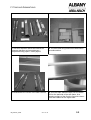
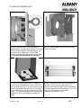
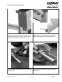
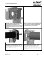
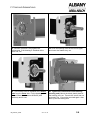
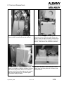
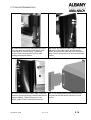
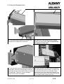
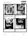
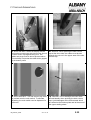
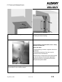
FITTING AND DISMANTLING
5
Assembly and Dismantling RR Clean
Risk of injury
Improper handling of the packaged door can lead to injury.
Place palette on an even surface.
Do not remove palette before starting assembly.
5.1
Inspection of the delivery
The door is largely pre-assembled on delivery. The side frames, top roll cover,
motor cover (if supplied), fixing materials and control system are secured to a
transport frame (wooden palette).
5.2
•
Check door for damage incurred during transit
•
Check that the delivery is complete by comparing it with the order
documentation.
Preparation for assembly
DANGER
Risk of injury
Incorrect assembly of the door can lead to injury.
Isopanel walls, chequer bricks and light partition walls must be checked for
their suitability for assembly.
The door may only be assembled by trained staff.
The door may only be assembled by the manufacturer or an installation firm
approved by the manufacturer.
Make the following preparations before assembling the door:
•
Inspect the installation site for the necessary fixing points and assembly
requirements: assemble a substructure or other suitable fixing options if
necessary. Screw the upper fixing points to a steel substructure or concrete
element. The fixing plan can be found in the user manual.
•
Measure clearance dimensions (width and height) of the door opening and
compare with the order.
•
Cordon off the installation site against people and vehicle movements.
•
Remove shrink-wrap from the packaged door.
IM_RRClean_EN04
2011-10-19
5.1
FITTING AND DISMANTLING
1. The door shipment should be checked for
transport damages and completeness –
compare delivery papers / order papers.
2. The drive and fixing material are delivered in
a cardboard box.
3. Disassemble the covers of the side columns.
4. Glue the foam adhesive tape over the whole
DH on the wall side of the side frame. At a
slanting surface of the floor the first side column
must be installed on the higher side.
IM_RRClean_EN04
2011-10-19
5.2
FITTING AND DISMANTLING
5. Set up the first side column and secure it
against tilting, e.g. with screw clamps. First side
column must be exactly vertically aligned, e.g.
by a water level. Make sure, that the side
column is sealed against the wall (arrow). This
is important for the tightness of the door.
6. Fix the head plate at the wall with 3 screws
(are not included).
7. The bottom plate is fixed with 2 screws (are
not included). Alternatively the side column can
be fixed at the wall with 1 screw (ensure to avoid
collision with cable chain when door is closed).
Hole for the screw is not yet drilled into the side
column. The element marked by an arrow is only
available for doors with leading photoelectric
barrier.
8. Set up the second side column by means of
the cable conduit (=exact light width). Preexamine the length of cable conduit. Difference
in height between side columns max. 3 mm. The
lower side must be lined, if necessary.
Tolerance B-measure ± 3mm.
IM_RRClean_EN04
2011-10-19
5.3
FITTING AND DISMANTLING
9. Screw the cable conduit onto the destined
positions at the side columns. The seal must
rest against the wall. The seal is glued on the
side with the right-angled axle (see fig. 10).
10. Detailed views of cable conduit: the seal is
marked by an arrow. Use flange head screws
M6x12 and hexagon socket screws M5x10.
11. Dismantle the feather key on the drive side
of the top roll.
12. Dismantle the bearing on the drive side of
the top roll.
IM_RRClean_EN04
2011-10-19
5.4
FITTING AND DISMANTLING
13. At the bearing side the black plastic plate
which is fixed at the head plate is to be
dismantled. Thereto remove the circumferential
hollow seal, the marked screw and the marked
screw nut.
14. Lift-up the top roll (with curtain) with the help
of crane or forklift. If the door is small, this can
be done manually by hand (2 persons).
15. Push the top roll through the head plate at
the drive end (long shaft extension). If the door
panel rests against the head plate, swivel the
top roll in direction to the wall.
16. Screw the bearing of the top roll onto the
bearing end (short shaft extension). Use 2
slotted fillister head screws M10x20 (with
washers). The bearing must be installed at the
bearing end (short shaft end) from the inner
side.
IM_RRClean_EN04
2011-10-19
5.5
FITTING AND DISMANTLING
17. Screw 2 nuts M10. Only tighten the
nuts/screws, if the bearing is installed at the
drive end, too.
18. Push the bearing onto the drive end again
and insert the feather key, too.
19. The bearing must be installed at the motor
side from the outer side. Fix the bearing with 2
slotted fillister head screws M10x20 (with
washers) and 2 nuts.
20. Tighten the nuts/screws of the bearing
(bearing end). Mount the black plastic plate at
the bearing end, too. Thereto the screw and nut
pictured in fig. 13 must be mounted again. Also
stick up the circulating seal.
IM_RRClean_EN04
2011-10-19
5.6
FITTING AND DISMANTLING
21. Put on the drive; pay attention to the feather
key connection.
22. For screwing the torque arm use washers
and self-securing nuts M8. The screws in the
head plate are already pre-mounted.
23. Insert the wall plate for the motor cover with
2 flange head screws onto the 6 mm thick sheet
at the head plate.
24. Only if the cables to the door are laid
through the bottom of the motor cover. Use
the counter sunk screws M5x20 and nuts to fix
the cover plate (arrow).
IM_RRClean_EN04
2011-10-19
5.7
FITTING AND DISMANTLING
25. Only if the cables to the door are laid
through the bottom of the motor cover. The
laying of the cables and the fixing of the cable
feed through is shown in the figures 74 to 78. Do
not fix the cable feed through, now; go on
with figure 28.
26. Only if the cables to the door are laid
through the wall plate of the motor cover.
(Shown without cable feed through). Use the
hexagon head screws M5x20 and nuts to fix the
cover plate. The counter sunk screws M5x20 are
marked with an arrow. Lay the cables through
the cable feed through as shown in the
figures 75 to 77, go on with figure 75.
27. Only if the cables to the door are laid
through the wall plate of the motor cover.
Use the counter sunk screws M5x20 and nuts to
fix the cable feed through.
28. Fix the wall plate for the motor cover at the
wall with 4 screws (are not included). Between
the side part and the wall plate a gap of approx.
4mm must remain (see arrow).
IM_RRClean_EN04
2011-10-19
5.8
FITTING AND DISMANTLING
29. Detailed view gap (approx. 4mm) between
side part and wall plate for the motor cover
(arrow).
30. Run the cable of the photoelectric barrier(s)
and, if provided, the cables of the integrated
impulse generator through the cable conduit
from the bearing end to the drive end.
31. Fix the cables being run through the conduit
at the black plastic plate at the drive end by
means of a cable strap.
32. Doors with MCC: (only assembling aid).
Screw the control onto a holding plate at the
side column at the drive end. The holding plate
is already screwed at the MCC. Screwing height
above 2000 mm.
IM_RRClean_EN04
2011-10-19
5.9
FITTING AND DISMANTLING
33. Doors with MCC: (only assembling aid).
Picture of MCC screwed at the side column.
34. Doors with MCC and UPS: plug on the
connector for the LED in the side column, as
shown; drive end right is pictured. At drive end
left the connector is to be plugged on from the
bottom. Take care of the connector’s position.
35. Doors with MCC: Screw the main control
switch on a height of 1250mm (900mm) into the
side column (drive end). Notice: the 4 screws
(arrows), which fix the steel plate at the holding
plate, are secured with nuts. The steel plate
must remain easily movable.
36. Doors with MCC: Screw the main control
switch onto the steel plate with 2 fillister head
screws M4x10.
IM_RRClean_EN04
2011-10-19
5.10
FITTING AND DISMANTLING
37. Doors with MCC and UPS: Out of the main
switch control a second cable is lead through
from above.
38. Doors with MCC: The cable led from the
bottom up of the main switch control, must run
upwards in a little radius behind the holding
plate of the main switch (do not bend).
39. Doors with MCC: Fix the cable which is led
down from the main switch at the holding plate
by means of a cable strap.
40. Doors with MCC: Fix the cable which is led
down from the main switch with a second cable
strap in the upper area of the holding plate. The
cable which is led out of main switch from above
is to be run into the cable conduit on short way.
IM_RRClean_EN04
2011-10-19
5.11
FITTING AND DISMANTLING
41. Release the safety of door leaf.
42. Lower the door blade to working height.
For lowering the door leaf, release the brake of
the drive unit. Turn the door blade by hand.
Actuating of the brake see fig. 43.
43. The brake which is flanged at the gear unit is
actuated by lifting and counter boring of the
black bracket.
IM_RRClean_EN04
2011-10-19
44. Loosen the screws before pushing the end
profile onto the curtain.
Do not remove the screws!!
5.12
FITTING AND DISMANTLING
Door
installed
inside the
excess
pressure
area
Door
installed
outside the
excess
pressure
area
Überdruck
excess
pressure
excess
Überdruck
pressure
45. Attention: the rubber lip of the bottom profile
is curved. The rubber lip must be pressed
towards the bottom via the excess pressure.
If necessary the bottom lip has to be turned.
46. Attention: the rubber lip of the bottom profile
is curved. The rubber lip must be pressed
towards the bottom via the excess pressure.
If necessary the bottom lip must be turned.
47. Push the bottom profile onto the bead of the
door blade.
48. Align the bottom profile to the middle
position in comparison to the door panel.
IM_RRClean_EN04
2011-10-19
5.13
FITTING AND DISMANTLING
49. Doors with prerunning photoelectric barrier:
Set in the slide and screw it with flange head
screws M6x12 (not too firmly). Tighten all
screws of the bottom profile. Picture: slide
leading photoelectric barrier.
50. Doors with electrical safety edge: Plug in the
M8 plugs of the cable chain and the bottom
beam. If inserted the cable carrier is behind the
slide. Picture shows the drive end left with cable
carrier.
51. Doors with electrical safety edge: Insert the
slide and screw with flange head screws M6x12
(tighten slightly). Tighten all screws of the
bottom profile. Picture shows drive end left.
52. The 2 holding plates of the seal sheet are
mounted at the seal sheet (similar to top roll
cover).
IM_RRClean_EN04
2011-10-19
5.14
FITTING AND DISMANTLING
53. The hollow seals, marked with arrows, are
important for the tightness of the door!
54. Make sure, that the seal sheet is sealed
against the wall (arrow). This is important for
the tightness of the door.
55. Push the seal sheet over the top roll and the
head plates. Screw the holding plate of the seal
sheet onto the 6mm thick sheet, which is fixed at
the head plate. Therefore, use the hexagon
socket screws (Allen key) M8x8.
56. Doors with MCC: the MCC will be screwed at
the seal sheet (like top roll casing). The MCC is to
be mounted at the drive end, the cable outlets
towards drive end. Doors with UPS (optional): the
MCC has cable outlets on both sides; the side with
a lot of cable outlets is at the drive end.
IM_RRClean_EN04
2011-10-19
5.15
FITTING AND DISMANTLING
57. Doors with MCC: The holding plates of MCC
are already fixed at the MCC. The holding plates
will be screwed at the seal sheet with each 2
flange head screws M6x12. The pictures show
the fixing positions.
58. UPS condition as delivered: the holding
plate is already screwed together with the UPS
housing. Do not dismantle the holding plate
before mounting at the seal sheet (like top roll
casing).
59. Screw the UPS to the seal sheet at the
bearing side. Put the flange head screw M6x12
through the UPS housing and the holding plate
and screw it into the seal sheet.
60. Picture of the screw which only connects the
UPS and the holding plate. The screw will not be
connected with the seal sheet.
IM_RRClean_EN04
2011-10-19
5.16
FITTING AND DISMANTLING
61. Doors with ACS50: The voltage divider must
be screwed to the seal sheet with 2 screws
M3x30 (drive side).
62. Flange head screws M6x12 have to be
screwed into the tap holes of the seal sheet,
which are not required.
63. Side column drive side: Remove the built in
rubber frame from the sheet frame. Strip one
half of the vertical hollow seal from the sheet
frame. For conducting the cables through the
sheet frame, a vertical stud of the sheet frame is
cut in.
64. Conduct the cables of the side column (drive
end) through the sheet frame. For this bend
open the sheet frame so far that the cables can
be conducted.
IM_RRClean_EN04
2011-10-19
5.17
FITTING AND DISMANTLING
65. Put the rubber frame over the cables,
arrange the cables so, that they fit through the
rubber bungs (thickness=12mm, belonging to
assembly bag). The rubber bungs are in the
assembly bag.
66. Bend back the sheet frame and fix the
hollow seal again. Push the rubber frame into
the sheet frame.
67. Push the rubber bungs onto the cable
assemblies.
68. Press the rubber bungs into the rubber
frame.
IM_RRClean_EN04
2011-10-19
5.18
FITTING AND DISMANTLING
MCC and UPS
drive side right
is pictured
UPS
Extension
MCC
MCC
Fuse
69. Side column drive side: picture of the
finished cable laying. Doors with MCC: Run the
cables towards control unit which is positioned
directly above the cable feed-through (remove
plugs from the cables). Doors with ACS50: Plug
the cables onto the voltage divider.
70. Connect the control units (MCC or ACS50),
photoelectric barriers, securities, impulse generators,
drive unit and (if included) UPS according to wiring
diagram. Attention: if the accumulator of the UPS is
charged, UPS and control unit are supplied with power.
The voltage feed of MCC can only be interrupted by
actuating the main switch. The voltage feed of UPS can
only be interrupted by actuating the fuse.
71. Doors with MCC: Run the cables from the
72. Doors with MCC: Mount the connection
socket for the electrical connector at the wall
plate for the motor cover with 2 fillister head
screws M4x8.
control to drive unit, net and (optional) impulse
generator through the clearing in the 1,5mm
thick sheet. Doors with ACS50: Run the cables
from the voltage divider through the clearing in
the 1,5mm thick sheet. Use edge protectors!
IM_RRClean_EN04
2011-10-19
5.19
FITTING AND DISMANTLING
73. Doors with MCC: Run the cables which are
too long on the MCC, UPS and the seal sheet
(similar to top roll cover). If the cables are laid
through the wall plate of the motor cover: go
on with figure 79.
74. Doors with MCC: Lay power line and
(optional) cables for extern impulse generators
through the wall plate motor cover. Doors with
ACS50: The cables which must be laid from the
control into the door, should be run through the
wall plate motor cover (circuit to drive, to voltage
divider).
75. Unscrew the cable feed through. Push the
suitable rubber bungs (thickness=19 mm) over
the cables.
76. Push the cable via the feedthrough as far as
necessary. Screw together the cable
feedthrough.
IM_RRClean_EN04
2011-10-19
5.20
FITTING AND DISMANTLING
77. Picture above: Cut in the seal at a short side. 78. Push the hexagon head screws M5x20 from
Move the seal over the cables. Picture below:
the bottom up through the wall plate of the motor
Affix the seal onto the wall plate for the motor
cover; fix them above with nuts.
cover. If the cables to the door are laid
through the wall plate of the motor cover: go
on with figure 27.
79. Integrated, non-touch impulse transmitter
(optional). Connect the impulse transmitter by
wiring diagram. Fix the impulse transmitter with
double-faced adhesive tape (the tape is in the
box already).
IM_RRClean_EN04
2011-10-19
80. Integrated, non-touch impulse transmitter
(optional). Adjust the distance for the activity of
the impulse generator by means of the
regulation screw (arrow). This adjustment can
only be made if the side column cap is open.
5.21
FITTING AND DISMANTLING
81. Doors with MCC: Attach the display with the
plug before mounting the side column cap. Secure
the side column cap against tilting over. The
cables and plugs must be laid as pictured above.
This definitely avoids that the cable will be gripped
by the bottom profile.
82. Attention: When pushing the side column
cap at the drive side, the cables must be laid
through the cut-out in the upper area of the side
column cap.
83. Doors with MCC: The side column cap must
be pushed onto the main switch. To alleviate
threading, the main switch can be displaced for
a few mm.
84. Attention: Do not damage the foam seals
affixed laterally when pushing the side column
cap. Avoid damages at the hollow seals which
are affixed at the bottom plate and at the area of
the upper sealing sheet.
IM_RRClean_EN04
2011-10-19
5.22
FITTING AND DISMANTLING
85. Doors with MCC: Pushed side column cap in
the area of the main switch. The arrow points to
the LED for the UPS (optional). Stick the label
for the main switch on the side frame.
86. The side column caps are screwed to the
side columns via boreholes which are made as
elongated holes. Screw in all flange head
screws M6x12 and tighten them if all the screws
are inserted.
87. The clearance between side column and side
88. For adjusting the final position(s), the cover
plate at the drive must be removed.
column cap must be 4-5mm. If the clearance is
smaller, the bottom profile gets caught. If the
clearance is bigger, the leakage of the door
increases. Use a hexagon socket screw key (Allen
key) for facilitating the inspection. If necessary,
correct the clearance.
IM_RRClean_EN04
2011-10-19
5.23
FITTING AND DISMANTLING
Screw A
Screw B
S1 Emerg.UP
S2 Emerg. DOWN
S3 UP
S4
S5
S6
DOWN
CUTOFF STAT. PHOTOCELL
ADDITIONAL
89. Connect the electric system.
Adjust the cam limit switch under considering
the end position.
S4 and S5 are only needed for
ACS 50. Failures in setting
may cause damages!
90. After rough setting tighten screw A and do
not unscrew again as possible (secure by
lacquer).
The fine adjustment of the end positions are
made via screw B.
92. Advice for setting the lower end position:
If there are pressure differences the door
shall avoid too large volume flow rates.
30 – 50 mm
Do not set the lower stop position too high. The
lip seal of the bottom profile must be in contact
with the floor even in case of maximum pressure
differences.
Do not set the lower stop position too low. The
weight of the bottom profile should level the door
panel if the door is closed.
Set end position (S4)!
Only at ACS 50
91. Adjust the cam limit switch S4 so that it is
activated at an opening height of 30 – 50 mm.
Doors with MCC: the lower end position and the
shut-off point of the photocell are set via control
unit. Mount the covering cap at the drive unit
again.
IM_RRClean_EN04
2011-10-19
5.24
FITTING AND DISMANTLING
93. Set the position of the beam. If the door is
assembled inside of the excess pressure area
(fig. 46), adjust the beam so that the head plate
has a large distance to the door blade (as big as
possible).
94. Set the position of the beam. If the door is
mounted outside of the excess pressure area
(fig. 45), adjust the beam so that the door blade
fits closely in case the intended excess pressure
is reached in the room and the door is closed
(middle of elongated hole).
95. Connect the equipotential bonding. Use a
hexagon head screw M8x16 with washers
(Arrow).
96. Push the motor cover onto the drive unit and
the wall plate for the motor cover. Tighten the
motor cover with 3 flange head screws M6x12.
IM_RRClean_EN04
2011-10-19
5.25
FITTING AND DISMANTLING
97. Plug in the rubber plug in the motor cover.
98. Use the cage nuts marked by arrows for
screwing the top roll casing.
The assembly is finished after test of safety
devices and test run.
Clean the door.
The dismantling is made in opposite direction to
installation.
The packing material of the door may be
returned to the manufacturer.
Defective door components should be disposed
at site according environmental regulations.
Defective electronic components should be
disposed as special waste.
99. Fix the top roll casing with 4 flange head
screws M6x12 at the holding angles.
IM_RRClean_EN04
2011-10-19
5.26