1
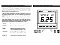
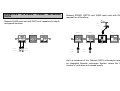
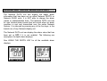
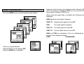
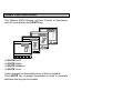
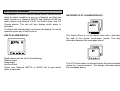
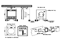
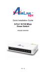
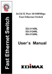
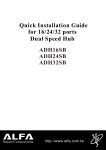
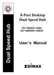
CONTENTS
NETWORK ALARMS............................................................. 11
CONTENTS..............................................................................1
GENERAL INTRODUCTION TO B&G NETWORK ................2
INTRODUCTION TO NETWORK DATA .................................3
EXAMPLE SYSTEMS USING NETWORK DATA...................4
ALARMS AND THE NETWORK DATA UNIT .........................5
FAULT AND ERROR MESSAGES ....................................... 12
INSTALLATION ................................................................ 13,14
SITING THE UNIT ............................................................... 13
MOUNTING THE UNIT........................................................ 13
SPECIFICATION ................................................................... 15
CONDITIONS OF WARRANTY
USING THE SPEED KEY ........................................................6
USING THE DEPTH KEY ........................................................7
USING THE WIND KEY...........................................................8
USING THE OPTIONS KEY ....................................................9
USING THE LIGHTS KEY .....................................................10
1
GENERAL INTRODUCTION TO B&G NETWORK
The B&G Network range of instruments is designed to be
used as individual units or connected together to form an
integrated navigational system. A single network cable is
used to carry data and power between units. The latest
technology and screened cables throughout the Network
System ensure the ultimate protection from interference
between units and other systems. All Network instruments
can be linked to Network PILOT, Network CHART, Network
GPS or Network LORAN receivers or via NMEA 0183 (v1.5)
to other navigational equipment.
INSTRUMENTS
NAVIGATIONAL AIDS
Network SPEED
Network DEPTH
Network QUAD
Network WIND
Network TACK
Network DATA
Network GPS
Network LORAN
Network NAV
Network CHART
AUTOPILOTS
COMMUNICATIONS
Network PILOT
Network VHF
2
INTRODUCTION TO NETWORK DATA
NETWORK DATA DISPLAY UNIT
The Network DATA unit is a repeater of available networked
information supplied from other Network Instruments via the
system network. The information is presented on a large
back-lit Liquid Crystal Display (LCD).
It has no sensor interfaces as all data is passed to the unit via
the system network cables. The unit is capable of transmitting
NMEA 0183 v1.5 data via the network cables. The Network
DATA unit has its' own internal buzzer that sounds when an
alarm condition is met and received via the system network
from other Network units. The row of five keys are used for
selecting the displayed information when the appropriate unit
and its sensor is connected to the Network DATA unit.
• SPEED
Current, maximum and average speed
• DEPTH
Water depth and depth alarms
• WIND
Apparent wind speed and angle,
True wind speed and angle, VMG.
• OPTIONS
Heading, DR distance, DR course,
Temperature, Timers, Battery Volts.
• LIGHTS
Three levels of illumination and off.
3
EXAMPLES
DATA
SYSTEMS
USING
NETWORK
Network SPEED, DEPTH and WIND main units with DATA
repeater for all functions.
Network QUAD main unit with DATA unit repeaters for depth
and speed functions.
Wind
Sensor
QUAD
DATA
SPEED
DATA
DEPTH
DATA
SPEED
DEPTH
WIND
Depth
Speed
Sensor
Sensor
Speed
Depth
Sensor
Sensor
Up to a maximum of four Network DATA units maybe used in
an integrated Network Instrument System, where the total
number of units does not exceed twenty.
4
ALARMS AND THE NETWORK DATA UNIT
The Network DATA unit can display the depth alarm
information that has been set on either Network DEPTH or
Network QUAD units. It is NOT able to change the alarm
values or enable/disable them. The Network DATA unit has
its' own internal alarm buzzer that will sound when an alarm
condition is met and transmitted over the entire Network
System. It is silenced by pressing any of the five keys, in the
lowest row, of any Network display unit.
The Network DATA unit can display the alarm value that has
been set or OFF if it is not enabled. The following are
examples of a depth alarm displays.
See USING THE DEPTH KEY for all the available alarm
displays.
DEPTH
DEPTH
5
USING THE SPEED KEY
Press the SPEED key to cycle through the speed options.
The speed information is only displayed when the Network
DATA unit is connected to a Network QUAD or Network
SPEED unit. The units in which the speed and log information
is display is set on the main display unit.
When speed data is available the following can be displayed:
SPEED
If there is no speed data the
Network DATA unit will display OFF
when the SPEED key is pressed.
• SPEED KT
Boat speed in Knots KT or MPH MH.
• MX SP KT
Maximum boat speed since the last reset
of the trip log.
• AV SP KT
Average boat speed since the last reset
of the trip log.
• TRIP NM
The trip log value in Nautical Miles NM or
Statute Miles M.
• LOG NM
The stored log in Nautical Miles NM or
Statute Miles M.
SPEED
6
USING THE DEPTH KEY
Press the DEPTH key to cycle through the depth options.
The depth information is only displayed when the Network
DATA unit is connected to a Network QUAD or Network
DEPTH unit. The depth units and the alarm values are set on
the main unit.
When depth data is available the following can be displayed:
• DEPTH M
Water depth in metres M, feet FT,
fathoms FA.
• DEP A M
Deep water alarm. The display will show
the value or OFF.
• SHA A M
Shallow water alarm. The display will
show the value or OFF.
• ANC A M
Anchor watch alarm. The display will
show the values alternatively or OFF.
DEPTH
If there is no depth data the
Network DATA unit will display OFF
when the DEPTH key is pressed.
DEPTH
7
USING THE WIND KEY
Press the WIND key to cycle through the wind options.
Apparent wind functions are displayed when Network DATA
unit is connected to a Network WIND unit, true wind and VMG
also require a Network SPEED unit.
When wind and speed data is available the following can be
displayed:
AWA Apparent wind angle in degrees.
AWS KT
Apparent wind speed in knots KT.
TWA
True wind angle in degrees.
TWS KT
True wind speed in knots KT.
VMG KT
Velocity Made Good in knots KT.
AWA and TWA are indicated to Port or to Starboard by the
position of the displayed legend.
PORT
STARBOARD
WIND
If there is no wind data the
Network DATA unit will display OFF
when the WIND key is pressed.
WIND
WIND
WIND
8
USING THE OPTIONS KEY
Press the OPTIONS key to cycle through the options.
The information is only displayed when the Network DATA
unit is connected to Network PILOT and Network SPEED or
Network QUAD units.
When connected to the appropriate units the following can be
displayed:
HEADING Compass heading supplied from Network
PILOT's internal fluxgate compass.
DR D NM Dead Reckoned Distance in NM or M.
OPTIONS
If there is no data available the
Network DATA unit will display OFF
when the OPTIONS key is pressed.
OPTIONS
DR C 0M
Dead Reckoned Course in degrees
Magnetic M.
TEMP 0C
Sea water temperature in degrees
Celsius C or Fahrenheit F.
TIMER
Timer, Hours and Minutes in large digits,
Seconds in small digits.
LAP
Lap timer, reset on main unit.
BATTERY Battery volts.
9
USING THE LIGHTS KEY
The Network DATA Display unit has 3 levels of illumination
and off, controlled by the LIGHTS key.
LIGHTS
LIGHTS
LIGHTS
LIGHTS
• LIGHTS 0 OFF
• LIGHTS 3 High
• LIGHTS 2 Medium
• LIGHTS 1 Low
It also changes the illumination level of the key legends.
The LIGHTS key is always illuminated so even in complete
darkness the key can be located.
10
NETWORK ALARMS
The Network DATA unit has an internal buzzer that will sound
when an alarm condition is met on a Network unit that has
alarm functions ie. Network DEPTH and Network QUAD for
depth alarms and Network PILOT for Watch Alarm and Off
Course alarms. The unit will also display which alarm is
activated.
NETWORK PILOT ALARM DISPLAYS
To silence the internal alarm and return the display to normal
operation press any of the five keys.
DEPTH ALARM DISPLAY
Depth alarms can be set for the following:
Shallow water
Deep water
Anchor Watch
Check your Network DEPTH or QUAD unit to see which
alarm is activated.
The Watch Alarm is a count-down timer with is activated at
the end of the preset count-down period. The display
alternates between the messages above.
The Off Course alarm is activated when the boat deviates off
course by a preset amount. The display alternates between
the messages above.
11
FAULT AND ERROR MESSAGES
UNIT INTERNAL ERRORS
NETWORK PILOT FAULT DISPLAY
If Network PILOT should have a fault the autopilot computer
unit will send a message to all other Network Display Units.
The Network DATA unit will alternately display the follow
message, the actual fault will have to read from the Network
PILOT Display unit.
In the unlikely event that your Network DATA unit should
develop an internal error, the unit will sound it's alarm
continuously and the display will show an error number.
Pressing the keys will not silence this alarm.
In some cases the fault can be cleared by switching off the
instruments at the supply, waiting a few moments and then
switching on again. If this does not clear the fault the error
number should be recorded.
Switch off the supply and disconnect the faulty unit. Return it
with the error number to your dealer for servicing.
12
INSTALLATION
MOUNTING THE UNIT
The display heads are supplied with a clip-in mounting
bracket which allows for easy installation, access from behind
is not necessary to secure the unit in place. However to
prevent theft and permanently fix the unit in position, locking
studs and thumb nuts are supplied.
Use the cutting template supplied to mark the centres of the
holes for the self-tapping screw, the fixing stud holes and the
mounting bracket.
SITING THE UNIT
All Network Instruments are designed for mounting on or
below deck. A mounting position should be selected where
they are:
• Easy to read by the helmsman
• On a smooth and flat surface
• At least 100mm (4") from a compass
• Accessible from behind for fitting locking studs if
required.
• The template allows 4mm (5/32") between adjacent units for
the suncover, increase this distance if required to maximum of
60mm (2 3/8") between units or 180mm (3 1/8") between
centres. For greater distances between units extension cables
are available.
• Use a 70mm (2 3/4") diameter hole-cutter for the mounting
bracket hole.
• Use a 2.9mm for the self-tapping screw holes.
• Use a 5mm (3/32") drill for the locking stud holes.
• Secure the mounting bracket to the bulkhead with the
self-tapping screws supplied
• Fit the rubber sealing gasket around the mounting bracket.
• Screw the locking studs into the back of the display head (if
required).
• Carefully pass the cable tails through the mounting bracket
hole, connect the cables to the main units.
• Clip the display head into the mounting bracket.
• Secure the instrument with the thumb nuts supplied.
13
INSTALLATION
14
SPECIFICATION
PHYSICAL PARAMETERS
Constuction
Window
Display
Dimensions
Weight
High impact ABS plastic
Acrylic
Back-lit Liquid Crystal Display:
Large Digits: 28.6mm 1.12"
Small Digits: 11.5mm 0.45"
110 x 110 x 25.4mm 4 x 4 x 1"
Requires 65mm 2.6" depth behind
bulkhead for display barrel
0.3 kg 0.66lbs
ENVIRONMENTAL
Operating Temp -10 to +550C @ 93%RH
+14 to +1310F @ 93%RH
Storage Temp -25 to +700C @ 95%RH
-13 to +1580F @ 93%RH
Humidity
Up to 95%RH
Sealing
Fully sealed front, suitable for bulkhead
cockpit mounting. Vented barrel to prevent
condensation.
ELECTRICAL
Power Supply
Operating Current
Protection
12V DC nominal (10 to 16V)
40mA typical, 100mA illuminated
Connect via external fuse or
circuit breaker.
CABLES AND CONNECTIONS
Connection to adjacent units is via cable tails fitted with either
a plug or a socket. Extension cables are available from your
dealer. The cable tails carry power and NMEA data between
units.
ALARM
Internal audible alarm
NMEA OUTPUT SENTENCES
$IIHDM
$IIVHW
$IIDBT
$IIVWR
$IIMTW
Heading
Speed and Heading
Depth
Apparent wind angle and speed
Sea temperature
15